Huawei OptiX OSN 3500 Hardware Description ISSUE 1.1 - part 8
Cross-Connect and Timing Unit
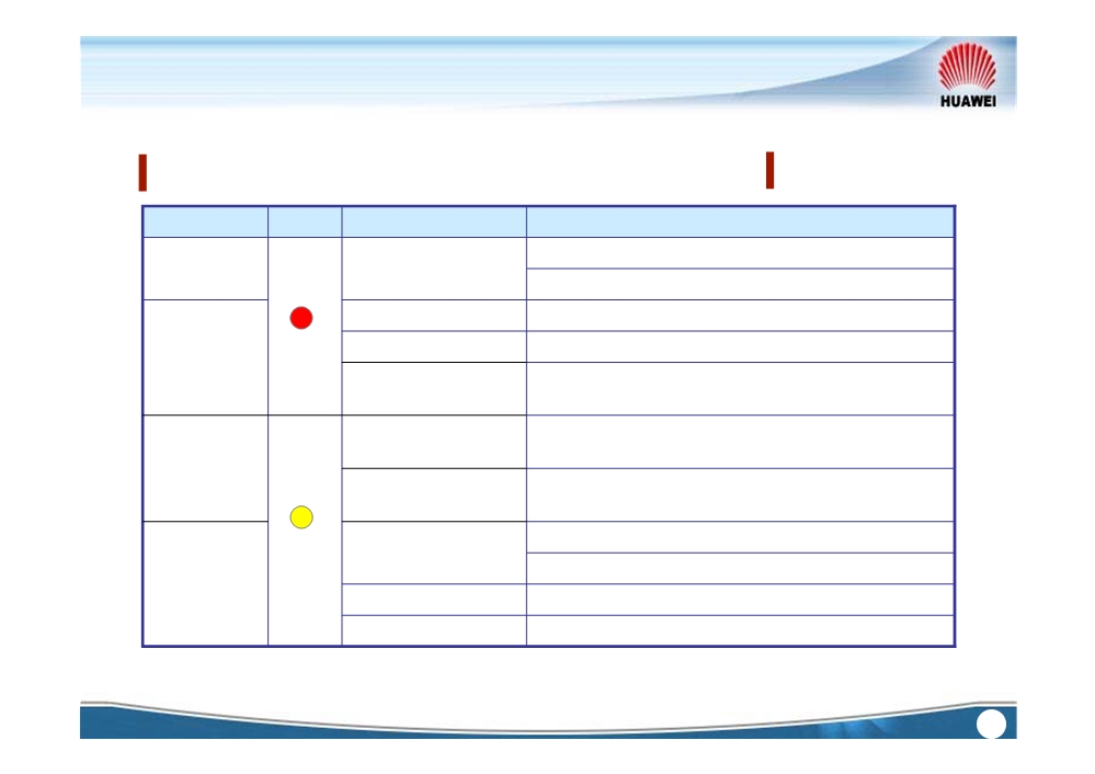
The common alarms of Cross-Connect and Timing unit
Alarm level
Color
Alarm name
Alarm reason
Chip of the cross-connect board is damaged
Critical
BUS_ERR
Damaged backplane bus
APS_INDI
MSP switching happens
TEMP_OVER
Ambient temperature is too high.
Major
Ejector lever on the front panel is rotated to the
W_OFFLINE
open position.
Physical interface signal of the external clock
EXT_SYNC_LOS
source is lost.
Minor
CLOCK_ENTER_N
Clock working mode changes from locked into
O_TRACE_MODE
holdover or free-run.
Multiplex section protection switching fails.
APS_FAIL
MS node information is lost or set incorrectly
Warning
SWITCH_DISABLE
Board switching is disabled
OTH_BD_STATUS
Another board pulled out or plugged in
Internal Use
78
1. SDH unit
2. PDH unit
3. Ethernet unit
4. ATM unit
5. MST unit
6. WDM unit
7. Cross connection and timing unit
8. SCC unit
9. Auxiliary unit
Internal Use
79
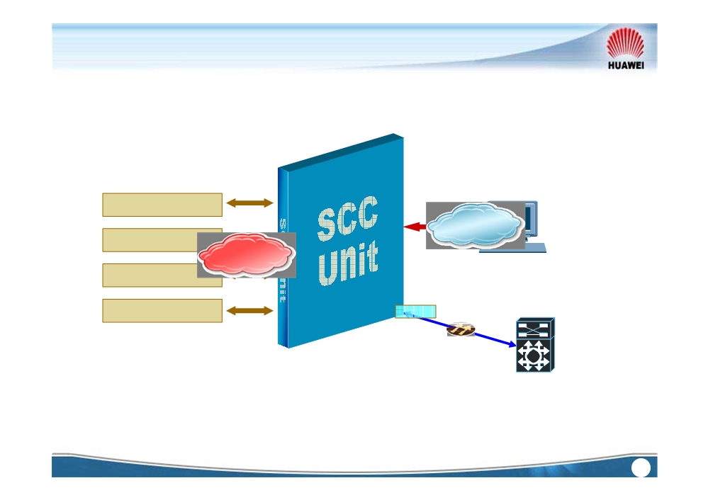
System Control & Communication Unit
SDH unit
Commands
PDH unit
Alarm and
performance
NMS
Ethernet unit
Cross-connect unit
DCC
Other NE
Internal Use
80
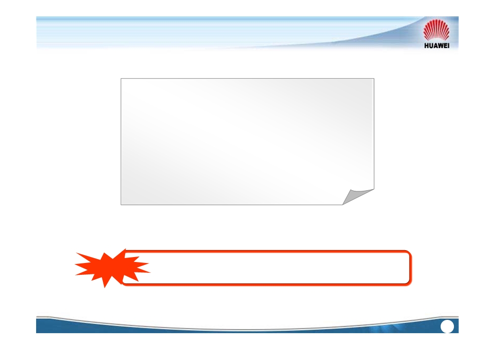
System Control & Communication Unit
Setting NE ID by software
1+1 hot backup
Extended ECC
Controls cabinet indicators and fans
16 Housekeeping alarm inputs and 4 alarm
outputs
GSCC supports ASON, but SCC does not.
Note
Internal Use
81
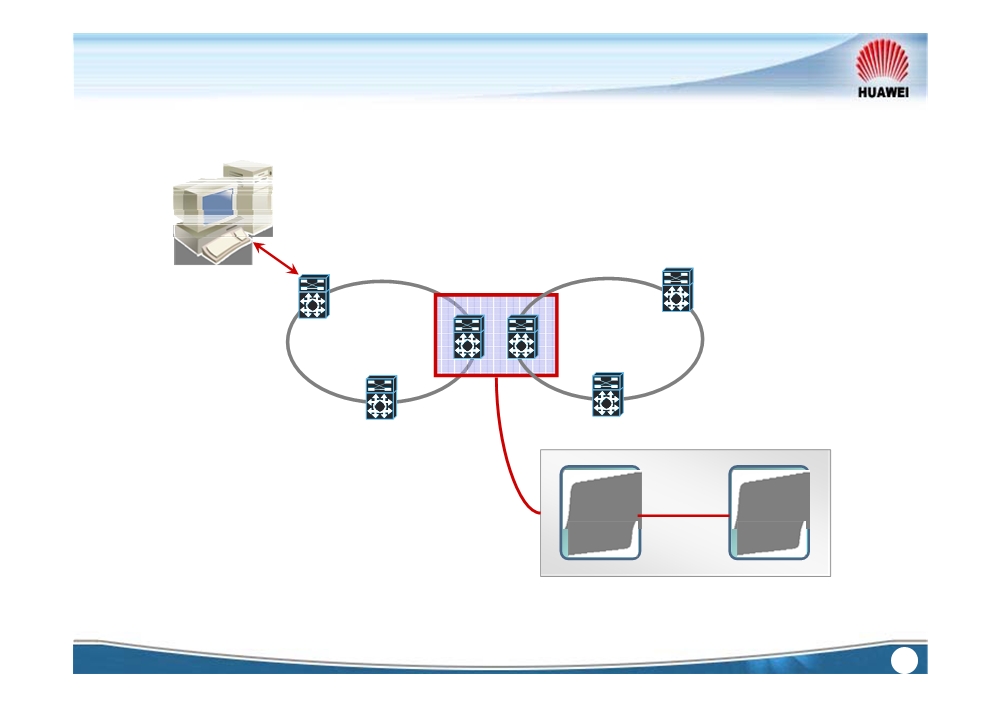
System Control & Communication Unit
NMS
Ring A
Ring B
L< 50m
Ethernet
Ethernet
port
port
Internal Use
82
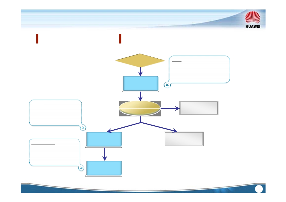
System Control & Communication Unit
Four databases on the SCC
MDB
Issued data
Automatically saves the current
data in dynamic RAM.
If power fails, the data in MDB
will be lost.
MDB
DRDB
NE in installing
Fail
Automatically saves the
verify
status
successfully verified data.
If power fails, the data in
Success
DRDB will be lost.
NE & Boards in
DRDB
running status
FDB0, FDB1
Manually or periodically
saves the data. Enduringly
Save manually or
saves data and does not
periodically every 30 mins
need battery.
FDB0
FDB1
Internal Use
83
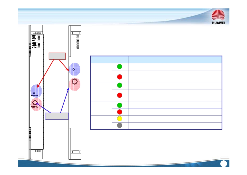
System Control & Communication Unit
GSCC
STAT
ACT
PROG
SRV
PWRA
PWRB
PWRC
ALMC
Reset
Indicator
Color
Description
The -48 V power supply A is normal.
RESET
PWRA
The -48 V power supply A is faulty (lost or
failed).
ALM CUT
The -48 V power supply B is normal.
PWRB
The -48 V power supply B is faulty (lost or
failed).
The 3.3 V protection power is normal.
PWRC
The 3.3 V protection power is lost.
Alarm cut
Currently in permanent alarm cut-off status.
ALMC
Give audible warning upon alarm.
GSCC
Internal Use
84
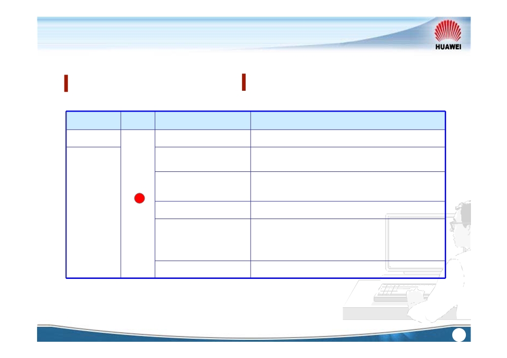
System Control & Communication Unit
The common alarms of SCC unit
Alarm level
Color
Alarm name
Alarm reason
Critical
NESTATE_INSTALL
NE is in the installing state.
Software in the master and slave SCC are
MSSW_DIFFERENT
mismatched
Inserted board and the configured board are
WRG_BD_TYPE
mismatched.
NESF_LOST
Host software is lost.
Major
Faulty power resource, e.g. the
3.3V power
POWER_ABNORMAL
module of the SCC or AUX, and the 3.3V backup
power module, and 2 channels of -
48V
POWER_FAIL
Too low battery voltage on the SCC
Internal Use
85
1. SDH unit
2. PDH unit
3. Ethernet unit
4. ATM unit
5. MST unit
6. WDM unit
7. Cross connection and timing unit
8. SCC unit
9. Auxiliary unit
Internal Use
86
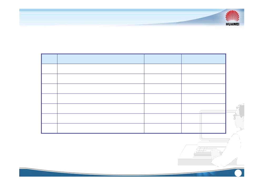
Auxiliary Unit
No.
Board
Board name
Available slots
1
Auxiliary Interface Board
AUX
37
2
Power Interface Board
PIU
27, 28
3
Booster Amplifier Board
BA2
1 ~ 8, 11 ~ 17
4
Pre-amplifier Board
BPA
1 ~ 8, 11 ~ 17
5
Case-based Optical Amplifier
COA
External
6
Dispersion Compensation Board
DCU
1 ~ 8,
11 ~ 17
7
Fan unit
FANA
Null
Internal Use
87
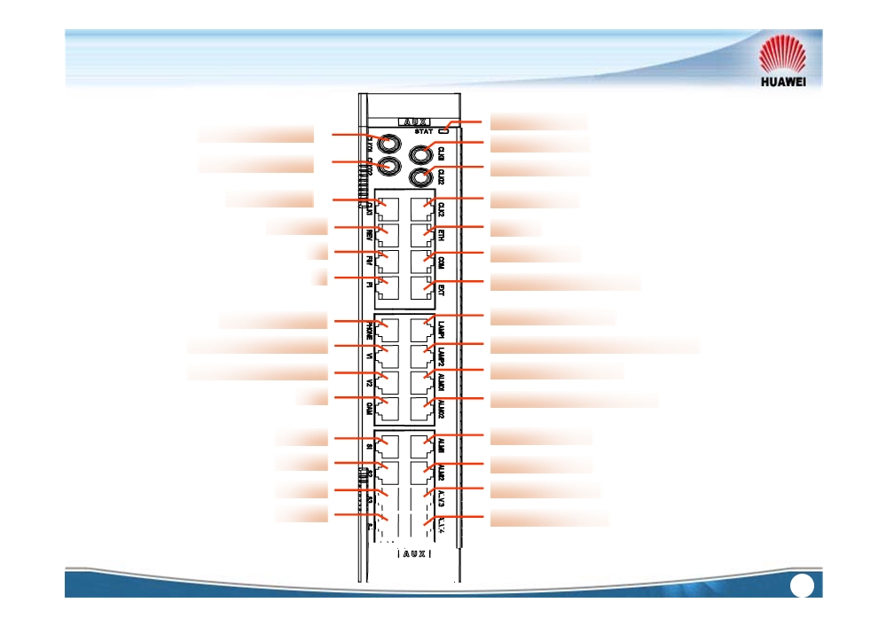
Auxiliary Interface Board -AUX
Indicator STAT
75Ω clock OUT 1
75 Ω clock IN 1
75 Ω clock OUT 2
75 Ω clock IN 2
120 Ω clock 1
120 Ω clock 2
Reserved
NM port
F&f
COM test port
F1
Extended sub-rack port
4 cabinet indicators
Orderwire phone
SDH NNI telephone 1
cabinet indicators concatenation
SDH NNI telephone 2
Alarm concatenation
OAM
Boolean alarm output 1~4
Series 1
Alarm input 1~4
Series 2
Alarm input 5~8
Series 3
Alarm input 9~12
Series 4
Alarm input 13~16
Internal Use
88