TM 10-8400-203-23&P. Manual - part 18
 

  Index      Manuals     TM 10-8400-203-23&P. Repair Manual 2010 year


Search            copyright infringement  


Content   ..  16  17  18  19   ..


TM 10-8400-203-23&P. Manual - part 18


 TM 

10-8400-203-23&P 

0019 

REPAIR - CONTINUED 

0019-7 

Replacing the Upper Cable  
 
1.  Remove the foam fillers and earphone from the left ear-cup.  

2.  Unplug all mini connectors leading from the upper cable. All cables are colored coordinated.  

3.  From the outside of the ear-cup, unscrew the two screws holding the cable into the ear-cup.  

4.  Replace in reverse order and seal around upper cable entry inside the ear-cup with silicone sealant. 

END OF TASK 
 
Replacing the Neck Cable Assembly  
 
1.  Noting the order of placement, remove all internal components from both ear-cups. 

2.  Cut the tie wrap off of both ends of the neck cable from within the ear-cups.  

3.  Cut off all mini connectors from both ends of the neck cable from within the ear-cups, and remove the 

neck cable. 

4.  Start inserting the new neck cable with the side showing the extra white conductor and black and 

orange conductors mounted on the same mini connector, into the left ear cup. The left ear cup is the 
side without the boom/microphone.  

5.  Fish the mini connectors into the ear-cup. Lubricate the rubber grommet with a soapy water solution 

and push and twist them into the ear cup holes. A small flathead screwdriver may be necessary to 
move the grommets.  

6.  After inserting the grommets into the ear cups, lubricate the inside of the grommets with soapy water 

solution and pull the cable into the grommet so that the neck cable is into the ear cup ¼ inch past the 
heat shrink tubing on the cable.  

7.  Tightly pull a nylon tie wrap around the cable assembly on this ¼ inch portion of the neck cable to 

prevent the cable from being pulled out of the ear cups. Plug in all the mini connectors. 


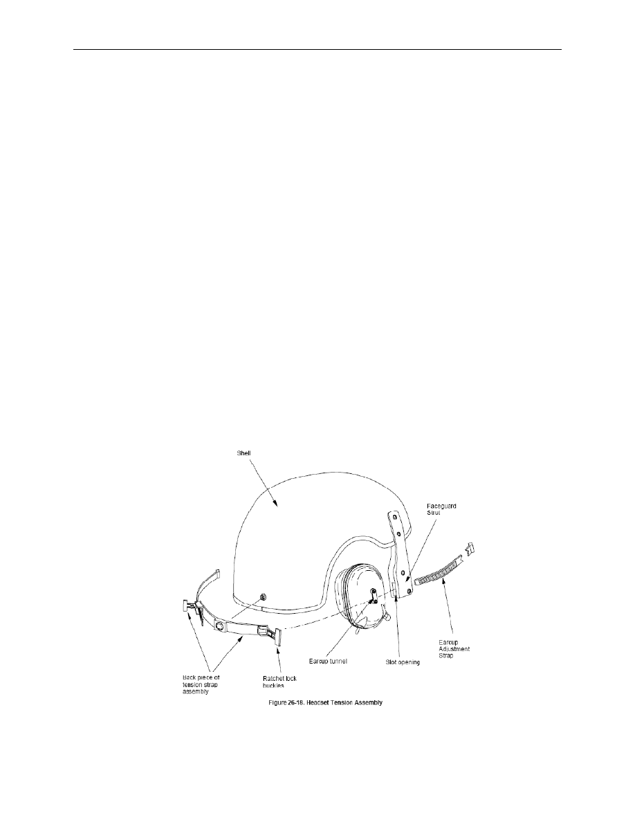
Figure 4. Headset Tension Assembly. 

END OF TASK 
 

 TM 

10-8400-203-23&P 

0019 

REPAIR - CONTINUED 

0019-8 

Replacing the Faceguard 
 
1.  Remove the faceguard by flipping it up pulling it away until it is disengaged. 

2.  To replace the faceguard, have it in the “up” position and engage the two metal swivel posts on the 

faceguard to the mating slots on the faceguard attachment strut.  

3.  Swivel faceguard down until it engages in detents of attachment strut. Grasp the right side of the 

faceguard and the right struts and rotate downward and back to lock the faceguard into position. A 
clicking noise indicates proper engagement. Repeat for left side. 


Figure 5. Faceguard Assembly. 

END OF TASK 
 
END OF WORK PACKAGE 

 TM 

10-8400-203-23&P 

0020 

0020-1 


FIELD MAINTENANCE 

CVC BODY ARMOR 

SERVICE, REPAIR 


INITIAL SETUP: 


Tools Personnel 

Required 


Knife, Hot Metal (WP 0046, Item 9) 

Non-MOS Specific (1) 

Ruler, Tab, Metal, 16-inch (WP 0046, Item 19) 


Sewing Machine, Bar Tack (WP 0046, Item 25) 

References 

Sewing Machine, Medium Duty (WP 0046, Item 
34) 

 
WP 0005 

Tape, Measuring (WP 0046, Item 39) 

WP 0007 

Shears (WP 0046, Item 36

WP 0045 

Stitch Removal Tool (WP 0046, Item 38) 

WP 0046 

 
INSPECT 
 
Perform PMCS inspection on all items IAW WP 0005 and determine serviceability IAW WP 0007. 

END OF TASK 

SERVICE 

Cleaning 
 

CAUTION 

Do not starch the carrier or the inserts. Do not bleach or dry clean the inserts. 


1.  Remove the ballistic inserts from the carrier and mate the hook-and-pile fasteners of the carrier for 

washing. Wash the carrier and the inserts separately. Wash the inserts as seldom as possible. 

2.  Hand wash the carrier and the inserts in warm to hot water and mild detergent. 

3.  Rinse thoroughly in clear warm water after laundering, Remove all soaps, alkalis and detergent or the 

vest will lose its ballistic or flame resistance. If the vest has accidentally been starched, its ballistic 
and flame resistance can be restored by rinsing thoroughly with warm water. If the inserts have been 
accidentally bleached, turn them in for replacement. Field Laundry Procedure: Wash the inserts and 
the carrier according to Laundry Wash Formula “l” of FM 10-280, Field Laundry, Bath and Clothing 
Exchange Operations.  

4.  Inspect the carrier and the inserts after washing to insure that there are no open seams, tears, or 

holes and that components operate satisfactorily. 

END OF TASK 

 TM 

10-8400-203-23&P 

0020 

0020-2 

REPAIR 
 
Carrier Replacement  
 
Due to the low cost of the complete carrier, it is not considered economical to repair badly torn, worn, or 
damaged carriers, including replacement of hook-and-pile fasteners, and elastic webbing. When a carrier 
has large holes or tears, is severely worn or soiled, has inoperative hook and- pile fasteners, or has badly 
abraded or otherwise damaged elastic webbing, replace the entire carrier. The carrier need not be 
replaced for tears or holes less than 1 inch long that can be repaired by hand darning, and for open 
seams that can be repaired by top-stitching. 
 
Carrier Repair 
 
Small holes or tears.
 With the ballistic inserts out of the carrier, the hole or tear in the carrier may be 
repaired by drawing the edges together and darning by hand.  
 
Open seams and broken stitches. When it is necessary to repair an open seam or broken stitching, use 
machines for all servicing except in emergency repair. Top stitch with Aramid thread conforming to MIL-T-
43636, size B, color olive drab S-1, E. A. 66022, size 50 for both needle and bobbin/looper. Use stitch 
type 301 of Federal Standard 751 and 8 to 10 stitches per inch. Adjust the thread tension so that there 
will be no loose stitching or excessively tight stitching resulting in puckering of the sewn material. 
Backstitch thread breaks and ends of stitching by 1/2 inch (1.27 cm) minimum. 
 
Ballistic Insert Replacement  
 
If any insert has any hole, tear, or cut in the ballistic cloth or if the insert has lumps or other damage, 
replace the insert. The insert need not be replaced for open seams or tears in the binding which can be 
repaired by topstitching, or even if the entire binding can be replaced. 
 
Ballistic Insert Repair 
 
When it is necessary to repair open seams, broken stitching, damaged binding or to completely replace 
the binding, use machines for all servicing except in emergency repair, and follow the instructions in No. 1 
and 2 below. Top-stitch with polyester thread conforming to Type 1, Class 1, Subclass A, size B, color 
natural of V-T-285 or nylon thread conforming to Type 1, Class A, size B, color natural of V-T-295. Adjust 
the thread tension so that there will be no loose stitching or excessively tight stitching resulting in 
puckering of the sewn material. Back-stitch thread breaks and ends of stitching by ½ inch (1.27 cm) 
minimum 
 
Open Seams or Broken Stitches
 
 
Fold binding under as originally folded and top-stitch with 8 to 10 stitches per inch. 
 
Replace Binding, Partially or Completely 
 
To replace a section of damaged binding, cut out the damaged area or completely remove the old binding 
and replace it with Atlantic Bias Products Style “Polyfrost” or equal, 45° bias binding tape, 1 7/8 inch (4.77 
cm) wide. Fold the binding as originally folded and top-stitch with 8 to 10 stitches per inch so that the 
finished binding covers 1/2 inch (1.27 cm) and stitching is 3/8 inch (0.925 cm) from the edge of the insert. 
Overlap ends of the binding tape 1 inch (2.54 cm) minimum, and turn under the ends of the outside tape 
1/2 inch (1.27 cm) minimum. 
 
Repair of Labels  
 
If the label is in good condition, top-stitch the label using the appropriate thread specified in 18-6, d, 2 and 
18-6, f. In the carrier, stitch only to the back inner part; in the inserts, stitch through all of the Kevlar plies. 


 TM 

10-8400-203-23&P 

0020 

0020-3 

REPAIR – CONTINUED  
 
Replacement of Labels 
 
If it is apparent that the stock number and size will not be legible when subjected to wear after re-issue, or 
if the stitching is excessively damaged, remove the old label and stitch in a new one using the appropriate 
thread and stitching. 
 
Labels 
 
Each ballistic insert shall have a combination size, identification and instruction label conforming to Type 
Vl, Class 14 of DDD-L-20. The size and identification label shall be combined. The item description for the 
front insert shall be “Ballistic Insert, Front; Body Armor, Combat Vehicle Crewmen’s Fragmentation 
Protective Undergarment”. The item description for the back insert shall be the same as for the front 
except substitute “Back” for “Front”. The label shall show fastness to accelerated laundering. Contents of 
the size label shall be as follows for the specific size: 
 

Table 1. Sizes for Label Markings. 

SIZE  

NATO SIZE  

CHEST, INCHES (CM)  

HEIGHT, INCHES (CM)  

X-small short  

4462/7686  

Under 34 (86)  

Under 64 (162)  

X-small regular  

6280/7686  

Under 34 (86)  

67-71 (172-180)  

Small regular  

6280/8697  

34-38 (86-97)  

Under 71 (180)  

Small long  

8098/8697  

34-38 (86-97)  

71 (180) and over  

Medium regular  

6280/9707  

38-42 (97-107)  

Under 71 (180)  

Medium long  

8098/9707  

38-42 (97-107)  

71 (180) and over  

Large regular  

6280/0717  

42-46 (107-117)  

Under 71 (180)  

Large long  

8098/0717  

42-46 (107-117)  

71 (180) and over  

X-large regular  

6280/1727  

46-50 (117-127)  

Under 71 (180)  

X-large long  

8098/1727  

46-50 (117-127)  

71 (180) and over  


WASHING INSTRUCTIONS FOR BALLISTIC INSERTS 


1. 

Wash the inserts as seldom as possible. 

2. 

HAND WASH IN WARM TO HOT WATER AND MILD DETERGENT AND DRY lN ANY 
CONVENTlONAL MANNER or follow the procedures in 3 below. 

3. 

Field Laundry Procedure: Wash the inserts according to Laundry Wash Formula “l” of FM 10-
280, Field Laundry, Bath and Clothing Exchange Operations. Lightly extract, then tumble dry 
at 180°F (82.2°C) maximum. 

4. 

Read the instructions on the carrier. 

5. 

DO NOT DRY CLEAN, BLEACH OR STARCH 


Figure 1. CVC Body Armor Label Wording. 


 TM 

10-8400-203-23&P 

0020 

0020-4 

REPAIR – CONTINUED  
 

INSTRUCTIONS 

1.  Make sure the ballistic protective inserts are in place and are of the correct size. Two 

front inserts and back inserts are required. 

2.  Wear Armor over your T-shirt. 

3.  Close the body armor by overlapping the back over the front at the sides. Adjust straps 

by putting a little tension on the elastic and pressing the strap hook tape to the front loop 
tape. DO NOT KEEP THE ELASTIC STRETCHED TO ITS MAXIMUM LENGTH. 

4. Washing 

Instructions: 

a.  Remove ballistic inserts before washing the carrier. Attach the hook tape to the loop 

tape before washing. Wash inserts separately from the carrier and as seldom as 
possible. 

b.  HAND WASH THE CARRIER IN WARM TO HOT WATER AND MILD DETERGENT 

AND DRY IN ANY CONVENTIONAL MANNER or follow the procedures in (c) below. 
DO NOT STARCH. 

c.  Field Laundry Procedure: Wash the carrier according to Laundry Wash Formula”l” of 

FM 10-280, Field Laundry Bath and Clothing Exchange Operations. Lightly extract, 
then tumble dry at 180°F (82.2°C) maximum. 

5.  Read the washing instructions on the inserts. 

6.  Turn in your armor to supply points for exchange when: 

a.  Any component is torn, damaged or missing. 

b.  The fastener tapes do not hold. 

c.  You cannot dean it. 


Figure 2. Carrier Laundry Label Wording. 

END OF TASK 

 
END OF WORK PACKAGE 


TM 

10-8400-203-23&P 

0021 

0021-1 


FIELD MAINTENANCE 

BASIC 

SERVICE, REPAIR 


INITIAL SETUP: 


Tools Personnel 

Required 


Non-MOS Specific (1) 

Knife, Hot Metal (WP 0046, Item 9) 


Ruler, Tab, Metal, 16-inch (WP 0046, Item 19) 


Sewing Machine, Bar Tack (WP 0046, Item 25) 

References 

Sewing Machine, Medium Duty (WP 0046, Item 
34) 

WP 0005 
WP 0007 

Shears, Tailors, 12-inch, (WP 0046, Item 36) 

WP 0046 

Stitch Removal Tool (WP 0046, Item 38) 


Tape, Measuring (WP 0046, Item 39) 


Materials/Parts Equipment 

Condition 


Fastener, Snap, Button, Style 2, (Regular Wire 
Spring Clamp Type). Conforming to MIL-F-
10884. (WP 0024, Item 3) 


Webbing, Snap Reinforcement, Type II, Class-2, 
1 inch wide, OD-7 (WP 0024, Item 4) 


Webbing, Textile, Woven Nylon, 1 inch wide, 
Class 2, OD-7 (WP 0024, Item 4) 


Thread, Polyester, Size B, Type 1, Class 1, 
Subclass B, Color S-1, CA 66022 (WP 0024, 
Item 6) 


Cord, Elastic, Nylon, 3/8 inch diameter, Type II, 
Black (WP 0024, Item 7) 


Fastener, Cylinder, Spring Loaded (WP 0024, 
Item 8) 


INSPECT 
 
Perform PMCS inspection on all items IAW WP 0005 and determine serviceability IAW WP 0007. 
 
END OF TASK 


TM 

10-8400-203-23&P 

0021 

0021-2 

SERVICE 


Cleaning 
 

CAUTION 

Do not use a stiff brush to dean any part of the trouser as this may damage the 
material. Never use bleach, dry cleaning solvents, gasoline or similar products to 
clean the protective trousers as this will stain and damage the materials. 

 
1.  Remove loose dirt from hook and loop fasteners and outer cover surface using a cloth or soft brush. 

2.  Immerse the protective trouser in warm (90° F) water. 

3.  Apply soap or detergent to the soiled areas and scrub with a soft brush. Badly soiled areas may be 

scrubbed with soap 

4.  Grease and oil stains may be pre-spotted with a detergent mixture and scrubbed with a soft brush. 

Repeat this process if stains persist. 

5.  Rinse all detergent out of the protective trousers with dean water. 

6.  Fasten shoulder straps and place on a hangar to air dry, away from heat or open flame. 

END OF TASK 
 
BASIC TROUSER REPAIR
 

When repairing a hole or tear 1 to 3 inches in length or diameter in the outer shell, remove the ballistic 
insert by opening the bottom seam and strap stitching. Repair the outer shell by machine sewing as 
specified in Table 1. Inspect the ballistic insert IAW PMCS procedures in WP 0005. Reinstall 
serviceable ballistic insert into the repaired outer shell and machine sew as specified in Table 1. 
 
Open seams and broken stitches in the outer shell not exceeding 3 inches in length or diameter may be 
repaired by machine sewing. Seam and stitching repairs may be applied to all parts of the protective 
trousers and must be comparable to the original construction as specified in Table 1. 
 
Adjust thread tension so that there will be no loose stitching which could result in puckering of the sewn 
material. When restitching an open seam or when the thread breaks during normal stitching, backstitch 
not less than 3/4 inch. For stitch type illustrations refer to FED-STD-751. In general, stitching will be 
performed with nylon Type I, Class B conforming to V-T-285 or V-T-295. Thread size shall be as specified 
in Table 1. 


Content   ..  16  17  18  19   ..