Yamaha XV1700P, XV1700PC. Service Manual - part 25
 

  Index      Manuals     Yamaha XV1700P, XV1700PC. Service Manual


Search            copyright infringement  


Content      ..     23      24      25      26     ..


Yamaha XV1700P, XV1700PC. Service Manual - part 25


5 - 118

ENG

WARNING

When the bolts are tightened more than the
specified angle, do not loosen the bolt and
then retighten it.
Replace the bolt with a new one and per-
form the procedure again.

CAUTION:

• Do not use a torque wrench to tighten the

bolt to the specified angle.

• Tighten the bolt until it is the specified

angle.

NOTE:

When using a hexagonal bolt note that the
angle from one corner to another is 60°.

▲▲▲

▲ ▲▲▲

▲ ▲▲▲

▲ ▲▲▲

▲ ▲▲▲

▲ ▲▲▲

▲▲▲

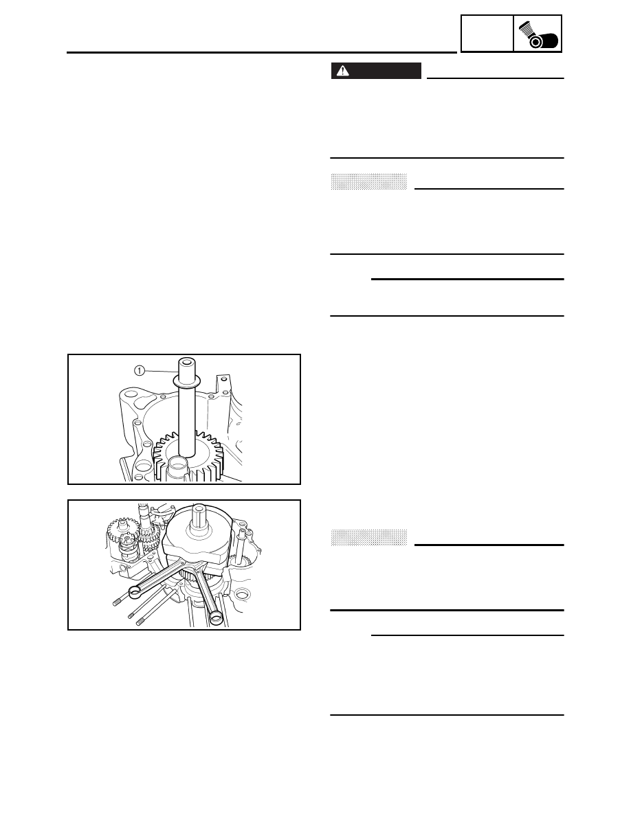
EAS00408

INSTALLING THE CRANKSHAFT

1. Install: 

• generator shaft 

1

2. Install: 

• crankshaft assembly

CAUTION:

To avoid scratching the crankshaft and to
ease the installation procedure, lubricate
the oil seal lips with lithium-soap-based
grease and each bearing with engine oil. 

NOTE:

• Make sure that the generator shaft drive gear

teeth and generator shaft driven gear teeth
mesh correctly.

• Align the right connecting rod with the front

cylinder sleeve hole.

CRANKSHAFT AND CONNECTING RODS

5 - 119

ENG

TRANSMISSION

EAS00419

TRANSMISSION

Order

Job/Part

Q’ty

Remarks

Removing the transmission, shift 
drum assembly, and shift forks 

Remove the parts in the order listed. 

Crankcase

Separate.
Refer to “CRANKCASE”.

1

Shift fork guide bar

2

2

Shift fork “L”

1

3

Shift fork “R”

1

4

Shift fork “C”

1

5

Shift drum assembly

1

6

Drive axle assembly

1

7

Main axle assembly

1

8

Spacer

1

For installation, reverse the removal 
procedure.

5 - 120

ENG

TRANSMISSION

Order

Job/Part

Q’ty

Remarks

Disassembling the main axle 
assembly

Remove the parts in the order listed. 

1

Circlip

1

2

Washer 1

3

5th pinion gear

1

4

2nd/3rd pinon gear

1

5

Circlip

1

6

Washer

1

7

4th pinon gear

1

8

Main axle/1st pinon gear

1

For assembly, reverse the disassembly 
procedure.

5 - 121

ENG

TRANSMISSION

Order

Job/Part

Q’ty

Remarks

Disassembling the drive axle 
assembly

Remove the parts in the order listed. 

1

5th wheel gear

1

2

Circlip 1

3

Washer

1

4

2nd wheel gear

1

5

Circlip

1

6

Washer

1

7

1st wheel gear

1

8

4th wheel gear

1

9

Circlip

1

0

Washer

1

A

3rd wheel gear

1

B

Drive axle

1

For assembly, reverse the disassembly 
procedure.

5 - 122

ENG

TRANSMISSION

EAS00421

CHECKING THE SHIFT FORKS

The following procedure applies to all of the
shift forks.
1. Check: 

• shift fork cam follower 

1


• shift fork pawl 

2


Bends/damage/scoring/wear 

 Replace

the shift fork.

2. Check: 

• shift fork guide bar 

Roll the shift fork guide bar on a flat surface. 
Bends 

 Replace.

WARNING

Do not attempt to straighten a bent shift
fork guide bar. 

3. Check: 

• shift fork movement 

(along the shift fork guide bar) 
Rough movement 

 Replace the shift forks

and shift fork guide bar as a set.

5 - 123

ENG

TRANSMISSION

EAS00422

CHECKING THE SHIFT DRUM ASSEMBLY

1. Check: 

• shift drum grooves 

Damage/scratches/wear 

 Replace the

shift drum assembly. 

• shift drum segment 

1


Damage/wear 

 Replace the shift drum

assembly. 

• shift drum bearing 

2


Damage/pitting 

 Replace the shift drum

assembly.

EAS00425

CHECKING THE TRANSMISSION

1. Measure: 

• main axle runout 

(with a centering device and dial gauge 

1

Out of specification 

 Replace the main

axle.

2. Measure: 

• drive axle runout 

(with a centering device and dial gauge 

1

Out of specification 

 Replace the drive

axle.

Main axle runout limit 

0.08 mm (0.003 in)

Drive axle runout limit 

0.08 mm (0.003 in)

3. Check: 

• transmission gears 

Blue discoloration/pitting/wear 

 Replace

the defective gear(s). 

• transmission gear dogs 

Cracks/damage/rounded edges 

 Replace

the defective gear(s).

5 - 124

ENG

TRANSMISSION

4. Check: 

• transmission gear engagement 

(each pinion gear to its respective wheel
gear) 
Incorrect 

 Reassemble the transmission

axle assemblies.

5. Check: 

• transmission gear movement 

Rough movement 

 Replace the defective

part(s).

6. Check: 

• circlips 

Bends/damage/looseness 

 Replace.

EAS00428

INSTALLING THE TRANSMISSION

1. Install: 

• main axle assembly 

1


• drive axle assembly 

2


• O-ring
• spacer

EAS00426

INSTALLING THE SHIFT FORKS AND 
SHIFT DRUM ASSEMBLY 

1. Install: 

• shift fork “R” 
• shift fork “C” 
• shift fork “L” 
• shift drum assembly 

1


• shift fork guide bars

NOTE:

The embossed marks on the shift forks should
face towards the right side of the engine and
be in the following sequence: “R”, “C”, “L”. 

5 - 125

ENG

TRANSMISSION

2. Check:

• transmission 

Rough movement 

 Repair.

NOTE:

Oil each gear, shaft, and bearing thoroughly. 

6 - 1

FI

FUEL INJECTION SYSTEM

FUEL INJECTION SYSTEM

1

Linear control valve 

2

Intake air pressure sensor 2

3

Intake air temperature sensor

4

Intake air pressure sensor 1

5

Engine temperature sensor

6

Atmospheric pressure sensor

7

Throttle position sensor

8

Spark plug

9

Relay unit

0

ECU

A

Battery

B

Fuel pump

C

Lean angle cut-off switch

D

Oil temperature sensor

E

Decompression solenoid

F

Crankshaft position sensor

G

Cylinder identification sensor

H

Ignition coil

3

2

1

H

G

8

F E D

C

B

A

0

9

8

7

5

4

6

FUEL INJECTION SYSTEM

1

2

3

4

5

6

6 - 2

FI

FUEL INJECTION SYSTEM

WIRING DIAGRAM

B3

B3

R

/

B

L

/

R

R

/

L

R

/

W

(BLACK)

(GRAY)

W

W

W

R

B

B

W

W

W

W

W

W

B

/

W

Br

/

Y

P

/

W

R

/

W

W

/

B

W

/

Y

Y

/

L

G

B

/

L

Y

/

G

Y

/

G

G

P

R

O

B

P

Br

Y

R

/

G

R

/

GG

G

G

G

/

RB

/

L

G

W

L

B

L

W

/

Y

B

/

L

P

P

/

W

L

B

/

L

(BLA

CK)

B
Y
L

(BLA

CK)

L

B

/

L

P

/

Y

(GRA

Y)

L

B

/

L

(BLA

CK)

L

Y

/

G

L

B

/

L

P

/

W

P

/

Y

B

/

L

Br

/

W

L

P

B

Y

L

B

/

L

L

B

/

L

W

G

/

R

B

/

L

Gy

/

R

WG

(GRA

Y)

W

Gy

(D

ARK GRA

Y)

(BLA

CK)

(BLA

CK)

B

/

O

B

/

R

B

/

R

G

/

R

R

/

G

Y

/

G

B

/

L

P

/

L

Y

/

L

Y

/

B

Gy

Gy

G

L

/

R

Lg

Y

/

R

R

/

L

R

/

W

R

/

W

Y

W

/

Y

W

/

G

R

/

B

P

Br

P

/

Y

P

/

W

Br

/

W

Br

/

L

B

/

RB

/

W

B

/

Y

B

/

O

B

/

G

Y

/

RL

/

W

W

/

B

W

L

L

/

B

B3

B3

(BLA

CK)

L

/

G

L

/

R

L

/

G

B

/

Y

B

/

R

B

(BLUE)

Br

/

B

R

/

L

L

/

W1

L

/

R

L

/

Y

L

/

G

Sb

Lg

B

/

R

B

/

Y

L

R

/

L

B

B
B

B

B

L

/

G

B

(BLUE)

B

/

L

Gy

B

B

Gy

B

L

/

Y

R

/

L

Br

/

B

Gy

B

/

L

Sb

Lg

Sb

L

B

/

L

W

/

Y

L

B

/

L

W

/

B

Br

/

W

Br

/

W

Br

/

L

Br

/

L

Br

/

L

B

B

W

L

(BLA

CK)

(BLA

CK)

(BLA

CK)

(BLA

CK)

(BLA

CK)

(BLA

CK)

W

B

Br

B

W

L

B

L

W

/

B

B

/

L

Y

L

B

L

Y

B

P

/

Y

Gy

Br

Br

G

Gy

Lg

Lg

W

B

/

L

B

/

O

(RED)

(RED)

(BLUE)

(BLUE)

Y

/

L

B

L

Br

L

Br

Y

/

L

B

Gy

/

R

Lg

BB

Br

/

Y

O

P

R

P

R

Br

/

Y

O

Gy

L

/

R

B

/

L

L

/

R

B

/

L

G

/

R

Gy

G

/

R

(GREEN)

(GREEN)

B

B

Lg

Lg

Dg

Dg

Br

Br

Y

Y

Ch

Ch

(RED)

(BLUE)

P

R

Br

/

Y

O

Gy

L

/

R

B

/

LG

/

R

Gy

Gy

Br

G

/

R

L

/

R

Br

/

Y

B

/

L

P

R

Y

O

G

/

R

L

/

R

G

G

G

Gy

Gy

Gy

W

W

W

W

W

R

/

B

R

/

B

R

/

G

P

/

L

W

/

G

Br

/

L

R

R

/

G

R

B

B

B

R

R

R

R

R

B

B

R

/

W

R

/

B

R

/

W

RR

L

B

Br

WY

/

R

Br

/

W

B

B

ON

OFF

R

/

B

R

Br

/

L

L

/

B

L

/

Y

R

R

/

B

R

/

B

Gy

/

R

R

Br

/

B

(BLACK)

Y

Br

(BLACK)

B

B

(BLACK)

B

/

GL

/

W1

B

/

R

R

/

W

Y

Br

(BLACK)

R

/

W

B

L

/

W

R

/

B

G

/

Y

Br

(BLACK)

L

/

Y

B

/

YB

/

Y

Ch

Dg

G

Y

(BLUE)

L

/

Y

Ch

Dg

G

Y

(BLUE)

A

A

L

L

L

L

Y

A

B

B

Y

Y

Y

A

Ch

Ch

A

B

B

A

B

B

B

B

Dg

Dg

Dg

Y

Ch

B

B

B

B

G

G

B

Y

R

/

Y

G

/

L

Y

/

B

R

/

Y

Br

W

B

/

W

P

B

B

/

G

B

/

R

R

/

Y

R

/

W

B

/

G

L

/

W1

B

/

R

R

/

W

B

/

YL

/

Y

B

/

Y

B

/

L

P

B

Y

G

B

Ch

Dg

B

/

Y

G

/

L

Y

/

B

Y

/

R

Y

/

R

R

/

Y

R

/

Y

Br

/

W

Br

/

W

L

/

Y

Y

/

R

G

/

L

P

Br

/

W

B

R

/

Y

Y

/

R

P

Br

/

W

B

Lg

Br

Ch

Dg

L

/

B

L

/

W

Y

/

B

G

/

R

Y

/

L

Y

/

R

B

/

W

R

/

G

P

/

L

W

/

G

Br

/

L

R

/

G

P

/

L

W

/

G

Br

/

L

R

/

B

R

/

B

L

/

W1

L

B

/

L

B

/

L

L

B

R

Br

Br

L

L

Dg

Ch

B

B

B

B

B

B

L

Br

R

/

G

L

9

0

A

(L)

N (R)

Y

Ch

LB

Dg

Ch

Y

L

B

Dg

12

3

4

5

6

7

F

E

B

C

D

L

G

H

I

J

K

M

N

O

P

Q

R

R

S

S

T

U

V

W

Z

X

Y

[

\

]

^

a

b

c

d

e

f

g

h

i

j

k

l

q

m

n

o

p

r

s

t

u

v

w

y

x

z

{

|

}

~

å

8

A

WIREHARNESS

TAIL SUB-WIREHARNESS

B

B

R

/

L

G

R

L

/

B

Br

/

L

L

/

Y

R

L

/

B

Br

/

L

L

/

Y

(BLACK)

W

G

W

G

/

Y

W

G

/

Y

W

G

(BLACK)

(BLACK)

Br

P

B

WIREHARNESS

INJECTION SUB-WIREHARNESS

6 - 3

FI

FUEL INJECTION SYSTEM

3

Main switch 

4

Battery

6

Main fuse 

A

Fuel injection system relay

B

Fuel pump

E

Crankshaft position sensor

F

Throttle position sensor

G

Intake air pressure sensor 1 

H

Intake air pressure sensor 2 

I

Atmospheric pressure sensor

J

Cylinder identification sensor

K

Lean angle cut-off switch

L

Speed sensor

M

Intake air temperature sensor

N

Engine temperature sensor

O

Oil temperature sensor

P

ECU

Q

Linear control valve 

U

Cylinder #1-injector

V

Cylinder #2-injector

u

Engine stop switch

{

Ignition fuse

~

ECU fuse

å

Fuel injection system fuse

6 - 4

FI

FUEL INJECTION SYSTEM

ECU’S SELF-DIAGNOSTIC FUNCTION

The ECU is equipped with a self-diagnostic function in order to ensure that the engine control sys-
tem is operating normally. If this function detects a malfunction in the system, it immediately oper-
ates the engine under substitute characteristics and illuminates the engine trouble warning light to
alert the rider that a malfunction has occurred in the system. Once a malfunction has been detected,
it becomes stored in the ECU memory in the form of a fault code.

ECU’s mode function

The ECU is equipped with a diagnosis mode, in addition to the normal mode in which the ECU oper-
ates normally.

Normal mode
• To check whether the warning light bulb is blown, the warning light illuminates for 1.4 seconds

after the main switch has been turned ON, and while the starter switch is being pressed.

• To inform the rider that the fuel injection stop function is active, the warning light blinks while the

start switch is being pressed to start the engine.

• If a malfunction in the system is detected by the self-diagnostic function, this mode provides an

appropriate substitute characteristic operation, and alerts the rider of the detected malfunction by
illuminating a warning light.

• After the engine has been stopped, digital numbers representing the self-diagnostic fault codes

appear on the clock LCD. Once a self-diagnostic fault code has been displayed, it remains stored
in the ECU memory until a deletion operation is performed.

Diagnosis mode
• In this mode, diagnostic codes are input into the ECU in accordance with the number of times the

start switch has been operated.

• In accordance with the diagnostic codes, the ECU displays the values received from the sensors

and actuates the actuators.

• Whether or not the system is operating normally is determined by a human operator through the

observations of the values indicated by the engine trouble warning light or the actuating conditions
of the actuators.

6 - 5

FI

FUEL INJECTION SYSTEM

Engine trouble warning light indication and FI system operating conditions (normal mode)

Warning light 

indication

ECU’s operating 

condition

FI operating condition

Starting and driving

ON and OFF *1

Self-diagnostic func-
tion in operation

FI function in operation Able

Blinking *2

Warning control when 
unable to start engine

Operation stopped

Unable

Continuous ON

Detecting malfunction

Gives driving instruc-
tions with substitute 
characteristics in accor-
dance with the descrip-
tion of the malfunction.

Able/Unable depend-
ing on self-diagnostic 
fault code

OFF *3

Possibly a blown warn-
ing light bulb or a mal-
function in power 
supply system or ECU

*1
The warning light illuminates 1.4 seconds each
time the main switch is turned ON. The ECU
performs a self diagnosis during this time and
turns OFF the light thereafter.

*2
Warning control when unable to start engine
This control is effected when any one of the
conditions listed below is present and the
starter switch is turned ON:
a. Battery voltage below the specified value

(defective Fuel injection system relay,
engine stop switch turned OFF, or drained
battery)

b. One of the fault codes listed below has

been detected (self-diagnostic code 12, 19,
30, 41, or 50 is output):
(12: faulty crankshaft position sensor sig-
nal)
(19: open circuit in sidestand input line)
(30: a fall has been detected)
(41: open or short circuit in lean angle cut-
off switch)
(50: ECU memory check error)

Main switch
OFF

Main switch
ON

Light ON for 
1.4 seconds

Light 
OFF

Light 
OFF

Initialize

Engine trouble 
warning light

6 - 6

FI

FUEL INJECTION SYSTEM

*3
Function to check for blown warning light bulb
The engine trouble warning light illuminates 

1

for 1.4 seconds after the main switch has been
turned  “ON” and while the starter switch is
being pressed. If the warning light does not
illuminate under these conditions, a problem
may have possibly occurred, such as a blown
warning light bulb. Therefore, take an appropri-
ate corrective action by referring to the trouble-
shooting section.

1

Determining the area of the malfunction through the self-diagnostic fault code number

The possible location of the system in which a problem may be occurring can be determined by
observing the self-diagnostic fault code number that appears on the tachometer and cross-referenc-
ing it on the fault code number table. When used in conjunction with the troubleshooting details, and
by checking the possible items one by one, you will be able to identify the cause of the problem in
order to carry out an accurate repair work.

Warning of the occurrence of a malfunction appears on the tachometer.

Determine the area of the problem by referring to the self-diagnostic fault code number.

Turn off the main switch.

Repair the problem area by referring to the troubleshooting details.

Turn “ON” the main switch in order to revert to normal operation, and erase the fault code from 

memory. (Once a fault code is detected by the ECU, it remains stored in the ECU memory even 

after the main switch has been turned “OFF”.)

6 - 7

FI

FUEL INJECTION SYSTEM

* Table of self-diagnostic fault code numbers displayed on meter

• How to erase the self-diagnostic fault code from memory:

If the ECU detects a normal signal upon the completion of the repair of the malfunction, the self-
diagnostic fault code disappears from the meter and is replaced by the normal clock display. How-
ever, the self-diagnostic fault code of the previous malfunction remains in the ECU memory as
part of the malfunction history. To erase the self-diagnostic fault code from the malfunction history,
the operation for diagnostic code 62 must be performed in the diagnosis mode.

No.

Symptom

Able/

unable to 

start

Able/

unable to 

drive

No.

Symptom

Able/

unable to 

start

Able/

unable to 

drive

11

No normal signals are received 
from the cylinder identification 
sensor.

Able

Able

26

Faulty intake air pressure sensor 
pipe system 2; a hose is 
detached, causing the constant 
application of atmospheric pres-
sure to the sensor; or, the hose is 
clogged.

Able

Able

12

No normal signals are received 
from the crankshaft position sen-
sor.

Unable

Unable

27

Oil temperature sensor - open or 
short circuit detected.

Able

Able

13

Intake air pressure sensor 1 - 
open or short circuit detected.

Able

Able

28

Engine temperature sensor - 
open or short circuit detected.

Able

Able

14

Faulty intake air pressure sensor 
pipe system 1; a hose is 
detached, causing the constant 
application of atmospheric pres-
sure to the sensor; or, the hose is 
clogged.

Able

Able

29

Decompression thermostat - 
open or short circuit detected.

Able

Able

15

Throttle position sensor - open or 
short circuit detected.

Able

Able

30

The motorcycle has overturned.

Unable

Unable

16

A stuck throttle position sensor is 
detected.

Able

Able

37

Linear control valve - faulty valve 
or motor is detected.

Able

Able

19

Open circuit is detected in the 
input line from the sidestand 
switch to the ECU.

Unable

Unable

38

Decompression solenoid - open 
circuit is detected.

Able

Able

20

Atmospheric pressure sensor or 
intake air pressure sensor
Malfunction of the atmospheric 
pressure sensor in the intermedi-
ate electrical potential.
Malfunction of the intake air pres-
sure sensor in the intermediate 
electrical potential.

Able

Able

41

Lean angle cut-off switch - open 
or short circuit detected.

Unable

Unable

22

Intake temperature sensor - open 
or short circuit detected.

Able

Able

42

No normal signals are received 
from the speed sensor; or, an 
open or short circuit is detected in 
the neutral switch.

Able

Able

23

Atmospheric pressure sensor - 
open or short circuit detected.

Able

Able

43

The ECU is unable to monitor the 
battery voltage (an open circuit in 
the line to the ECU).

Able

Able

25

Intake air pressure sensor 2 - 
open or short circuit detected.

Able

Able

50

Faulty ECU memory. When this 
malfunction is detected, the code 
number might not appear on the 
meter.

Unable

Unable

6 - 8

FI

FUEL INJECTION SYSTEM

SUBSTITUTE CHARACTERISTICS OPERATION CONTROL (FAIL-SAFE ACTION)

If the ECU detects an abnormal signal from a sensor while the motorcycle is being driven, the ECU
illuminates the engine trouble warning light and provides the engine with substitute characteristic
operation instructions that are appropriate for the type of the malfunction.
When an abnormal signal is received from a sensor, the ECU processes the specified values that
are programmed for every sensor, in order to provide the engine with substitute characteristics
operation instructions that enable the engine to continue to operate (or to stop its operation,
depending on circumstances).
The ECU takes fail-safe actions in two ways: one in which the sensor output is set to a prescribed
value, and the other in which the ECU directly operates an actuator. Details on the fail-safe actions
are given in the table below.

Table of substitute characteristic operation control by self-diagnostic fault code

Code No.

Item

Fail-safe action

Able/unable to 

start

Able/unable to 

drive

11

Cylinder identification 
sensor

• Continues to operate the engine based on the 

results of the cylinder identification that existed up 
to that point.

Able

Able

12

Crankshaft position sen-
sor

• Stops the engine (by stopping the injection and 

ignition).

Unable

Unable

13
14
25
26

Intake air pressure sensor 
(open or short circuit) 
(pipe system)

• Fixes the intake air pressure to 760 mmHg.

Able

Able

15
16

Throttle position sensor 
(open or short circuit) 
(stuck)

• Fixes the throttle position sensor to fully open.

Able

Able

19

Sidestand switch 
(open circuit in wire to 
ECU)

-- (No start)

Unable

Unable

20

Atmospheric pressure 
sensor or intake air pres-
sure sensor

• Fixes the atmospheric correction value to 0 mmHg.

Able

Able

22

Intake temperature sen-
sor

• Fixes the intake temperature to 15 °C (59 °F).

Able

Able

23

Atmospheric pressure 
sensor

• Fixes the atmospheric pressure to 760 mmHg.

Able

Able

27

Oil temperature sensor

• Fixes the oil temperature to 80 °C (176 °F).

Able

Able

28

Engine temperature sen-
sor

• Fixes the engine temperature to 140 °C (284 °F).

Able

Able

29

Decompression thermo-
stat

• Electricity is not circulated to the decompression 

solenoid and the thermostat is not operated.

Able

Able

37

Linear control valve

--

Able

Able

38

Decompression solenoid

--

Able

Able

30
41

Lean angle cut-off switch 
(latch up detected) 
(open or short circuit)

• Turns OFF the fuel injection system relay of the fuel 

system.

Unable

Unable

42

Speed sensor, neutral 
switch

• Fixes the gear to the top gear.

Able

Able

43

Fuel system voltage 
(monitor voltage)

• Fixes the battery voltage to 12 V.

Able

Able

50

ECU internal malfunction 
(memory check error)

--

Unable

Unable


Content      ..     23      24      25      26     ..