Yamaha XVS1100 (L). Service Manual - part 20
 

  Index      Manuals     Yamaha XVS1100 (L). Service Manual


Search            copyright infringement  


Content      ..     18      19      20      21     ..


Yamaha XVS1100 (L). Service Manual - part 20


7-12

IGNITION SYSTEM

ELEC

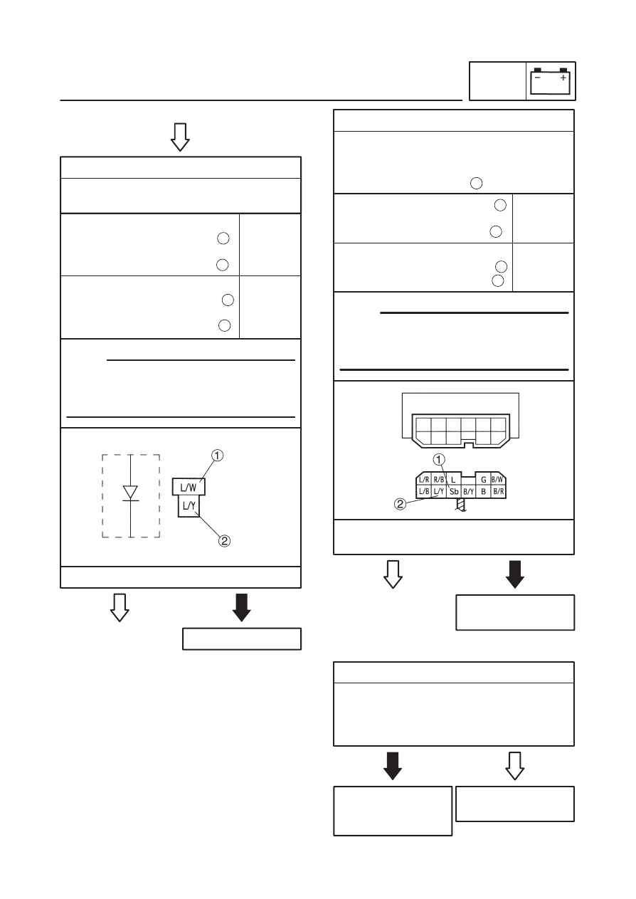
12. Diode

S

Remove the diode from the wire harness.

S

Check for continuity as follows:

14. Wiring

S

Check the entire ignition system’s wiring.
Refer to “CIRCUIT DIAGRAM”.

S

Is the ignition system’s wiring properly con-
nected and without defects?

EAS00754

:

Tester (+) lead 


Blue / White 

Tester (–) lead 


Blue / Yellow 

1

2

Tester (+) lead 


Blue / Yellow 

Tester (–) lead 


Blue / White 

2

1

Continu-
ity

No Con-
tinuity

YES

Replace the diode.

NO

NOTE:

When you switch the “–” and “+” leads of the
digital pocket tester the readings in the above
chart will be reversed.

S

Is the diode OK?

YES

Properly connect or
repair the ignition
system’s wiring.

NO

Replace the ignitor
unit.

13. Starting circuit cut-off relay (diode)

S

Remove the relay unit from the wire har-
ness.

S

Check for continuity as follows:
Sky blue – Blue / Yellow 

2

Tester (+) lead 

 SKy blue 

Tester (–) lead 


Blue / Yellow 

1

2

Tester (+) lead 


Blue / Yellow 

Tester (–) lead 

 Sky blue

2

1

Continu-
ity

No Con-
tinuity

YES

Replace the starting
circuit cut-off relay.

NO

NOTE:

When you switch the “–” and “+” leads of the
digital pocket tester the readings in the above
chart will be reversed.

S

Is the starting circuit cut-off relay (diode)
OK?

7-13

4

5

6

7

8

9

10

13

20

29

37

Main switch

Alarm system (option)

Ignition fuse

Battery

Main fuse

Starter relay

Starter motor

Starting circuit cut of

f relay

Neutral switch

Sidestand switch

Start switch

Clutch switch

Engine stop switch

36

38

Diode

60

ELECTRIC STARTING SYSTEM

ELEC

EB803000

ELECTRIC STARTING SYSTEM

CIRCUIT DIAGRAM

7-14

ELECTRIC STARTING SYSTEM

ELEC

EB803010

STARTING CIRCUIT OPERATION
The starting circuit on this model consists of the
starter motor, starter relay, and the starting cir-
cuit cut-off relay. If the engine stop switch is on
“RUN” and the main switch is on “ON” (both
switches are closed), the starter motor can op-
erate only if:

The transmission is in neutral (the neutral
switch is closed).

or if

The clutch lever is pulled to the handlebar
(the clutch switch is closed) and the side-
stand is up (the sidestand switch is closed).

The starting circuit cut-off relay prevents the
starter from operating when neither of these
conditions have been met. In this instance, the
starting circuit cut-off relay is open so current
cannot reach the starter motor.

When at least one of the above conditions have
been met however, the starting circuit cut-off
relay is closed, and the engine can be started by
pressing the starter switch.

WHEN THE TRANSMISSION IS IN
NEUTRAL

WHEN THE SIDESTAND IS UP AND
THE CLUTCH LEVER IS PULLED IN

1 Battery

2 Main fuse

3 Main switch

4 Ignition fuse

5 Engine stop switch

6 Starting circuit cut-off relay

7 Diode

8 Clutch switch

9 Sidestand switch

10

Neutral switch

11

Start switch

12

Starter relay

13

Starter motor

7-15

ELECTRIC STARTING SYSTEM

ELEC

2. Battery

S

Check the condition of the battery.
Refer to “CHECKING AND CHARGING
THE BATTERY” in chapter 3.

Open-circuit voltage

12.8 V or more at 20 

_

C

S

Is the battery OK?

YES

S

Clean the battery
terminals.

S

Recharge or re-
place the battery.

NO

3. Starter motor

S

Connect the battery positive terminal 
and starter motor lead 

 with a jumper lead

.

YES

Repair or replace the
starter motor.

NO

EAS00758

1

3

2

S

A wire that is used as a jumper lead
must have at least the same capacity of
the battery lead, otherwise the jumper
lead may burn.

S

This check is likely to produce sparks,
therefore make sure that no flammable
gas or fluid is in the vicinity.

S

Does the starter motor turn?

WARNING

NOTE:

YES

NO

Replace the fuse(-s).

1. Main and ignition fuses

S

Check the main and ignition fuses for conti-
nuity.
Refer to “CHECKING THE FUSES” in chap-
ter 3.

S

Are the main and ignition fuses OK?

EAS00757

EAS00739

TROUBLESHOOTING

The starter motor fails to turn.

Check:

1. main and ignition fuses
2. battery
3. starter motor
4. starting circuit cutoff relay
5. starting circuit cutoff relay (diode)
6. starter relay
7. main switch
8. engine stop switch
9. neutral switch

10. sidestand switch
11. clutch switch
12. start switch
13. diode
14. wiring

(of the entire starting system)

S

Before troubleshooting, remove the following
part(-s):

1) battery cover
2) rider’s seat
3) fuel tank
4) steering head side covers
5) left side cover

S

Troubleshoot with the following special
tool(-s).

Pocket tester

90890-03112

EAS00738

7-16

4. Starting circuit cutoff relay

Disconnect the relay unit from the coupler.

Connect the pocket tester (


 1) and bat-

tery (12V) to the relay unit terminals as
shown.

YES

Replace the relay
unit.

NO

Battery positive terminal 


red / black 

Battery negative terminal 


black / yellow 

1

2

Tester positive probe 

 blue 

Tester negative probe 

 black

3

4

Does the starting circuit cutoff relay have
continuity between black and blue / white?

5. Starting circuit cutoff relay (Diode)

Disconnect the starting circuit cutoff relay
from the coupler.

Connect the pocket tester (


 1) to the

starting circuit cutoff relay terminals as
shown.

Measure the starting circuit cutoff relay for
continuity as follows.

YES

Replace the relay
unit.

NO

Tester positive probe 


sky blue

Tester negative probe 

black / yellow

1

2

Continuity

NOTE:

When you switch the “–” and “+” leads of the
digital pocket tester the readings in the above
chart will be reversed.

Are the tester readings correct?

EAS00760

Tester positive probe 

black / yellow

Tester negative probe 

sky blue

2

1

No
continuity

ELECTRIC STARTING SYSTEM

ELEC

EAS00759

7-17

YES

Replace the starter
relay.

NO

Battery positive terminal 

 red / white

Battery negative terminal 

 blue

2

EAS00750

Check the engine stop switch for continuity.
Refer to “CHECKING THE SWITCHES”.

Is the engine stop switch OK?

YES

Replace the right
handlebar switch.

NO

8. Engine stop switch

EAS00751

Check the neutral switch for continuity.
Refer to “CHECKING THE SWITCHES”.

Is the neutral switch OK?

YES

Replace the neutral
switch.

NO

9. Neutral switch

EAS00752

Check the sidestand switch for continuity.
Refer to “CHECKING THE SWITCHES”.

Is the sidestand switch OK?

YES

Replace the side-
stand switch.

NO

10. Sidestand switch

EAS00763

Check the clutch switch for continuity.
Refer to “CHECKING THE SWITCHES”.

Is the clutch switch OK?

YES

Replace the clutch
switch.

NO

11. Clutch switch

1

Tester positive probe 

 red 

Tester negative probe 

 black

3

4

Does the starter relay have continuity be-
tween red and black?

EAS00749

Check the main switch for continuity.
Refer to “CHECKING THE SWITCHES”.

Is the main switch OK?

YES

Replace the main
switch.

NO

7. Main switch

6. Starter relay

Disconnect the starter relay from the cou-
pler.

Connect the pocket tester (


 1) and bat-

tery (12 V) to the starter relay coupler as
shown.

ELECTRIC STARTING SYSTEM

ELEC

EAS00761

7-18

EAS00766

NO

The starting system
circuit is OK.

YES

YES

Replace the right
handlebar switch.

NO

Properly connect or
repair the starting
system’s wiring.

12. Start switch

Check the start switch for continuity.
Refer to “CHECKING THE SWITCHES”.

Is the start switch OK?

14. Wiring

Check the entire starting system’s wiring.
Refer to “CIRCUIT DIAGRAM”.

Is the starting system’s wiring properly con-
nected and without defects?

YES

Replace the diode.

NO

13. Diode

Check the diode for continuity.
Refer to “IGNITION SYSTEM”.

Is the diode OK?

ELECTRIC STARTING SYSTEM

ELEC

EAS00764

1
2

1
2
3
4
5
6
7
8
9

10

11

Order

Job name / Part name

Q’ty

Remarks

Removing the starter motor
Starter motor lead
Starter motor assembly

Disassembling the starter motor
Circlip
Starter motor drive gear
Starter motor rear cover
Washer set
Starter motor front cover
Washer set
End bracket
Planetary gears
Armature assembly
Brush holder / brush
Starter motor yoke

1
1

1
1
1
1
1
1
1
2
1

1/1

1

Remove the parts in the order listed.

For installation, reverse the removal
procedure.

Disassembly the pats in the order listed.

Refer to “Assembling the starter motor.”

Refer to “Assembling the starter motor.”

Refer to “Assembling the starter motor.”

For assembly, reverse the disassembly
procedure

10 Nm (1.0 m

kg)

Refer to “Assembling the starter motor.”

ELECTRIC STARTING SYSTEM

ELEC

7-19

STARTER MOTOR

7-20

ELECTRIC STARTING SYSTEM

ELEC

NOTE:

EAS00769

Checking the starter motor
1. Check:

S

commutator
Dirt 

 Clean with 600 grit sandpaper.

2. Measure:

S

commutator diameter 

a

Out of specification 

 Replace the starter

motor.

Min. commutator diameter

27 mm

3. Measure:

S

mica undercut 

a

Out of specification 

 Scrape the mica to the

proper measurement with a hacksaw blade
which has been grounded to fit the commuta-
tor.

Mica undercut

0.7 mm

The mica must be undercut to ensure proper op-
eration of the commutator.

4. Measure:

S

armature assembly resistances (commuta-
tor and insulation)
Out of specification 

 Replace the starter

motor.

a. Measure  the armature assembly resis-

tances with the pocket tester.

Pocket tester

90890-03112

Armature assembly

Armature coil resistance 

1

0.026 

X

 0.034 

 at 20 

_

C

Insulation resistance 

2

Above 1 M

 at 20 

_

C

b. If any resistance is out of specification, re-

place the starter motor.

7-21

ELECTRIC STARTING SYSTEM

ELEC

NOTE:

NOTE:

5. Measure:

brush length 

a

Out of specification 

 Replace the brushes

as a set.

Min. brush length

5 mm

6. Measure:

brush spring force
Out of specification 

 Replace the brush

springs as a set.

Bruch spring force

7.65 

X

 10.01 N (780 

X

 1.020 g)

7. Check:

gear teeth
Damage / wear 

 Replace the gear.

8. Check:

oil seal
Damage / wear 

 Replace the defective

part(-s).

EAS00772

Assembling the starter motor
1. Install:

brush holder 

1

Align the tab 

a

 on the brush holder with the slot

in the starter motor rear cover.

2. Install:

starter motor yoke 

1

end bracket 

2

starter motor front cover 

3

Align the projection 

a

on the front cover with the

slot 

b

 on the end cover and starter motor yoke.

7-22

ELECTRIC STARTING SYSTEM

ELEC

NOTE:

3. Install:

Starter motor rear cover 

1

Align the match marks 

a

 on the rear cover with

the match marks 

b

 on the front cover.

7-23

CHARGING SYSTEM

ELEC

AC magneto (stator coil)
Rectifier / regulator
Battery
Main fuse

2
3
7
8

EB804000

CHARGING SYSTEM

CIRCUIT DIAGRAM

CHARGING SYSTEM

ELEC

2. Battery

S

Check the condition of the battery.
Refer to “CHECKING AND CHARGING THE
BATTERY” in chapter 3.

Open-circuit voltage

12.8 V or more at 20

_

C

S

Is the battery OK

YES

S

Clean the battery
terminals.

S

Recharge or re-
place the battery.

NO

EAS00775

3. Charging voltage

S

Connect the engine tachometer to the spark
plug lead of cylinder #1.

S

Connect the pocket tester (DC 20 V) to the
battery as shown.

Charging voltage

14 V at 5,000 r / min

Tester positive probe 

battery positive terminal

Tester negative probe 

battery negative terminal

S

Start the engine and let it run at approximate-
ly 5,000 r / min.

S

Measure the charging voltage.

7-24

NOTE:

YES

NO

Replace the fuse.

1. Main fuse

S

Check the main fuse for continuity.
Refer to “CHECKING THE FUSES” in chap-
ter 3.

S

Is the main fuse OK?

EAS00774

EAS00739

TROUBLESHOOTING

The battery is not being sharged.

Check:
1. main fuses
2. battery
3. charging voltage
4. startor coil assembly resistance
5. wiring

(of the entire charging system)

S

Before troubleshooting, remove the following
part(-s):

1) battery cover
2) rider’s seat
3) left side cover

S

Troubleshoot with the following special
tool(-s).

Engine tachometer

90890-03113

Pocket tester

90890-03112

EAS00738

7-25

NO

The charging circuit
is OK.

YES

NOTE:

Make sure that the battery is fully charged.

S

Is the charging voltage within specification?

EAS00776

4. Stator coil assembly resistances

S

Remove the generator cover.

S

Connect the pocket tester (


 1) to the sta-

tor coil assembly coupler as shown.

Stator coil resistance

0.36 

X

 0.44 

 at 20

_

C

S

Is the stator coil assembly OK?

YES

Replace the stator
coil assembly.

NO

Tester positive probe 

 White 

Tester negative probe 

 white

1
2

S

Measure the stator coil assembly resis-
tances.

Tester positive probe 

 white 

Tester negative probe 

 white

1
3

5. Wiring

NO

Replace the rectifi-
er / regulator.

YES

EAS00779

S

Check the wiring connections of the entire
charging system.
Refer to “CIRCUIT DIAGRAM”.

S

Is the charging system’s wiring properly con-
ected and without defects?

Properly connect or
repair the charging
system’s wiring.

CHARGING SYSTEM

ELEC

LIGHTING SYSTEM

ELEC

7-26

49

46

4

7

8

25

27

48

44

50

52

Auxiliary light

Pass switch

Main switch

Battery

Main fuse

Meter light

High beam indicator

Headlight

Dimmer switch

T

ail/brake light

Headlight fuse

Light switch

39

EB805000

LIGHTING SYSTEM

CIRCUIT DIAGRAM

7-27

LIGHTING SYSTEM

ELEC

Open-circuit voltage

12.8 V or more at 20

_

C

YES

Replace the fuse(-s).

NO

YES

S

Clean the battery
terminals.

S

Recharge or re-
place the battery.

NO

Replace the main
switch.

NO

EAS00749

3. Main switch

S

Check the main switch for continuity.
Refer to “CHECKING THE SWITCHES”.

S

Is the main switch OK?

YES

1. Main, and headlight fuses

S

Check the main, and headlight fuses for con-
tinuity.
Refer to “CHECKING THE FUSES” in chap-
ter 3.

S

Are the main, and headlight fuses OK?

2. Battery

S

Check the condition of the battery.
Refer to “CHECKING AND CHARGING
THE BATTERY” in chapter 3.

S

Is the battery OK?

NO

EAS00783

4. Lights switch (for Europe)

S

Check the lights switch for continuity.
Refer to “CHECKING THE SWITCHES”.

S

Is the lights switch OK?

YES

The lights switch is
faulty. Replace the
right handlebar
switch.

NOTE:

EAS00781

EAS00739

TROUBLESHOOTING

Any of the following fail to light: headlight,
high beam indicator light, taillight, auxilia-
ry light (for Europe) or meter light.

Check:
1. main and headlight fuses
2. battery
3. main switch
4. lights switch (for Europe)
5. dimmer switch
6. pass switch
7. wiring

(of the entire charging system)

S

Before troubleshooting, remove the following
part(-s).

1) battery cover
2) rider’s seat
3) fuel tank
4) steering head side covers
5) headlight lens unit
6) tool box cover

S

Troubleshoot with the following special
tool(-s).

Pocket tester

90890-03112

EAS00738


Content      ..     18      19      20      21     ..