Yamaha XVS1100 (L). Service Manual - part 16
 

  Index      Manuals     Yamaha XVS1100 (L). Service Manual


Search            copyright infringement  


Content      ..     14      15      16      17     ..


Yamaha XVS1100 (L). Service Manual - part 16


6-39

FRONT AND REAR BRAKES

CHAS

30 Nm (3.0 m

kg)

WARNING

CAUTION:

23 Nm (2.3 m

kg)

WARNING

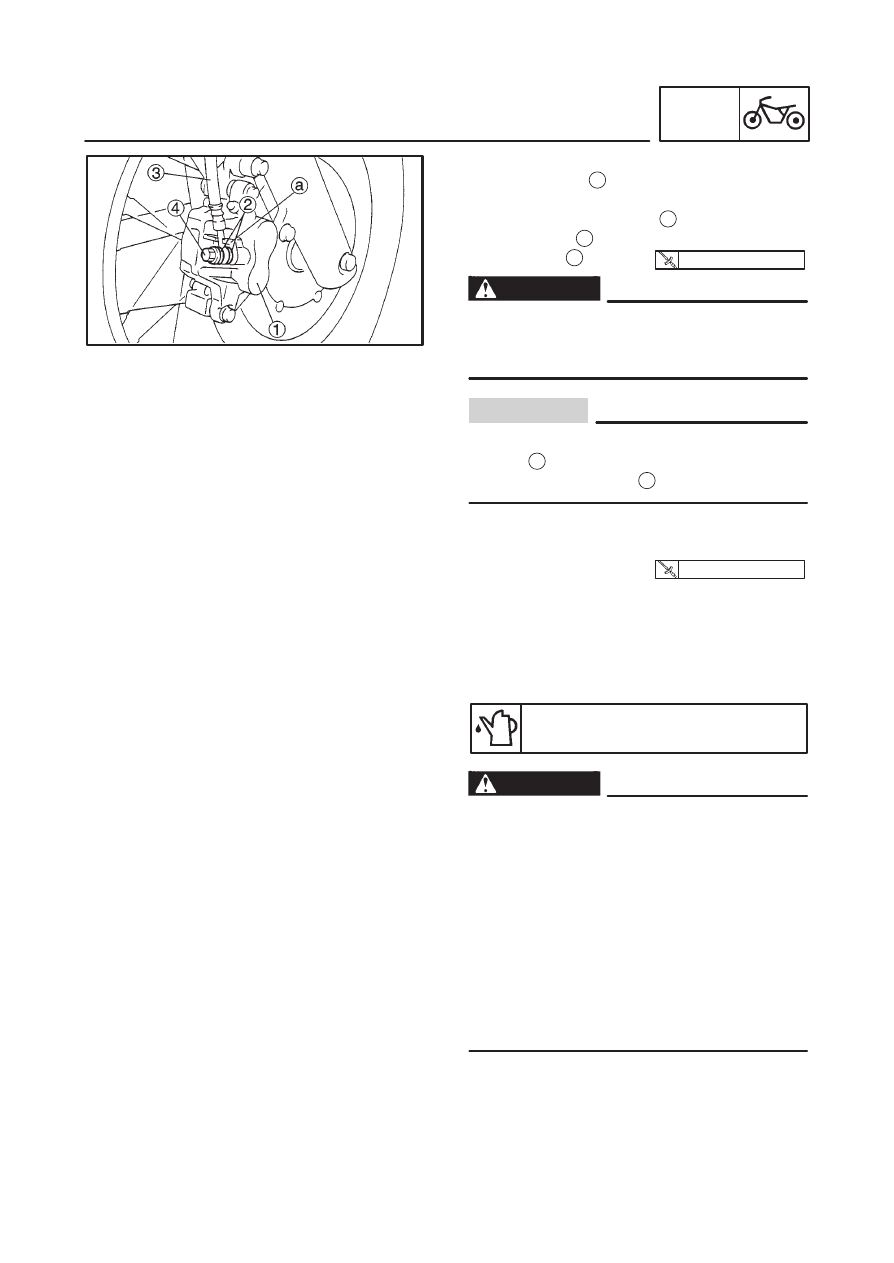
1. Install:

brake caliper 

1

(temporarily)

copper washers (New) 

2

brake hose 

3

union bolt 

4

Proper brake hose routing is essential to in-
sure safe motorcycle operation. Refer to
“CABLE ROUTING”.

When installing the brake hose onto the brake
caliper 

1

, make sure that the brake pipe

touches the projection 

a

 on the brake caliper.

2. Install:

brake caliper retaining bolt

brake hose holder
Refer to “FRONT BRAKE PADS”.

3. Fill:

brake master cylinder reservoir
(with the specified amount of the recom-
mended brake fluid)

Recommended brake fluid

DOT 4

Use only the designated brake fluid. Other
brake fluids may cause the rubber seals to
deteriorate, causing leakage and poor
brake performance.

Refill with the same type of brake fluid that is
already in the system. Mixing brake fluids
may result in a harmful chemical reaction,
leading to poor brake performance.

When refilling, be careful that water does
not enter the reservoir. Water will signifi-
cantly lower the boiling point of the brake
fluid and could cause vapor lock.

FRONT AND REAR BRAKES

CHAS

6-40

CAUTION:

WARNING

Brake fluid may damage painted surfaces
and plastic parts. Therefore, always clean
up any spilt brake fluid immediately.

4. Bleed:

brake system
Refer to “BLEEDING THE HYDRAULIC
BRAKE SYSTEM” in chapter 3.

5. Check:

brake fluid level
Below the minimum level mark 

a


 Add the

recommended brake fluid to the proper level.
Refer to “CHECKING THE BRAKE FLUID
LEVEL” in chapter 3.

6. Check:

brake lever operation
Soft or spongy feeling 

 Bleed the brake

system.
Refer to “BLEEDING THE HYDRAULIC
BRAKE SYSTEM” in chapter 3.

EAS00642

INSTALLING THE REAR BRAKE CALIPER

Before installaiton, all internal brake com-
ponents should be cleaned and lubricated
with clean or new brake fluid.

Never use solvents on internal brake com-
ponents as they will cause the piston seals
to swell and distort.

Whenever a brake caliper is disassembled,
replace the brake caliper piston seals.

Recommended brake fluid

DOT 4

6-41

FRONT AND REAR BRAKES

CHAS

30 Nm (3.0 m

kg)

WARNING

CAUTION:

40 Nm (4.0 m

kg)

WARNING

1. Install:

brake caliper 

1

(temporarily)

copper washers 

New

brake hose 

2

union bolt 

3

Proper brake hose routing is essential to in-
sure safe motorcycle operation. Refer to
“CABLE ROUTING”.

When installing the brake hose onto the
brake caliper 

1

, make sure that the brake

pipe 

a

 touches the projection 

b

 on the cop-

per washer.

2. Install:

brake caliper

brake hose holder
Refer to “REAR BRAKE PADS”.

3. Fill:

brake fluid reservoir
(with the specified amount of the recom-
mended brake fluid)

Recommended brake fluid

DOT 4

Use only the designated brake fluid. Other
brake fluids may cause the rubber seals to
deteriorate, causing leakage and poor
brake performance.

Refill with the same type of brake fluid that
is already in the system. Mixing brake
fluids may result in a farmful chemical
reaction, leading to poor brake perfor-
mance.

When refilling, be careful that water does
not enter the brake fluid reservoir. Water
will signicantly lower the boiling point of
the brake fluid and could cause vapor lock.

FRONT AND REAR BRAKES

CHAS

6-42

CAUTION:

NOTE:

Brake fluid may damage painted surfaces
and plastic parts. Therefore, always clean
up any spilt brake fluid immediately.

4. Bleed:

brake system

Place the motorcycle on a suitable stand.

Make sure that the motorcycle is upright.

Refer to “BLEEDING THE HYDRAULIC
BRAKE SYSTEM” in chapter 3.

5. Check:

brake fluid level
Below the minimum level mark 

a


 Add the

recommended brake fluid to the proper level.
Refer to “CHECKING THE BRAKE FLUID
LEVEL” in chapter 3.

6. Check:

brake pedal operation
Soft or spongy feeling 

 bleed the brake sys-

tem.
Refer to “BLEEDING THE HYDRAULIC
BRAKE SYSTEM” in chapter 3.

6-43

Order

Job name / Part name

Q’ty

Remarks

1
2
3
4
5
6
7
8

Removing the front fork
Front wheel

Brake hose holders
Brake caliper assembly
Front fender
Turn signal light bolts
Upper bracket bolts
Cap bolts
Lower bracket bolts
Front fork legs

2
2
1
2
2
2
2
2

Remove the parts in the order listed.
Refer to “FRONT WHEEL AND BRAKE
DISCS”.

For installation, reverse the removal
procedure.

Refer to “REMOVING / INSTALLING
THE FRONT FORK LEGS”.

20 Nm (2.0 m

kg)

7 Nm (0.7 m

kg)

30 Nm (3.0 m

kg)

10 Nm (1.0 m

kg)

40 Nm (4.0 m

kg)

FRONT FORK

CHAS

FRONT FORK

Order

Job name / Part name

Q’ty

Remarks

Disassembling the front fork
Cap bolt
O-ring
Spacer
Spring seat
Fork spring
Dust seal
Oil seal clip
Damper rod bolt
Copper washer
Damper rod / rebound spring
Oil seal

1
1
1
1
1
1
1
1
1

1 / 1

1

Disassemble the parts in the order listed.

Refer to “DISASSEMBLING / ASSEM-
BLING THE FRONT FORK LEGS”.

1
2
3
4
5

9

6
7
8

10

11

23 Nm (2.3 m

kg)

30 Nm (3.0 m

kg)

FRONT FORK

CHAS

6-44

6-45

Order

Job name / Part name

Q’ty

Remarks

Seal spacer
Outer tube bushing
Inner tube / inner tube bushing
Oil lock piece
Outer tube

1
1

1 / 1

1
1

For assembly, reverse the disassembly
procedure.

Refer to “DISASSEMBLING / ASSEM-
BLING THE FRONT FORK LEGS”.

12

13

14

15

16

23 Nm (2.3 m

kg)

30 Nm (3.0 m

kg)

FRONT FORK

CHAS

6-46

FRONT FORK

CHAS

WARNING

NOTE:

WARNING

CAUTION:

EAS00649

REMOVING THE FRONT FORK LEGS
The following procedure applies to both of the
front fork legs.
1. Stand the motorcycle on a level surface.

Securely support the motorcycle so that
there is no danger of it falling over.

Place the motorcycle on a suitable stand so that
the front wheel is elevated.

2. Loosen:

upper bracket pinch bolt 

1

cap bolt 

2

turn signal light bolt 

3

lower bracket pinch bolt 

4

Before loosening the upper and lower
bracket pinch bolts, support the front fork
leg.

3. Remove:

front fork leg

EAS00653

DISASSEMBLING THE FRONT FORK LEGS
The following procedure applies to both of the
front fork legs.
1. Remove:

cap bolt

O-ring

spacer

spring seat

fork spring

2. Drain

fork oil

3. Remove:

dust seal 

1

oil seal clip 

2

(with a flat-head screwdriver)

Do not scratch the inner tube.

6-47

FRONT FORK

CHAS

NOTE:

NOTE:

WARNING

Do not remove the front fork leg protector from
the outer tube.

If the front fork leg protector must be removed,
always install a new one.

4. Remove:

damper rod bolt

copper washer

While holding the damper rod with the T-handle

1

 and damper rod holder 

2

, loosen the damp-

er rod bolt 

3

.

T-handle

90890-01326

Damper rod holder

90890-01460

6. Remove:

inner tube

a. Hold the front fork leg horizontally.
b. Slowly push 

A

 the inner tube into the outer

tube and just before it bottoms out, pull 

B

 the

inner tube back quickly.

c. Repeat this step until the inner tube sepa-

rates from the outer tube.

EAS00657

CHECKING THE FRONT FORK LEGS
The following procedure applies to both of the
front fork legs.
1. Check:

inner tube 

1

outer tube 

2

Bends / damage / scratches 

 Replace.

Do not attempt to straighten a bent inner
tube as this may dangerously weaken it.

2. Measure:

spring free length 

a

Over the specified limit 

 Replace.

Spring free length limit
350 mm

6-48

FRONT FORK

CHAS

CAUTION:

WARNING

NOTE:

WARNING

CAUTION:

3. Check:

damper rod 

1

Damage / wear 

 Replace.

Obstruction 

 Blow out all of the oil pas-

sages with compressed air.

oil lock piece 

2

Damage 

 Replace.

When disassembling and assembling the
front fork leg, do not allow any foreign mate-
rial to enter the front fork.

4. Check:

cap bolt

O-ring
Damage / wear 

 Replace.

EAS00659

ASSEMBLING THE FRONT FORK LEGS
The following procedure applies to both of the
front fork legs.

Make sure that the oil levels both front fork
legs are equal.

Uneven oil levels can result in poor han-
dling and a loss of stability.

When assembling the front fork leg, be sure to
replace the following parts:
–inner tube bushing
–outer tube bushing
–oil seal
–dust seal

Before assembling the front fork leg, make
sure that all of the components are clean.

1. Install:

damper rod 

1

oil lock piece 

2

Always use new copper washers.

Allow the damper rod to slide slowly down
the inner tube 

3

 until it protrudes from the

bottom of the inner tube. Be careful not to
damage the inner tube.

6-49

FRONT FORK

CHAS

30 Nm (3.0 m

kg)

NOTE:

CAUTION:

NOTE:

NOTE:

2. Lubricate:

inner tube’s outer surface

Recommended lubricant

Yamaha fork and shock oil
10 W or equivalent

3. Tighten:

damper rod bolt 

1

While holding the damper rod with the T-handle

1

 and damper rod holder 

2

, tighten the damp-

er rod bolt 

3

.

T-handle

90890-01326

Damper rod holder

90890-01460

4. Install:

outer tube bushing 

1

seal spacer
(with the fork seal driver weight 

2

 and adapt-

er 

3

)

Fork seal driver weight

90890-01367

Adapter

90890-01381

5. Install:

oil seal 

1

(with the fork seal driver weight and adapter)

Make sure that the numbered side of the oil
seal faces up.

Before installing the oil seal, apply lithium soap
base grease onto its lips.

6. Install:

oil seal clip 

1

Adjust the oil seal clip so that it fits into the outer
tube groove.

6-50

FRONT FORK

CHAS

CAUTION:

NOTE:

NOTE:

7. Install:

dust seal 

1

(with the fork seal driver weight)

8. Fill:

front fork leg
(with the specified amount of the recom-
mended fork oil)

Quantity (each front fork leg)

0.464 L

Recommended oil
Yamaha fork and shock oil 10W
or equivalent

Be sure to use the recommended fork oil.
Other oils may have an adverse effect on
front fork performance.

When disassembling and assembling the
front fork leg, do not allow any foreign ma-
terial to enter the front fork.

9. After filling the front fork leg, slowly stroke the

inner tube up and down (at least ten times) to
distribute the fork oil.

Be sure to stroke the inner tube slowly because
the fork oil may spurt out.

10. Measure:

front fork leg oil level 

a

Out of specification 

 Correct.

Front fork leg oil level (from the
top of the inner tube, with the
inner tube fully compressed,
and without the spring)

108 mm

Hold the fork in an upright position.

11. Install:

fork spring

spring seat

spacer

O-ring

cap bolt

6-51

FRONT FORK

CHAS

NOTE:

NOTE:

30 Nm (3.0 m

kg)

7 Nm (0.7 m

kg)

23 Nm (2.3 m

kg)

20 Nm (2.0m 

kg)

WARNING

Install the fork spring with its smaller pitch up-
word.

Before installing the cap bolt, apply grease to
the O-ring.

Temporarily tighten the cap bolt.

EAS00662

INSTALLING THE FRONT FORK LEGS
The fllowing procedure applies to both of the
front fork legs.
1. Install:

front fork leg
Temporarily tighten the upper and lower
bracket pinch bolts.

Make sure that the inner fork tube is flush with
the top of the upper bracket.

2. Tighten:

lower bracket pinch bolt 

1

front turn signal light bolt 

2

cap bolt 

3

upper bracket pinch bolt 

4

Make sure that the brake hoses are routed
properly.

6-52

Order

Job name / Part name

Q’ty

Remarks

1
2
3
4
5
6
7
8
9

10

11

Removing the handlebar

Plastic locking ties
Clutch cable
Clutch switch lead
Starter cable
Handlebar switch (left)
Grip (left)
Clutch lever assembly
Master cylinder bracket
Master cylinder assembly
Handlebar switch (right)
Throttle cables

4
1
1
1
1
1
1
1
1
1
2

Remove the parts in the order listed.
Stand the motorcycle on a level surface.

Securely support the motorcycle so
that there is no danger of it falling over.

Refer to “INSTALLING THE HANDLEBAR”.
Refer to “REMOVING THE HANDLEBAR”.

Refer to “INSTALLING THE
HANDLEBAR”.

WARNING

28 Nm (2.8 m

kg)

10 Nm (1.0 m

kg)

32 Nm (3.2 m

kg)

HANDLEBAR

CHAS

HANDLEBAR

6-53

28 Nm (2.8 m

kg)

10 Nm (1.0 m

kg)

32 Nm (3.2 m

kg)

Order

Job name / Part name

Q’ty

Remarks

12
13
14
15
16

Throttle grip assembly
Handlebar holders (upper)
Handlebar
Cable guide
Handlebar holders (lower)

1
2
1
1
2

For installation, reverse the removal
procedure.

Refer to “INSTALLING THE
HANDLEBAR”.

HANDLEBAR

CHAS

6-54

HANDLEBAR

CHAS

WARNING

NOTE:

WARNING

WARNING

EAS00666

REMOVING THE HANDLEBAR
1. Stand the motorcycle on a level surface.

Securely support the motorcycle so that
there is no danger of it falling over.

2. Remove:

handlebar grip (left) 

1

Blow compressed air between the handlebar
and the handlebar grip, and gradually push the
grip off the handlebar.

EAS00668

CHECKING THE HANDLEBAR
1. Stand the motorcycle on a level surface.

Securely support the motorcycle so that
there is no danger of it falling over.

2. Check:

handlebar 

1

Bends / cracks / damage 

 Replace.

Do not attempt to straighten a bent handle-
bar as this may dangerously weaken it.

3. Install:

handlebar grip


Content      ..     14      15      16      17     ..