Yamaha YFM45FAR, YFM450FAR. Service Manual - part 15
 

  Index      Manuals     Yamaha YFM45FAR, YFM450FAR. Service Manual


Search            copyright infringement  


Content      ..     13      14      15      16     ..


Yamaha YFM45FAR, YFM450FAR. Service Manual - part 15


5 - 7

COOL

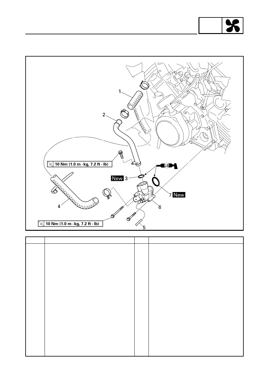
WATER PUMP

WATER PUMP

Order

Job name/Part name

Q’ty

Remarks

Removing the water pump

Remove the parts in the order below.

Seat, fuel tank side panel (left) and 
engine side cover

Refer to “SEAT AND SIDE PANELS” in 
CHAPTER 3.

Left footrest board

Refer to “FOOTREST BOARDS” in 
CHAPTER 3.

Coolant Drain.

Refer to “CHANGING THE COOLANT” in 
CHAPTER 3.

1

Water pump outlet hose

1

2

Water pump outlet pipe

1

3

O-ring

1

4

Radiator outlet hose

1

5

Water pump breather hose

1

6

Water pump assembly

1

7

O-ring

1

For installation, reverse the removal 
procedure.

5 - 8

COOL

WATER PUMP

Order

Job name/Part name

Q’ty

Remarks

Disassembling the water pump

Remove the parts in the order below.

1

Water pump housing cover

1

2

Gasket

1

3

Circlip

1

4

Impeller

1

5

Rubber damper holder

1

6

Rubber damper

1

7

Water pump seal

1

8

Oil seal

1

9

Bearing

1

0

Water pump housing

1

For assembly, reverse the disassembly 
procedure.

5 - 9

COOL

WATER PUMP

DISASSEMBLING THE WATER PUMP

1.Remove:

Rubber damper holder 

1


Rubber damper 

2


(from the impeller, with a thin, flathead
screwdriver)

NOTE:

Do not scratch the impeller shaft.

2.Remove:

Water pump seal 

1


NOTE:

Tap out the water pump seal from the inside of
the water pump housing.

2

Water pump housing

3.Remove:

Oil seal 

1


Bearing 

2


NOTE:

Tap out the bearing and oil seal from the
outside of the water pump housing.

3

Water pump housing

CHECKING THE WATER PUMP

1.Check:

Water pump housing cover 

1


Water pump housing 

2


Impeller 

3


Rubber damper 

4


Rubber damper holder 

5


Cracks/damage/wear 

 Replace.

2.Check:

Water pump outlet pipe
Cracks/damage/wear 

 Replace.

5 - 10

COOL

WATER PUMP

3.Measure:

Impeller shaft tilt
Out of specification 

 Replace.

1

Straightedge

2

Impeller

Max. impeller shaft tilt:

0.15 mm (0.006 in)

ASSEMBLING THE WATER PUMP

1.Install:

Oil seal 

1


(into the water pump housing 

2

)

NOTE:

Install the oil seal with a socket 

3

 that

matches its outside diameter.

New

2.Install:

Water pump seal 

1


(into the water pump housing 

2

)

NOTE:

Before installing the water pump seal 

1

, apply

tap water or coolant onto its outer surface.

CAUTION:

Never lubricate the water pump seal
surface with oil or grease.

NOTE:

Install the water pump seal with the special
tools.

È

Push down.

Mechanical seal installer 

3

P/N. YM-33221, 90890-04078

Middle driven shaft bearing driver

4

:

P/N. YM-04058-1, 90890-04058

New

5 - 11

COOL

WATER PUMP

3.Install:

Rubber damper 

1


Rubber damper holder 

2


NOTE:

Before installing the rubber damper, apply tap
water or coolant onto its outer surface.

CAUTION:

Make sure that the rubber damper and
rubber damper holder are flush with the
impeller.

New

New

CARB

6

CARB

CHAPTER 6.

CARBURETION

CARBURETOR 

............................................................................................. 6-1

CHECKING THE CARBURETOR  ......................................................... 6-4
ASSEMBLING THE CARBURETOR ..................................................... 6-6
ADJUSTING THE FUEL LEVEL  ........................................................... 6-7

CARB

6 - 1

CARB

CARBURETOR

CARBURETION

CARBURETOR

Order

Job name/Part name

Q’ty

Remarks

Removing the carburetor

Remove the parts in the order below.

Seat/fuel tank side panels/fuel tank/
rubber cover

Refer to “SEAT, CARRIERS, FENDERS 
AND FUEL TANK” in CHAPTER 3.

1

Drain hose

1

2

Starter cable/starter plunger

1/1

3

Vacuum chamber breather hose

1

4

Carburetor assembly

1

5

Throttle valve cover

1

6

Throttle cable end

1

7

Throttle cable

2

NOTE:

After removing the carburetor assembly,
remove the throttle cable.

For installation, reverse the removal 
procedure.

6 - 2

CARB

CARBURETOR

Order

Job name/Part name

Q’ty

Remarks

Disassembling the carburetor

Remove the parts in the order below.

1


Float chamber air vent hose

1

2


Throttle stop screw

1

3


Vacuum chamber cover

1

4

 Spring

1

5


Jet needle holder

1

6

 Spring

1

7


Jet needle set

1

8

 Piston 

valve

1

9

 Coasting 

enricher

1

0

 Float 

chamber

1

A

 Drain 

screw 

1

B

 Float

1

Refer 

to 

“ASSEMBLING THE 

CARBURETOR”.

C


Needle valve set

1

6 - 3

CARB

CARBURETOR

Order

Job name/Part name

Q’ty

Remarks

D

 Pilot 

jet

1

E


Pilot screw set

1

Refer to “DISASSEMBLING/
ASSEMBLING THE CARBURETOR”.

F

 Main 

jet

1

G

 Needle 

jet

1

H

 Starter 

jet

1

I

 Pilot 

air 

jet

1

For assembly, reverse the disassembly 
procedure.

6 - 4

CARB

CARBURETOR

CHECKING THE CARBURETOR

1.Check:

Carburetor body

Float chamber
Cracks/damage 

 Replace.

Fuel passage
Contamination 

 Clean as indicated.

Carburetor body 
Contamination 

 Clean.

*****************************************************

Cleaning steps:

Wash the carburetor in a petroleum based
solvent.
(Do not use any caustic carburetor cleaning
solution.)

Blow out all of the passages and jets with
compressed air.

*****************************************************

2.Check:

Float 

1


Float tang 

2


Damage 

 Replace.

3.Check:

Valve seat 

1


Needle valve 

2


O-ring 

3


Contamination/wear/damage 

 Replace as

a set.

NOTE:

Always replace the needle valve and valve
seat as a set.

4.Check:

Piston valve 

1


Scratches/wear/damage 

 Replace.

Rubber diaphragm 

2


Tears 

 Replace.

6 - 5

CARB

CARBURETOR

5.Check:

Vacuum chamber cover 

1


Spring 

2


Cracks/damage 

 Replace.

6.Check:

Diaphragm (coasting enricher) 

1


Spring 

2


Cover 

3


Tears (diaphragm) /damage 

 Replace. 

7.Check:

Jet needle 

1


Main jet 

2


Needle jet 

3


Pilot air jet 

4


Pilot jet 

5


Pilot screw 

6


Starter jet 

7


Starter plunger 

8


Bends/wear/damage 

 Replace.

Blockage 

 Blow out the jets with 

compressed air.

8.Check:

Free movement (piston valve)
Sticks 

 Replace the piston valve guide and

the piston valve.
Insert the piston valve into the carburetor
body, and check for free movement.

9.Check:

Free movement (throttle valve)
Sticks 

 Replace.

6 - 6

CARB

CARBURETOR

ASSEMBLING THE CARBURETOR

CAUTION:

Before reassembling, wash all of the parts
in a clean petroleum based solvent.

1.Install:

Pilot screw 

1


Pilot screw setting:

2-1/2

2.Measure:

Float height 

a


Out of specification 

 Adjust.

*****************************************************

Measurement and adjustment steps:

Hold the carburetor in an upside down
position.

Measure the distance from the mating
surface of the float chamber (gasket
removed) to the top of the float.

NOTE:

The float arm should be resting on the needle
valve, but not compressing it.

If the float height is not within the
specification, check the valve seat and
needle valve.

If either is worn, replace them both.

If both are fine, adjust the float height by
bending the float tang 

1

 on the float.

Recheck the float height.

*****************************************************

Float height (F.H.):

13 mm (0.51 in)

6 - 7

CARB

CARBURETOR

ADJUSTING THE FUEL LEVEL

1.Measure:

Fuel level 

a


Out of specification 

 Adjust. 

*****************************************************

Measurement and adjustment steps:

Place the machine on a level surface.

Connect the fuel level gauge 

1

 to the drain

pipe 

2

Loosen the drain screw 

3

.

Hold the gauge vertically next to the float
chamber line.

Measure the fuel level 

a

 with the gauge.

If the fuel level is incorrect, adjust the fuel
level.

Remove the carburetor.

Check the valve seat and needle valve.

If either is worn, replace them both.

If both are fine, adjust the float level by
bending the float tang 

4

 slightly.

Install the carburetor.

Recheck the fuel level.

*****************************************************

Fuel level:

4.0 ~ 5.0 mm (0.16 ~ 0.20 in)
Above the float chamber mating
surface

Fuel level gauge:

P/N. YM-01312-A, 90890-01312


Content      ..     13      14      15      16     ..