ATV Honda TRX350 TM/TE, TRX350 FM/FE. Service Manual - part 73
 

  Index      Manuals     ATV Honda TRX350 TM/TE, TRX350 FM/FE. Service Manual


Search            copyright infringement  


Content      ..     71      72      73      74     ..


ATV Honda TRX350 TM/TE, TRX350 FM/FE. Service Manual - part 73


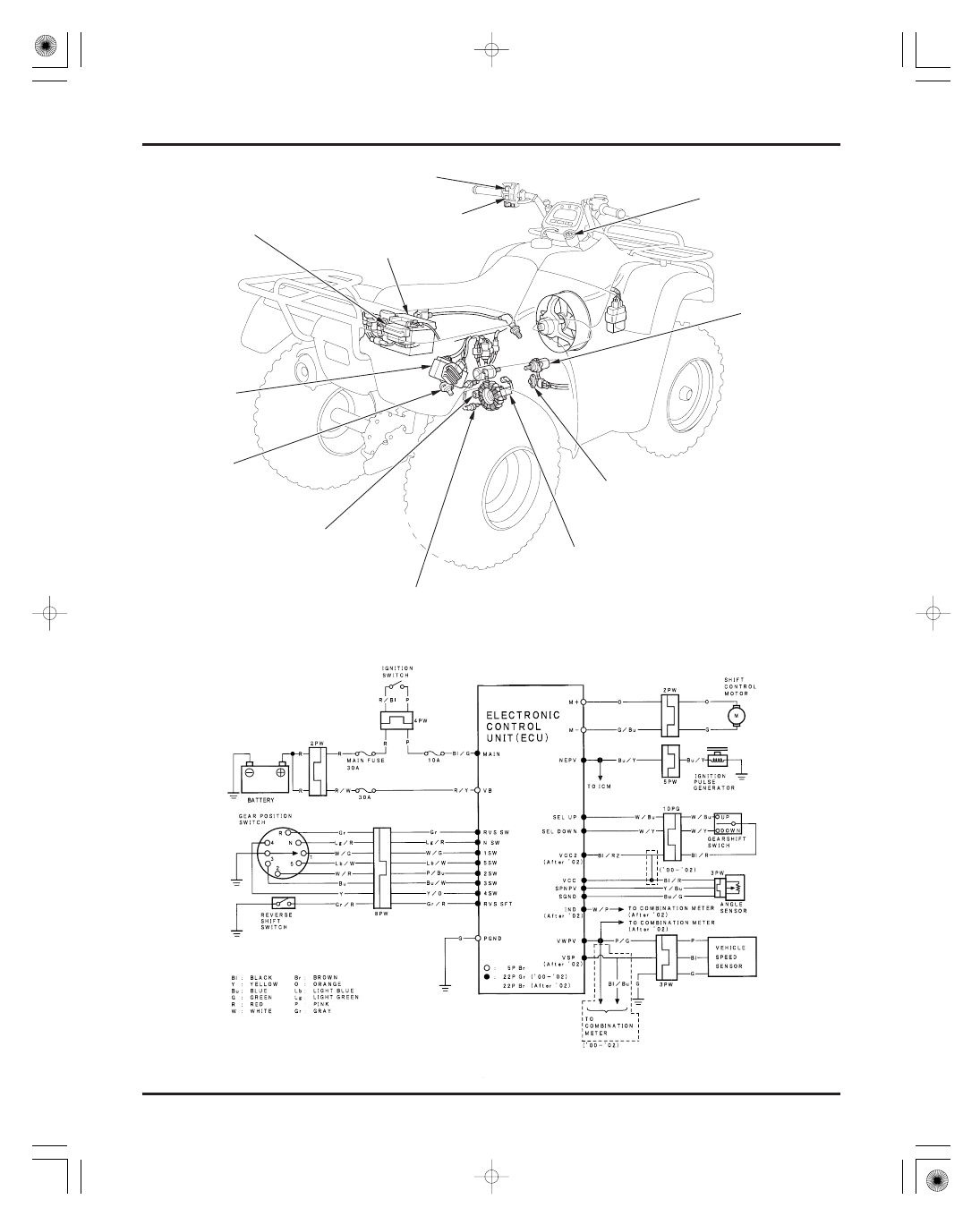
ELECTRIC SHIFT PROGRAM (ESP: TE/FE model)

21-0

FUSE BOX

BATTERY

ANGLE SENSOR

IGNITION SWITCH

SHIFT CONTROL
MOTOR

IGNITION PULSE GENERATOR

REVERSE SHIFT SWITCH

GEAR POSITION SWITCH

ELECTRONIC
CONTROL UNIT

UPSHIFT SWITCH

DOWNSHIFT SWITCH

VEHICLE SPEED
SENSOR

03/01/08 15:59:09 61HN400N_001

-------------------------------------------------------------------------------------------------------------------------------------------------------------

CONTROL MOTOR AND
REDUCTION GEARS

21-22

GEARSHIFT SWITCH

21-24

REVERSE SHIFT SWITCH

21-25

SERVICE INFORMATION

21-1

TROUBLESHOOTING (’00

’02)

21-2

(After ’02)

21-8

ANGLE SENSOR

21-20

GENERAL

TORQUE VALUES

SERVICE INFORMATION

21

21-1

21. ELECTRIC SHIFT PROGRAM (ESP: TE/FE models)

When checking the Electric Shift Program (ESP) system, always follow the steps in the troubleshooting flow chart (page
21-3).
The ESP parts can be serviced with the engine installed in the frame.
The ECU may be damaged if dropped. Also, if the connector is disconnected when current is flowing, the excessive
voltage may damage the ECU. Always turn off the ignition switch before disconnecting or connecting the connectors.
Use a digital tester for ESP system inspection.
For vehicle speed sensor and gear position switch inspection, see section 20.

Angle sensor bolt
Reverse shift switch

6 N·m (0.6 kgf·m , 4.3 lbf·ft)

Apply locking agent to the threads

13 N·m (1.3 kgf·m , 9 lbf·ft)

03/01/08 15:59:17 61HN400N_002

-------------------------------------------------------------------------------------------------------------------------------------------------------------


TROUBLESHOOTING FEATURE

BEFORE TROUBLESHOOTING

ELECTRIC SHIFT PROGRAM (ESP: TE/FE models)

Procedure for ‘‘Fail’’ recurrence

TROUBLESHOOTING (’00

’02)

21-2

When the operator detects the abnormality, check the following before proceeding with the diagnosis:

Attempt to recreate the ‘‘Fail’’ situation from information from the operator and record the vehicle speed, engine revolution
and shift position. Proceed with the diagnosis from this information.

Make sure the battery is fully charged and in good condition.
Make sure the clutch is adjusted properly.
Ask the operator about the following.

How often did the abnormality occur.
Vehicle speed, road situation (level, climbing and etc.), engine revolution
Mileage
Clutch maintenance history

The gear position indicator can indicate ‘‘

’’ when the engine is stopped.

When the engine is running, the indicator may indicate ‘‘

’’ under very limited conditions. This is just a temporary

symptom and occurs when shifting the transmission while the engine speed is high. When this occurs, throttle-back to
decrease engine speed and then shift the transmission. The proper gear position will then appear on the display (it will
replace the ‘‘

’’). Be aware that this is not a problem, and in fact seldom occurs.

When the ECU detects a system abnormality, it has a built-in self-diagnostic function that stops the Electronic Shift (ES)
activity or resets the system entirely (just as when the ignition switch is turned from ‘‘OFF’’ to ‘‘ON’’). The ECU does not have
the capability to inform the operator of the cause of the abnormality, except that the ES function stops immediately when the
ECU detects a failure condition.

When the ECU is in ‘‘failure’’ mode, the shift function is immediately deactivated and will remain so until the ignition switch
is turned to ‘‘OFF’’. When the ignition switch is turned back to ‘‘ON’’, the ECU will be reactived unless it immediately detects
another fail condition. If the ECU does not immediately detect a fail condition, the operator can then document the conditions
that lead to another ‘‘failure’’ mode.

1.
2.
3.
4.

03/01/08 15:59:26 61HN400N_003

-------------------------------------------------------------------------------------------------------------------------------------------------------------


FLOWCHARTS

ELECTRIC SHIFT PROGRAM (ESP: TE/FE models)

Electric shift does not operate

21-3

Shift the gear manually using the gear change
tool.

Faulty transmission or gearshift linkage
(section 9 and 11)

Open circuit in Black/green wire
Loose or poor contact of related terminal

Open circuit in Red/yellow wire
Loose or poor contact of related terminal

Open circuit in Green wire
Loose or poor contact of related terminal

Check for continuity between the Green terminal
of the control unit 5P connector and ground.
There should be continuity.

Turn the ignition switch to ‘‘OFF’’ unless otherwise specified.
Inspect the following before diagnosing the system

Make sure the battery is fully charged and in good condition
Make sure the clutch is adjusted properly.
Check for a blown fuse

Disconnect the control unit 22P (gray) connector
and measure the voltage between the Black/
green (

) terminal of the harness side connector

and ground (

) with the ignition switch turned to

‘‘ON’’.
There should be 11 V minimum.

Disconnect the control unit 5P (brown) connector
and measure the voltage between the Red/yellow
(

) terminal of the harness side connector and

ground (

) with the ignition switch turned to

‘‘ON’’.
There should be 11 V minimum.

When the ECU is found to be faulty, recheck the connectors before replacing it.

Normal

Normal

Normal

Continuity

(Go to following page)

22P CONNECTOR

No voltage

Abnormal

No voltage

No continuity

5P CONNECTOR

ECU

03/01/08 15:59:38 61HN400N_004

-------------------------------------------------------------------------------------------------------------------------------------------------------------


21-4

ELECTRIC SHIFT PROGRAM (ESP: TE/FE models)

Faulty angle sensor

Open or short circuit in
related wire
Loose or poor contact of
related terminal

Replace damaged parts:

Faulty gearshift switch

Open or short circuit in
related wire
Loose or poor contact of
related terminal

Disconnect the angle sensor 3P (white) con-
nector and perform the same inspections at
the angle sensor terminals.

Disconnect the 10P (green) connector and
perform the same inspection at the switch
side 10P connector terminals.

Measure the resistance of the angle sensor at the
control unit 22P connector (page 21-20).

Remove the angle sensor (page 21-21).
Visually inspect the sensor shaft hole and
gearshift spindle for wear or damage.

Measure the resistance of the angle sensor by
removing it from the engine (page 21-20).

Connect the control unit connectors.
Measure the input voltage of the angle sensor at
the sensor 3P connector (page 21-21).

Check for continuity of the gearshift switch at the
control unit 22P (gray) connector (page 21-24).

angle sensor (page 21-21)
gearshift spindle (section 11)

Faulty angle sensor

Open or short circuit in related wire
Loose or poor contact of related terminal
Faulty ECU

Out of range

Normal

Abnormal

Normal

Normal

Normal

Normal

Abnormal

Abnormal

Abnormal

Normal

Abnormal

Normal

Out of range

(From previous page: Continuity)

(Go to following page)

03/01/08 15:59:50 61HN400N_005

-------------------------------------------------------------------------------------------------------------------------------------------------------------

21-5

ELECTRIC SHIFT PROGRAM (ESP: TE/FE models)

Check for continuity of the gear position switch at
the 8P (white) connector (page 20-7).

Check for continuity between the 8P connector
and control unit 22P connector terminals in the
same harness colors of the gear position switch.

Faulty control motor

Disconnect the control motor 2P (white) connec-
tor.
Check for continuity between the 2P connector
and control unit 5P connector terminals in the
same harness colors.

Measure the input voltage of the gearshift switch
at the 10P connector (page 21-24).

Remove the control motor (page 21-22).
Connect a fully charged battery to the control
motor 2P connector terminals.

Open or short circuit in related wire
Loose or poor contact of related terminal
Faulty ECU

Faulty gear position switch

Open circuit in related wire
Loose or poor contact of related terminal

Open circuit in Orange or Green/blue wire
Loose or poor contact of related terminal

Faulty ECU

Normal

Abnormal

Normal

Continuity

Continuity

Motor turns

Abnormal

No continuity

No continuity

CONTROL MOTOR 2P CONNECTOR

(From previous page: Normal)

Does not turn

03/01/08 15:59:59 61HN400N_006

-------------------------------------------------------------------------------------------------------------------------------------------------------------

Electric shift malfunction during vehicle operation

21-6

ELECTRIC SHIFT PROGRAM (ESP: TE/FE models)

Perform the previous troubleshooting ‘‘Electric
shift does not operate’’ (page 21-3).

Check the clutch operation.

Disconnect the control unit 22P (gray) and alterna-
tor/ignition pulse generator 5P (white) connec-
tors.
Check for continuity between their connector ter-
minals in the Blue/yellow wire.

Inspect the clutch (section 9)

Open circuit in Blue/yellow wire
Loose or poor contact of related terminal

Open circuit in Pink/green wire
Loose or poor contact of related terminal

Check that the speedometer functions properly and the engine operates normally before troubleshooting.
If the speedometer does not function properly, perform the meter and vehicle speed sensor inspection (see section 20).

Disconnect the vehicle speed sensor 3P (white)
connector.
Check for continuity between the 3P connector
and control unit 22P connector terminals in the
Pink/green wire.

Faulty ECU

Normal

Normal

Continuity

Continuity

Slipped

No continuity

No continuity

ALTERNATOR/IGNITION PULSE
GENERATOR 5P CONNECTOR

22P CONNECTOR

ECU

VEHICLE SPEED SENSOR 3P CONNECTOR

03/01/08 16:00:08 61HN400N_007

-------------------------------------------------------------------------------------------------------------------------------------------------------------

Electric shift does not operate when engaging the reverse gear

Control motor turns when the shift switch is pushed down from the neutral position with the reverse selector not engaged

21-7

ELECTRIC SHIFT PROGRAM (ESP: TE/FE models)

Shift the gear manually using the gear change
tool.

Disconnect the control unit 22P (gray) connector.
Check for continuity between the 8P connector
and 22P connector terminals in the Gray/red wire.

Faulty transmission or gearshift linkage
(section 9 and 11)

Faulty reverse shift switch

Open circuit in Gray/red wire
Loose or poor contact of related terminal

Faulty reverse shift switch

Short circuit in Gray/red wire

Disconnect the control unit 22P (gray) connector.
Check for continuity between the Gray/red termi-
nal of the 8P connector or 22P connector and
ground.

Check for continuity of the reverse shift switch at
the 8P (white) connector (page 21-25).

Check for continuity of the reverse shift switch at
the 8P (white) connector (page 21-25).

Faulty ECU

Faulty ECU

Normal

Abnormal

Continuity

Abnormal

No continuity

Normal

22P CONNECTOR

8P CONNECTOR

Normal

No continuity

Abnormal

Continuity

22P CONNECTOR

8P CONNECTOR

ECU

ECU

03/01/08 16:00:22 61HN400N_008

-------------------------------------------------------------------------------------------------------------------------------------------------------------

TROUBLESHOOTING (After ’02)

BEFORE TROUBLESHOOTING

TROUBLESHOOTING PROCEDURE

ELECTRIC SHIFT PROGRAM (ESP)

21-8

When the operator detects an abnormality, check the following before proceeding with the diagnosis:

Check the battery voltage (minimum spec. 12.4 V) and any blown fuses.
Turn the ignition switch to ‘‘ON’’ . If the gear indicator blinks, record the number of blinks, since this indicates the type of
failure. Then troubleshoot the indicated failure. Refer to the appropriate problem code within this chapter.

If no ES system failure occurs (the indicator does not blink), perform the following:

Make sure the gear position indicator blinked codes to the user. Check the problem code as described below.

Turn the ignition switch to ‘‘OFF’’
Place the transmission in neutral.
Apply the parking brake so the vehicle does not move.
Push both Upshift switch and Downshift switch to ‘‘ON’’.

When the Electric Control Unit (ECU) detects a system abnormality, it has a built-in self-diagnostic function that stops the
Electric Shift (ES) system or resets the systems entirely (just as when the ignition switch is turned from ‘‘OFF’’ to ‘‘ON’’). If
the ECU detects an ES system failure, the ECU stops the ES system function and records a problem code. The ES system will
not operate, even after the ignition switch is turned to ‘‘OFF’’.

To reset the ES system, turn the ignition switch from ‘‘ON’’ to ‘‘OFF’’ and back to ‘‘ON’’ again. However, if the ECU still
detects a problem, it will continue to deactivate the ES system function. When this occurs, the gear position indicator will
blink a certain number of times to indicate the appropriate problem code.

The ECU is able to record system failures and outputs these as problem codes that are shown on the indicator (i. e., the ‘‘N’’
blinks a designated number of times).

While pushing both switches, turn the ignition switch to ‘‘ON’’.
Before the letter ‘‘N’’ appears on the gear position indicator (in about 2 seconds), release both the shift switches, then
push them again for more than 3 seconds.
If the switches are not released and pushed within 2 seconds, the code number will not appear.

1.
2.

1.

a)
b)
c)
d)

e)

IGNITION SWITCH

UPSHIFT SWITCH

DOWNSHIFT SWITCH

OLD PROBLEM CODE

LATEST PROBLEM CODE

ONE BLINK

ONE BLINK

1 sec

1/4 sec

1/4 sec

1 sec

2 sec

03/01/08 16:00:34 61HN400N_009

-------------------------------------------------------------------------------------------------------------------------------------------------------------

Diagnosis table

ELECTRIC SHIFT PROGRAM (ESP)

21-9

Gear indicator
blinks

Check part and system

Refer to
page

Probable faulty part

If the code number could not be checked (the indicator did not blink), repeat steps 2 and 4.
If a failure is still not indicated (i. e., the ‘‘N’’ does not blink), the problem is as follows:

Electric shift does not operate (page 21-10) and/or
Faulty gear indicator (e. g., does not indicate the problem, keeps indicating the same gear position, indicates a different
gear position than what the transmission is in)

After performing the above troubleshooting steps and repairing the problem, delete the codes as follows:

Turn the ignition switch to ‘‘OFF’’.
Place the transmission in neutral.
Apply the parking brake so the vehicle does not move.
Push both the Upshift and Downshift switches to ‘‘ON’’.
While pushing them, turn the ignition switch to ‘‘ON’’.
Before the letter ‘‘N’’ appears on the shift position indicator (in about 2 seconds), release both the shift switches, then
push them again more than 3 seconds.
If the switches are not released and pushed within 2 seconds, the code number will not appear.
While the indicator is showing the problem code (i. e., blinking with the transmission in neutral), push both electric shift
switches to delete the problem code number.
Turn the ignition switch to ‘‘OFF’’.

No problem

ECU (writing and recording circuit)
ES shift switch system (up and down)
Angle sensor system

Gear position switch system

ECU motor driver circuit
ECU fail-safe relay circuit
ECU voltage convert circuit
Angle sensor system

Angle sensor system

Ignition pulse generator system

Vehicle speed sensor system (vehicle
speed)
Gear position switch system

No problem

ECU

Shift switch or related wire harness or ECU
Angle sensor (abnormally installed) or
related wire harness or ECU
Gear position switch or related wire harness
or ECU

ECU
ECU
ECU

Angle sensor or control motor or related
wire harness or ECU
Angle sensor (short or open) or related wire
harness or ECU
Ignition pulse generator or related wire
harness
Vehicle speed sensor or related wire harness
or ECU
Gear position switch or related wire harness
or ECU

0
1
2
3

4

5
6
7
8

9

10

11

12

21-12
21-12
21-13

21-15

21-16
21-17
21-17
21-13

21-13

21-18

21-19

21-15

2.
3.

4.

a)
b)

a)
b)
c)
d)
e)

f)

g)

03/01/08 16:00:44 61HN400N_010

-------------------------------------------------------------------------------------------------------------------------------------------------------------

+ −

+ −

+ −

+ −

+ −

+ −

+ −

+ −

+ −

+ −

+ −

+ −

+ −

+ −


GEAR INDICATOR PROBLEM

CONNECTIONS:

Light green/Red (

)

Body Ground (

),

when shifting to neutral
White/Green (

)

Body Ground (

),

when shifting to 1st gear
White/Red (

)

Body Ground (

),

when shifting to 2nd gear
Blue (

)

Body Ground (

),

when shifting to 3rd gear
Yellow (

)

Body Ground (

),

when shifting to 4th gear
Light Blue/White (

)

Body Ground (

),

when shifting to 5th gear
Gray (

)

Body Ground (

),

when shifting to reverse

STANDARD: Continuity

CONNECTIONS:

Light green/Red (

)

Body Ground (

),

when shifting to neutral
White/Green (

)

Body Ground (

),

when shifting to 1st gear
Pink/Blue (

)

Body Ground (

),

when shifting to 2nd gear
Blue/White (

)

Body Ground (

),

when shifting to 3rd gear
Yellow/Orange (

)

Body Ground (

),

when shifting to 4th gear
Light Blue/White (

)

Body Ground (

),

when shifting to 5th gear
Gray (

)

Body Ground (

),

when shifting to reverse

STANDARD: Continuity

ELECTRIC SHIFT DOES NOT OPETRATE

ELECTRIC SHIFT PROGRAM (ESP)

21-10

Check the gear indictor.

No indication of gear position
Keeps indicating same gear position
Different gear is indicated

Make sure the ECU, combination meter, gear
position switch and ground wires are properly
connected.

Faulty gear position switch

Loose or poor contact of related circuit
Open circuit of related circuit

Disconnect the gear position switch
connector (8P). Check for continuity at the
gear position switch connector as following:

Turn the ignition switch ‘‘OFF’’.
Shift the gear manually using the gear change
tool.

Faulty transmission or gearshift linkage
(section 9/11)

Troubleshoot the gear position switch system
(page 21-15)

Troubleshoot the ES sift switch system
(page 21-12)

Loose or poor contact of related circuit.

Inspect the following before diagnosing the system.

Make sure the battery is fully charged and in good condition.
Make sure the clutch is adjusted properly.
Blown main (30 A), motor (30 A) or sub fuse, ignition (10 A)

Disconnect the ECU connector (22P/Brown).
Turn the ignition switch to ‘‘OFF’’. Check for
continuity at the ECU connector of the wire
harness side as follows:

Abnormal

Abnormal

GEAR CHANGE TOOL

Normal

Normal

Abnormal

Normal

Normal

Normal

Abnormal

Abnormal

03/01/08 16:00:55 61HN400N_011

-------------------------------------------------------------------------------------------------------------------------------------------------------------

+ −

+ −

+ −

CONNECTION: White/Pink (

)

White/Pink

(

)

STANDARD: Continuity

CONNECTION: White/Pink (

)

Body ground

(

)

STANDARD: No continuity

CONNECTION: White/Pink (

)

Body ground

(

)

STANDARD: No continuity

21-11

ELECTRIC SHIFT PROGRAM (ESP)

Disconnect the combination meter connector
(14P).
Check for continuity of the White/Pink wire
between the ECU connector and the combination
meter connector terminals.

Connect the ECU connector.
Check for continuity between the White/Pink wire
of the combination meter terminal and body
ground with the ignition switch turned to ‘‘ON’’.

Open circuit in White/Pink wire
Loose or poor contact of related circuit

Inspect combination meter (page 20-9).

Faulty combination meter

Replace the ECU with a new one and
troubleshoot again

Check for continuity of the White/Pink wire at the
combination meter connector and body ground.

Abnormal

Normal

Normal

Normal

Abnormal

Abnormal

Normal

03/01/08 16:01:05 61HN400N_012

-------------------------------------------------------------------------------------------------------------------------------------------------------------

+ −

+ −

+ −

+ −

Problem Code 1: ECU (writing and recording circuit)

Problem Code 2: ES Shift Switch System (Up And Down)

ELECTRIC SHIFT PROGRAM (ESP)

CONNECTION:
Shift up switch: Black/Red (

)

White/Blue

(

)

Shift down switch: Black/Red (

)

White/

Yellow (

)

STANDARD: Continuity

CONNECTION:
Shift up switch: Black/Red (

)

White/

Blue (

)

Shift down switch: Black/Red (

)

White/

Yellow (

)

STANDARD: Continuity

21-12

Check the connections of the ECU, gear shift
switch and related circuit.

Replace the ECU with a new one and
troubleshoot again

No problem (temporary failure)

Loose or poor connections in related circuit.

Delete the problem code number.
Check the ES system failure (the gear indicator
blinks) when turning the ignition switch from
‘‘OFF’’ to ‘‘ON’’.

Check for mud or water in the left handlebar
switch housing.

Clean the left handlebar
switch housing

Replace the left
handlebar switch

Loose or poor contact of
related circuit
Open or short of related
circuit

Replace the ECU with a new one and
troubleshoot again

No problem (temporary failure)

Check the ES system failure (the gear indicator
blinks) when turning the ignition switch from
‘‘OFF’’ to ‘‘ON’’.

Disconnect the left handlebar switch
connector.
Check for continuity while pushing the shift
switches up or down.

Disconnect the ECU connector (22P/Brown).
Check for continuity at the wire harness side
connector while pushing the shift switches up or
down.

Abnormal

Normal

Normal

Abnormal

Normal

Abnormal

Normal

Abnormal

Blinks

No blinks

Blinks

No blinks

03/01/08 16:01:18 61HN400N_013

-------------------------------------------------------------------------------------------------------------------------------------------------------------

+ −

+ −

+ −

+ −

Problem Code 3, 8, 9: Angle Sensor System

ELECTRIC SHIFT PROGRAM (ESP)

CONNECTION: Black/Red (

)

Blue/Green (

)

STANDARD: 4 k

6 k

CONNECTION:
Black/Red (

)

Black/Red (

)

Blue/Green (

)

Blue Green (

)

CONNECTION: Yellow/Blue (

)

Yellow/Blue

(

)

STANDARD: Continuity

21-13

Check the connections of the ECU, angle sensor
and related circuit.

Loose or poor contact of related circuit

Make sure the angle sensor is correctly installed
to the engine.

Open or short of related
circuit

Faulty angle sensor

Loosen the angle sensor mounting bolts.

Open circuit in Yellow/Blue wire

Disconnect the angle sensor connector (3P).
Check for continuity for the ECU and angle
sensor connectors.

Disconnect the angle sensor connector (3P).
Check for continuity of the Yellow/Blue wire
between the ECU connector and the angle sensor
connector.

Turn the ignition switch to ‘‘OFF’’.
Disconnect the ECU connector (22P/Brown).
Measure the resistance between the Black/Red
and Blue/Green terminals of the wire harness
side.

Normal

Abnormal

Abnormal

Abnormal

Normal

Abnormal

Normal

Normal

Normal

Abnormal

ANGLE SENSOR
CONNECTOR

ANGLE SENSOR
CONNECTOR

03/01/08 16:01:30 61HN400N_014

-------------------------------------------------------------------------------------------------------------------------------------------------------------

+ −

+ −

07YMZ

0010100

TOOL:
ECU test harness, 22P

CONNECTION: Black/Red (

)

Blue/Green (

)

STANDARD: 4.75

5.25 V

CONNECTION: Yellow/Blue (

)

Blue/Green

(

)

STANDARD: 0

5 k

21-14

ELECTRIC SHIFT PROGRAM (ESP)

Check the ES system failure (the gear indicator
blinks) when turning the ignition switch from
‘‘OFF’’ to ‘‘ON’’.

Replace the ECU with a new one and
troubleshoot again

Faulty angle sensor

Replace the ECU with a new one and
troubleshoot again

No problem (temporary failure)

Connect the angle sensor connector (3P).
Connect the ECU test harnesses between the
main wire harness and the ECU.

Turn the ignition switch ‘‘OFF’’.
Disconnect the ECU connector (22P/Brown).
Measure the resistance between the Yellow/Blue
and Blue/Green terminals of the wire harness
side while shifting through all the gears (1st, 2nd,
3rd, 4th, 5th, Reverse)

With the ignition switch turned to ‘‘ON’’, measure
the voltage between the Black/Red and the Blue/
Green terminals.

Normal

Abnormal

Abnormal

Normal

No blinks

Blinks

03/01/08 16:01:39 61HN400N_015

-------------------------------------------------------------------------------------------------------------------------------------------------------------

+ −

+ −

+ −

+ −

+ −

+ −

+ −

+ −

+ −

+ −

+ −

+ −

+ −

+ −

Problem Codes 4 or 12: Gear Position Switch System

ELECTRIC SHIFT PROGRAM (ESP)

CONNECTIONS:

Light green/Red (

)

Body Ground (

),

when shifting to neutral
White/Green (

)

Body Ground (

),

when shifting to 1st gear
White/Red (

)

Body Ground (

),

when shifting to 2nd gear
Blue (

)

Body Ground (

),

when shifting to 3rd gear
Yellow (

)

Body Ground (

),

when shifting to 4th gear
Light Blue/White (

)

Body Ground (

),

when shifting to 5th gear
Gray (

)

Body Ground (

),

when shifting to reverse

STANDARD: Continuity

CONNECTIONS:

Light green/Red (

)

Body Ground (

),

when shifting to neutral
White/Green (

)

Body Ground (

),

when shifting to 1st gear
Pink/Blue (

)

Body Ground (

),

when shifting to 2nd gear
Blue/White (

)

Body Ground (

),

when shifting to 3rd gear
Yellow/Orange (

)

Body Ground (

),

when shifting to 4th gear
Light Blue/White (

)

Body Ground (

),

when shifting to 5th gear
Gray (

)

Body Ground (

),

when shifting to reverse

STANDARD: Continuity

STANDARD: 5 V

21-15

Check the connections of the ECU, gear position
switch and related circuit.

Loose or poor contact of related circuit

Fa ul ty ge ar posi ti on
switch
Open or short circuit in
related circuit

Replace the ECU unit with a new one and
troubleshoot again

Replace the ECU with a new one and
troubleshoot again

No problem (temporary failure)

Check the ES system failure (the gear indicator
blinks) when turning the ignition switch from
‘‘OFF’’ to ‘‘ON’’.

Disconnect the gear position switch
connector (8P). Check for the continuity at
the gear position switch connector as
follows:

Turn the ignition switch to ‘‘OFF’’.
Disconnect the ECU connector (22P/Brown).
Check for continuity at the ECU connector of the
wire harness side as follows:

Connect the ECU connector (22P/Brown).
Disconnect the gear position switch connector
(8P). Turn the ignition switch to ‘‘ON’’.
Measure the voltage at the gear position switch
connector of the wire harness side as same
connections as above procedure.

Normal

Abnormal

Abnormal

Abnormal

Abnormal

Normal

Normal

Normal

Blinks

No blinks

03/01/08 16:01:49 61HN400N_016

-------------------------------------------------------------------------------------------------------------------------------------------------------------


Content      ..     71      72      73      74     ..