Suzuki GSX-R1000. Service Manual - part 34


  Index      Manuals     Suzuki GSX-R1000. Service Manual


Search            copyright infringement  


Content      ..     32      33      34      35     ..


Suzuki GSX-R1000. Service Manual - part 34


5B-2 Manual Transmission: 

Repair Instructions

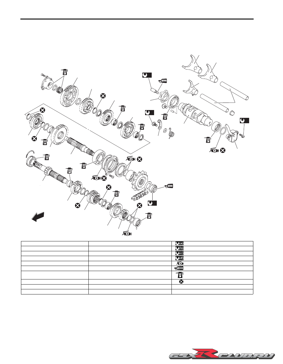
Transmission Components

B947H15206001

1

2

3

5

6

7

8

9

11

10

20

12

13

14

15

16

17

18

19

4

FWD

FWD

(a)

(b)

(c)

(d)

I947H1520072-02

1. 2nd drive gear

11. 5th driven gear

: 145 N

m (14.5 kgf-m, 105.0 lbf-ft)

2. 6th drive gear

12. 1st driven gear

: 10 N

m (1.0 kgf-m, 7.0 lbf-ft)

3. 3rd/4th drive gear

13. Gearshift cam stopper

: 13 N

m (1.3 kgf-m, 9.5 lbf-ft)

4. 5th drive gear

14. Gearshift cam plate

: 6.5 N

m (0.65 kgf-m, 4.7 lbf-ft)

5. Countershaft/1st drive gear

15. Gearshift cam

: Apply grease to the oil seal lip.

6. Driveshaft

16. Gearshift fork shaft

: Apply thread lock to the thread part.

7. 2nd driven gear

17. Gearshift fork (For 3rd/4th drive gear)

: Apply engine oil.

8. 6th driven gear

18. Gearshift fork (For 6th driven gear)

: Do not reuse.

9. 3rd driven gear

19. Gearshift fork (For 5th driven gear)

10. 4th driven gear

20. GP switch

-------------------------------------------------------------------------------------------------------------------------------------------------------------

Manual Transmission:  5B-3

Transmission Removal

B947H15206002

1) Remove the engine assembly from the frame. Refer 

to “Engine Assembly Removal” in Section 1D 
(Page 1D-20).

2) Remove the engine top side. Refer to “Engine Top 

Side Disassembly” in Section 1D (Page 1D-26).

3) Separate the upper and lower crankcases. Refer to 

“Engine Bottom Side Disassembly” in Section 1D 
(Page 1D-49).

Countershaft Assembly

1) Remove the gearshift shaft plug (1) and gearshift 

fork/gearshift shaft (2).

2) Remove the clutch push rod oil seal (3) and 

countershaft assembly (4).

3) Remove the bearing pin (5) and C-ring (6).

Gearshift Fork and Gearshift Cam

1) Remove the gearshift cam bearing retainer screws.

2) Remove the gearshift fork shaft (1).

3) Remove the gearshift cam (2) along with its bearing.

4) Remove the gearshift forks (3).

Driveshaft Assembly

1) Remove the spacer (1).

2) Remove the driveshaft oil seal retainer (2).

3) Remove the driveshaft left bearing case bolts.

1

2

3

4

I947H1520023-01

5

6

I947H1520024-01

1

2

3

I947H1520025-01

1

2

I947H1520026-01

I947H1520027-01

-------------------------------------------------------------------------------------------------------------------------------------------------------------

5B-4 Manual Transmission: 

4) Using suitable size bolts (3), remove the driveshaft 

left bearing case (4).

5) Remove the dowel pin.

6) Remove the driveshaft right bearing case bolts.

7) Using suitable size bolts (5), remove the driveshaft 

right bearing assembly (6).

8) Remove the driveshaft assembly (7).

Bearing and Oil Seal

NOTE

If there is no abnormal condition, the oil seal 
and bearing removal is not necessary.


CAUTION

!


The removed oil seal and bearing must be 
replaced with a new one.


1) Remove the gearshift cam bearing (1) with the 

special tools.

CAUTION

!


Be careful not to lean the bearing remover.


Special tool

(A):  09923–74511 (Bearing remover)
(B):  09930–30104 (Rotor remover sliding 

shaft)

2) Remove the gearshift shaft oil seal (2). (LH only)

3

4

I947H1520028-01

5

6

I947H1520029-01

7

I947H1520030-01

(A)

(B)

1

I947H1520031-02

2

I947H1520032-01

-------------------------------------------------------------------------------------------------------------------------------------------------------------

Manual Transmission:  5B-5

3) Remove the gearshift shaft bearings (3) and (4) with 

the special tool.

Special tool

(C):  09921–20240 (Bearing remover set)

4) Remove the driveshaft left bearing with the special 

tool.

Special tool

(D):  09913–70210 (Bearing installing set (10 

– 75 

Φ

))

5) Remove the driveshaft left bearing oil seal from the 

retainer using the special tool.

Special tool

(D):  09913–70210 (Bearing installing set (10 

– 75 

Φ

))

Transmission Installation

B947H15206003

Install the transmission in the reverse order of removal. 
Pay attention to the following points:

Bearing and Oil Seal

CAUTION

!


Replace the removed bearings and oil seals 
with new ones.


• Install the driveshaft left bearing oil seal into the 

retainer using the special tool.

Special tool

(A):  09913–70210 (Bearing installing set (10 

– 75 

Φ

))

• Install the driveshaft left bearing with the special tool.

NOTE

The stamped mark side of the driveshaft left 
bearing faces outside.


Special tool

(A):  09913–70210 (Bearing installing set (10 

– 75 

Φ

))

4

3

(C)

(C)

I947H1520033-01

(D)

I947H1520034-01

(D)

I947H1520035-01

(A)

I947H1520036-01

(A)

I947H1520037-01

-------------------------------------------------------------------------------------------------------------------------------------------------------------

5B-6 Manual Transmission: 

• Install the gearshift shaft bearings (1) and (2) with the 

special tool.

NOTE

The stamped mark side of the gearshift shaft 
bearing faces outside.


Special tool

(A):  09913–70210 (Bearing installing set (10 

– 75 

Φ

))

• Install the gearshift shaft oil seal (3) with the special 

tool.

Special tool

(A):  09913–70210 (Bearing installing set (10 

– 75 

Φ

))

• Apply grease to the oil seal lip.

:  Grease 99000–25010 (SUZUKI SUPER 

GREASE “A” or equivalent)

• Install the gearshift cam bearing with the special tool.

Special tool

(A):  09913–70210 (Bearing installing set (10 

– 75 

Φ

))

Driveshaft Assembly

• Put the driveshaft assembly (1) into the lower 

crankcase.

• Install the driveshaft right bearing assembly (2).

• Apply thread lock to the bolts and tighten them to the 

specified torque.

:  Thread lock cement 99000–32110 

(THREAD LOCK CEMENT SUPER “1322” or 
equivalent)

Tightening torque
Driveshaft right bearing case bolt (a):  12 N·m (1.2 
kgf-m, 8.7 lbf-ft)

• Install the dowel pin.

1

2

(A)

(A)

I947H1520038-01

(A)

3

I947H1520039-01

(A)

I947H1520040-01

1

2

(a)

I947H1520041-01

-------------------------------------------------------------------------------------------------------------------------------------------------------------

Manual Transmission:  5B-7

• Apply grease to the O-ring and install the driveshaft 

left bearing case (3).

CAUTION

!


Replace the O-ring with a new one.


:  Grease 99000–25010 (SUZUKI SUPER 

GREASE “A” or equivalent)

• Apply thread lock to the bolts and tighten them to the 

specified torque.

:  Thread lock cement 99000–32110 

(THREAD LOCK CEMENT SUPER “1322” or 
equivalent)

Tightening torque
Driveshaft left bearing case bolt (b):  12 N·m (1.2 
kgf-m, 8.7 lbf-ft)

• Apply grease to the oil seal lip and O-ring.

CAUTION

!


Replace the O-ring with a new one.


:  Grease 99000–25010 (SUZUKI SUPER 

GREASE “A” or equivalent)

• Install the oil seal retainer (4).

• Apply thread lock to the screws and tighten them to 

the specified torque.

:  Thread lock cement 99000–32110 

(THREAD LOCK CEMENT SUPER “1322” or 
equivalent)

Tightening torque
Driveshaft oil seal retainer screw (c):  12 N·m (1.2 
kgf-m, 8.7 lbf-ft)

• Apply grease to the O-ring (5) and install it to the 

driveshaft.

CAUTION

!


Replace the O-ring with a new one.


:  Grease 99000–25010 (SUZUKI SUPER 

GREASE “A” or equivalent)

• Install the spacer (6).

Gearshift Cam and Gearshift Fork

• Install the gearshift forks (1) as shown.

3

I947H1520042-01

(b)

(b)

I947H1520043-01

(c)

4

I947H1520044-01

5

6

I947H1520045-02

1

I947H1520046-01

-------------------------------------------------------------------------------------------------------------------------------------------------------------

5B-8 Manual Transmission: 

• Install the gearshift cam (2) with the bearing fitted.

• With engaging each fork end to the cam groove, insert 

the fork shaft (3).

• Apply thread lock to the screws and tighten them to 

the specified torque.

:  Thread lock cement 99000–32110 

(THREAD LOCK CEMENT SUPER “1322” or 
equivalent)

Tightening torque
Gearshift cam bearing retainer screw (a):  10 N·m (
1.0 kgf-m, 7.0 lbf-ft)

Countershaft

• Install the C-ring (1) and bearing pin (2) to the upper 

crankcase.

• Install the countershaft assembly to the upper 

crankcase.

NOTE

Align the C-ring with the groove of bearing 
and the bearing pin with the indent on the 
bearing.


• Turn the bearing and set the bearing dowel pin in 

position.

• Install the clutch push rod oil seal (3).

• Install the gearshift fork/gearshift shaft (4) and 

gearshift shaft plug (5).

2

I947H1520047-01

3

(a)

I947H1520048-01

1

2

I947H1520049-01

I947H1520050-01

I947H1520051-01

3

5

4

I947H1520052-01

-------------------------------------------------------------------------------------------------------------------------------------------------------------

Manual Transmission:  5B-9

Transmission Construction

B947H15206004

1

2

I947H1520060-02

1. Countershaft

2. Driveshaft

-------------------------------------------------------------------------------------------------------------------------------------------------------------

5B-10 Manual Transmission: 

Countershaft Gear / Driveshaft Gear 
Disassembly and Assembly

B947H15206005

Refer to “Transmission Removal” (Page 5B-3) and 
“Transmission Installation” (Page 5B-5).

Disassembly

CAUTION

!


Identify the position of each removed part. 
Organize the parts in their respective groups 
(i.e., drive or driven) so that they can be 
reinstalled in their original positions.


Countershaft

Disassemble the countershaft as shown in the 
transmission construction. Refer to “Transmission 
Construction” (Page 5B-9)
.
Pay attention to the following points:

• Remove the 6th drive gear snap ring (1) from its 

groove and slide it towards the 3rd/4th drive gears (2).

Special tool

:  09900–06104 (Snap ring remover (Open 

type))

• Slide the 6th (3) and 2nd (4) drive gears toward the 

3rd/4th drive gears (2), then remove the 2nd drive 
gear circlip (5).

• Remove the 2nd drive gear (4) and 6th drive gear (3).

• Remove the countershaft bearing (6) using hydraulic 

press.

Driveshaft

• Disassembly the driveshaft as shown in the 

transmission construction. Refer to “Transmission 
Construction” (Page 5B-9)
.

2

1

I947H1520061-02

2

3

5

4

I947H1520062-01

6

I947H1520063-01

-------------------------------------------------------------------------------------------------------------------------------------------------------------

Manual Transmission:  5B-11

Assembly

NOTE

When reassembling the transmission gears, 
attention must be given to the locations and 
positions of washers and snap rings. The 
cross sectional view shows the correct 
position of the gears, bushings, washers and 
snap rings. Refer to “Transmission 
Construction” (Page 5B-9)
.


CAUTION

!


• Never reuse a snap ring. After a snap ring 

has been removed from the shaft, it should 
be discarded and a new snap ring must be 
installed.

• When installing a new snap ring, do not 

expand the end gap larger than required to 
slip the snap ring over the shaft.

• After installing a snap ring, make sure that 

it is completely seated in the groove and 
securely fitted.


NOTE

• Rotate the bearing by hand to inspect if 

there is any abnormal noise and for 
smooth rotation. Replace the bearing if 
there is anything unusual.

• Before installing the gears, apply engine 

oil to the driveshaft and countershaft.

• Before installing the oil seal, apply grease 

to the oil seal lip.


:  Grease 99000–25010 (SUZUKI SUPER 

GREASE “A” or equivalent)

• When installing a new snap ring (1), pay attention to 

its direction. Fit it to the side where the thrust is as 
shown in the figure.

Driveshaft

• When installing the gear bushings onto the driveshaft, 

align the shaft oil holes “A” with the bushing oil hole 
“B”.

Countershaft

• Install the countershaft bearing (1) using a hydraulic 

press and special tool.

Special tool

(A):  09913–70210 (Bearing installing set (10 

– 75 

Φ

))

“A”: Thrust

“B”: Sharp edge

1

“A”

“B”

I649G1520049-02

“A”

“B”

I947H1520064-01

“A”

“B”

I947H1520065-01

1

1

(A)

I947H1520066-02

-------------------------------------------------------------------------------------------------------------------------------------------------------------

5B-12 Manual Transmission: 

• When installing the gear bushing onto the 

countershaft, align the shaft oil hole “A” with the 
bushing oil hole “B”.

Transmission Related Parts Inspection

B947H15206006

Refer to “Transmission Removal” (Page 5B-3)
“Transmission Installation” (Page 5B-5) and 
“Countershaft Gear / Driveshaft Gear Disassembly and 
Assembly” (Page 5B-10).

Gearshift Fork to Groove Clearance

NOTE

The clearance for each gearshift fork plays 
an important role in the smoothness and 
positiveness of the shifting action.


Using the thickness gauge, check the gearshift fork 
clearance in the groove of its gear.
If the clearance checked is noted to exceed the limit 
specified, replace the fork or its gear, or both.

Special tool

(A):  09900–20803 (Thickness gauge)

Gearshift fork to gearshift fork groove clearance
Standard: 0.1 – 0.3 mm (0.004 – 0.012 in)
Service limit: 0.5 mm (0.02 in)

Gearshift Fork Groove Width

Measure the gearshift fork groove width using the 
vernier calipers.

Special tool

(A):  09900–20102 (Vernier calipers (200 mm))

Gearshift fork groove width
Standard: 5.0 – 5.1 mm (0.197 – 0.201 in)

Gearshift Fork Thickness

Measure the gearshift fork thickness using the vernier 
calipers.

Special tool

(A):  09900–20102 (Vernier calipers (200 mm))

Gearshift fork thickness
Standard: 4.8 – 4.9 mm (0.189 – 0.193 in)

“A”

“B”

I947H1520067-01

(A)

I649G1520056-03

(A)

I649G1520057-03

(A)

I649G1520058-03

-------------------------------------------------------------------------------------------------------------------------------------------------------------

Manual Transmission:  5B-13

Gearshift Cam

Inspect the gearshift cam groove for abnormal wear and 
damage. If any defects are found, replace the gearshift 
cam with a new one.

Gearshift Cam Bearing

Inspect the gearshift cam bearings, left and right for 
abnormal noise and smooth rotation.
Replace the bearing if there is anything unusual. Refer 
to “Transmission Removal” (Page 5B-3) and 
“Transmission Installation” (Page 5B-5).

Driveshaft Bearing

Inspect the driveshaft left bearing for abnormal noise 
and smooth rotation while it is in the case.
Replace the bearing if there is anything unusual. Refer 
to “Transmission Removal” (Page 5B-3) and 
“Transmission Installation” (Page 5B-5).

Inspect the driveshaft right bearing for abnormal noise 
and smooth rotation.
If there is anything unusual, replace the bearing 
assembly. Refer to “Transmission Removal” (Page 5B-3) 
and “Transmission Installation” (Page 5B-5).

Driveshaft Oil Seal

Inspect the driveshaft left bearing dust seal for wear and 
damage.
Replace the dust seal if there is anything unusual. Refer 
to “Transmission Removal” (Page 5B-3) and 
“Transmission Installation” (Page 5B-5).

Gear Position (GP) Switch Inspection

B947H15206007

Refer to “Side-stand / Ignition Interlock System Parts 
Inspection” in Section 1I (Page 1I-7)
.

I947H1520053-01

I947H1520054-01

I947H1520056-01

I837H1520041-01

I947H1520057-01

-------------------------------------------------------------------------------------------------------------------------------------------------------------

5B-14 Manual Transmission: 

Gear Position (GP) Switch Removal and 
Installation

B947H15206008

Removal

1) Turn the ignition switch OFF.

2) Lift and support the fuel tank. Refer to “Fuel Tank 

Removal and Installation” in Section 1G (Page 1G-
9).

3) Disconnect the gear position switch lead wire 

coupler (1).

4) Remove the engine sprocket cover. Refer to “Engine 

Sprocket Removal and Installation” in Section 3A 
(Page 3A-2).

5) Remove the GP switch (2).

Installation

Install the gear position switch in the reverse order of 
removal. Pay attention to the following points:

• Apply grease to the O-ring.

CAUTION

!


Replace the O-ring with a new one.


NOTE

Align the gear position switch pin “A” with 
the gearshift cam hole “B”.


:  Grease 99000–25010 (SUZUKI SUPER 

GREASE “A” or equivalent)

• Tighten the gear position switch mounting bolts to the 

specified torque.

Tightening torque
Gear position switch mounting bolt (a):  6.5 N·m (
0.65 kgf-m, 4.5 lbf-ft)

• Route the gear position switch lead wire. Refer to 

“Wiring Harness Routing Diagram” in Section 9A 
(Page 9A-7).

1

I947H1520068-01

2

I947H1520069-01

“A”

“B”

I947H1520070-01

(a)

I947H1520071-01

-------------------------------------------------------------------------------------------------------------------------------------------------------------

Manual Transmission:  5B-15

Gearshift Lever Construction

B947H15206009

Gearshift Lever Removal and Installation

B947H15206010

Removal

Remove the gearshift lever as shown in the gearshift 
lever construction. Refer to “Gearshift Lever 
Construction” (Page 5B-15).

Installation

1) Install the gearshift lever as shown in the gearshift 

lever construction. Refer to “Gearshift Lever 
Construction” (Page 5B-15)
.

2) After installing the gearshift lever, check the gearshift 

lever height. Refer to “Gearshift Lever Height 
Inspection and Adjustment” (Page 5B-16).

“ a ”

1

(a)

(b)

2

3

4

5

“A”

I947H1520058-02

1. Gearshift lever bracket

4. Snap ring

“a”: 65 – 75 mm (2.6 – 3.0 in)

: Apply grease.

2. Gearshift lever shaft

5. Gearshift lever

: 28 N

m (2.8 kgf-m, 20.0 lbf-ft)

: Do not reuse.

3. Washer

“A”: Footrest top surface

: 40 N

m (4.0 kgf-m, 29.0 lbf-ft)

-------------------------------------------------------------------------------------------------------------------------------------------------------------

5B-16 Manual Transmission: 

Gearshift Lever Height Inspection and 
Adjustment

B947H15206011

Inspect and adjust the gearshift lever height in the 
following procedures:

1) Inspect the gearshift lever height “a” between the 

lever top and footrest.
Adjust the gearshift lever height if necessary.

Gearshift lever height “a”
Standard: 65 – 75 mm (2.6 – 3.0 in)

2) Loosen the lock-nuts (1).

3) Turn the gearshift link rod (2) until the gearshift lever 

is 65 – 75 mm (2.6 – 3.0 in) below the top of the 
footrest.

4) Tighten the lock-nuts securely.

Gearshift Shaft / Gearshift Cam Plate Components

B947H15206012

“ a ”

I947H1520001-01

1

2

I947H1520002-01

1

2

3

4

(c)

(a)

(c)

(b)

FWD

FWD

I947H1520073-01

1. Gearshift shaft

: 19 N

m (1.9 kgf-m, 13.5 lbf-ft)

: Apply thread lock to the thread part.

2. Gearshift cam drive plate

: 13 N

m (1.3 kgf-m, 9.5 lbf-ft)

: Apply thread lock to the thread part.

3. Gearshift cam plate

: 8.5 N

m (0.85 kgf-m, 6.0 lbf-ft)

: Apply engine oil to bearing.

4. Gearshift cam stopper

: Apply grease to oil seal lip.

: Do not reuse.

-------------------------------------------------------------------------------------------------------------------------------------------------------------

Manual Transmission:  5B-17

Gearshift Shaft Construction

B947H15206013

Gearshift Shaft / Gearshift Cam Plate Removal 
and Installation

B947H15206014

Removal

1) Remove the engine sprocket cover. Refer to “Engine 

Sprocket Removal and Installation” in Section 3A 
(Page 3A-2).

2) Remove the clutch components. Refer to “Clutch 

Removal” in Section 5C (Page 5C-5).

3) Remove the snap ring (1) and washer (2) from the 

gearshift shaft.

Special tool

:  09900–06107 (Snap ring remover (Open 

type))

4) Remove the gearshift shaft assembly (3).

1

2

3

2

(c)

5

4

(a)

3

6

(b)

(a)

I947H1520059-03

1. Gearshift shaft

6. Gearshift plate return spring

: Apply thread lock to the thread part.

2. Washer

: 8.5 N

m (0.85 kgf-m, 6.0 lbf-ft)

: Apply thread lock to the thread part.

3. Snap ring

: 13 N

m (1.3 kgf-m, 9.5 lbf-ft)

: Apply engine oil to bearing.

4. Gearshift shaft return spring

: 19 N

m (1.9 kgf-m, 13.5 lbf-ft)

: Do not reuse.

5. Gearshift cam drive plate

: Apply grease.

1

2

3

I947H1520003-01

-------------------------------------------------------------------------------------------------------------------------------------------------------------


Content      ..     32      33      34      35     ..