Suzuki GSX-R1000. Service Manual - part 17
 

  Index      Manuals     Suzuki GSX-R1000. Service Manual


Search            copyright infringement  


Content      ..     15      16      17      18     ..


Suzuki GSX-R1000. Service Manual - part 17


1D-28 Engine Mechanical: 

8) Remove the intake camshaft (6) and exhaust 

camshaft (7).

Cylinder Head

NOTE

The cylinder head can not be serviced with 
the engine installed in the frame.


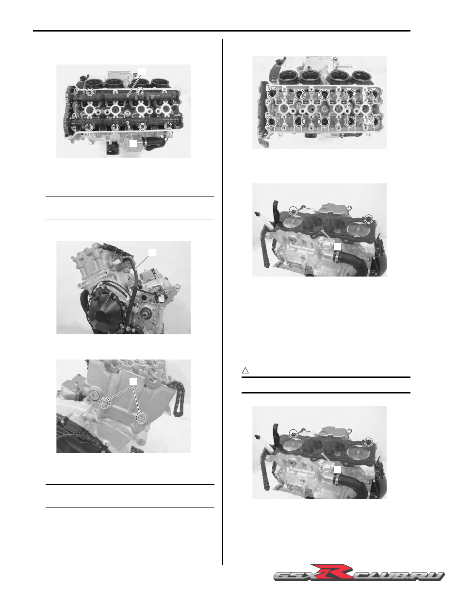
1) Disconnect the water bypass hose (1).

2) Remove the cylinder head bolts (M6) (2).

3) Remove the cylinder head bolts (M10) and washers.

NOTE

When loosening the cylinder head bolts, 
loosen each bolt little by little diagonally.


4) Remove the cylinder head.

5) Remove the dowel pins and cylinder head gasket 

(3).

Engine Top Side Assembly

B947H11406020

Assemble the engine top side in the reverse order of 
disassembly. Pay attention to the following points:

Cylinder Head

• Install the dowel pins and a new cylinder head gasket 

(1) to the cylinder.

CAUTION

!


Use a new gasket to prevent gas leakage.


6

7

I947H1140037-01

1

I947H1140038-01

2

I947H1140039-01

I947H1140040-01

3

I947H1140041-01

1

I947H1140042-01

-------------------------------------------------------------------------------------------------------------------------------------------------------------

Engine Mechanical:  1D-29

• Place the cylinder head on the gasket.

NOTE

• When installing the cylinder head, keep the 

cam chain taut.

• Apply engine oil to the washer and thread 

portion of the cylinder head bolts (M10) 
before tightening them.


• Tighten the cylinder head bolts (M10) to the specified 

torque with a torque wrench sequentially and 
diagonally.

• Additionally tighten the cylinder head bolts with the 

specified angles diagonally using an angular torque 
gauge.

Tightening torque
Cylinder head bolt (M10):  31 N

m (3.1 kgf-m, 22.5 

lbf-ft) then turn in 1/6 (60

°

) turn

• After firmly tightening the cylinder head bolts (M10), 

tighten the cylinder head bolts (M6) (2).

Tightening torque
Cylinder head bolt (M6) (a):  10 N·m (1.0 kgf-m, 7.0 
lbf-ft)

• Connect the water bypass hose (3).

Camshaft

• The camshafts are identified by the embossed letters.

IN: Intake camshaft
EX: Exhaust camshaft

• Before placing the camshafts on the cylinder head, 

apply molybdenum oil to their journals, cam faces and 
holders.

M/O:  Molybdenum oil  (MOLYBDENUM OIL 
SOLUTION)

I823H1140063-01

I947H1140043-01

(a)

2

I947H1140044-01

3

I947H1140045-01

I947H1140046-01

-------------------------------------------------------------------------------------------------------------------------------------------------------------

1D-30 Engine Mechanical: 

• Turn the crankshaft clockwise and align the line “A” on 

the CKP sensor rotor to the slit “B” of cap hole thread 
while keeping the cam chain pulled upward.

CAUTION

!


• Pull the cam chain upward, or the chain 

will be caught between crankcase and cam 
drive sprocket.

• To adjust the camshaft timing correctly, be 

sure to align the line “A” with slit “B” and 
hold this position when installing the 
camshafts.


• Pull the cam chain lightly.

• Turn the exhaust camshaft so that the arrow is aligned 

with the gasket surface of the cylinder head.
(The exhaust camshaft sprocket has an arrow marked 
“1” “C”.)

• Engage the cam chain with the exhaust camshaft 

sprocket.

NOTE

Before installing the camshaft, check that the 
tappets are installed correctly.


• Bind the cam chain and the sprocket with a proper 

clamp (1) to prevent the cam chain disengagement 
while installing the camshaft journal holders.

• The other arrow marked “2” “D” should now be 

pointing straight up. Starting from the roller pin that is 
directly above the arrow marked “2” “D”, count out 14 
roller pins (from the exhaust camshaft side going 
towards the intake camshaft side).

• Engage the 14th roller pin “E” on the cam chain with 

the arrow marked “3” on the intake camshaft sprocket.

• Bind the cam chain and the sprocket with a proper 

clamp (2) to prevent the cam chain disengagement 
while installing the camshaft journal holders.

NOTE

The cam chain should now be on all three 
sprockets. Be careful not to move the 
crankshaft until the camshaft journal holders 
and cam chain tension adjuster are secured.


I947H1140047-01

“A”

“B”

I947H1140296-01

1

“C”

“D”

I947H1140049-01

2

“E”

I947H1140050-01

-------------------------------------------------------------------------------------------------------------------------------------------------------------

Engine Mechanical:  1D-31

• Install the dowel pins.

• Install the camshaft journal holders and cam chain 

guide No. 2 (3).

• Have the camshaft journal holders seated evenly by 

tightening the camshaft journal holder bolts lightly, in 
the ascending order of numbers.

NOTE

• Damage to head or camshaft journal 

holder thrust surfaces may result if the 
camshaft journal holders are not drawn 
down evenly.

• Each camshaft journal holder is identified 

with a cast-on letter “F”.

• The ascending order of numbers are 

indicated on the camshaft journal holders.


• Tighten the camshaft journal holder bolts in ascending 

order of numbers to the specified torque.

Tightening torque
Camshaft journal holder bolt:  10 N·m (1.0 kgf-m, 
7.0 lbf-ft)

CAUTION

!


The camshaft journal holder bolts are made 
of a special material and much superior in 
strength, compared with other types of high 
strength bolts.
Take special care not to use other types of 
bolts.


I947H1140051-01

I947H1140052-01

3

“F”

I947H1140053-02

-------------------------------------------------------------------------------------------------------------------------------------------------------------

1D-32 Engine Mechanical: 

• Remove the clamps.

Cam Chain Tension Adjuster

• Holding the cam chain tension adjuster as shown in 

the figure, compress the plunger by turning the 
adjuster body until the outer circlip “A” reaches the 
groove “B”.

CAUTION

!


Do not turn the adjuster body until the outer 
circlip “A” exceeds the groove “B”.
If the inner circlip “C” is caught in the groove 
“B”, plunger may not go out automatically 
from the adjuster body even if pushing force 
is applied on the head.
In such case, it needs to be disassembled.


(3) 11

5

(1) 5

6

(2) 6

(1) 7

(2) 8

9

9

(4) 12

10

10

12

13

14

4

7

8

11

3

I947H1140054-03

I947H1140055-01

“B”

“A”

“C”

I823H1140365-01

I823H1140366-01

-------------------------------------------------------------------------------------------------------------------------------------------------------------

Engine Mechanical:  1D-33

• Hook the outer circlip “A” into the groove “B”, then turn 

the plunger head clockwise more than 90

°

 to make a 

little play in the inner thread mechanism.

• Fit a new gasket (1).

CAUTION

!


Use a new gasket to prevent oil leakage.


• Install the cam chain tension adjuster (2).

Tightening torque
Cam chain tension adjuster mounting bolt (a):  10 
N·m (1.0 kgf-m, 7.0 lbf-ft)

• Remove the cam chain tension adjuster service cap 

(3) and gasket (4).

• Unhook the outer circlip “A” from its groove by 

pushing the stepped part (5) of the plunger head with 
a screwdriver.

• Rotate the crankshaft (some turns) and recheck the 

valve timing.

CAUTION

!


Make sure that the adjuster works properly 
by checking no slack at point “D”.


NOTE

The cam chain tension adjuster can be 
serviced with the engine installed in the 
frame.


“A”

“B”

I823H1140355-01

1

I947H1140056-01

(a)

2

3

4

I947H1140057-01

5

“A”

I947H1140058-01

5

“A”

I837H1140308-02

“D”

I947H1140246-03

-------------------------------------------------------------------------------------------------------------------------------------------------------------

1D-34 Engine Mechanical: 

• Tighten the cam chain tension adjuster service cap (6) 

to the specified torque.

CAUTION

!


Use a new gasket to prevent oil leakage.


Tightening torque
Cam chain tension adjuster service cap (b):  23 
N·m (2.3 kgf-m, 16.5 lbf-ft)

• Tighten the valve timing inspection cap (7) to the 

specified torque.

CAUTION

!


Use a new O-ring to prevent oil leakage.


Tightening torque
Valve timing inspection cap (c):  11 N·m (1.1 kgf-
m, 8.0 lbf-ft)

Cylinder Head Cover

• Check and adjust the valve clearance. Refer to “Valve 

Clearance Inspection and Adjustment” in Section 0B 
(Page 0B-5).

• Pour engine oil in each oil pocket on the cylinder 

head.

• Install the dowel pins and O-rings.

CAUTION

!


Replace the O-rings with new ones.


• Install new gaskets to the cylinder head cover.

• Apply bond to the cam end cap points of the gasket as 

shown.

:  Sealant 99000–31140 (SUZUKI BOND 

No.1207B or equivalent)

CAUTION

!


Use new gaskets to prevent oil leakage.


• Place the cylinder head cover on the cylinder head.

• Fit a new gasket (1) to each head cover bolt.

CAUTION

!


Use new gaskets to prevent oil leakage.


• Apply engine oil to both sides of the gaskets.

(b)

6

(c)

7

I947H1140059-01

I947H1140060-01

I947H1140061-01

1

I947H1140062-03

-------------------------------------------------------------------------------------------------------------------------------------------------------------

Engine Mechanical:  1D-35

• Tighten the cylinder head cover bolts to the specified 

torque in two steps.

Tightening torque
Cylinder head cover bolt (Initial):  10 N·m (1.0 kgf-
m, 7.0 lbf-ft)
Cylinder head cover bolt (Final):  14 N·m (1.4 kgf-
m, 10.0 lbf-ft)

• Install the spark plugs. Refer to “Ignition Coil and 

Spark Plug Removal and Installation” in Section 1H 
(Page 1H-6)
.

Cylinder Head Cover Disassembly and 
Assembly

B947H11406045

Disassembly

1) Remove the cylinder head cover. Refer to “Engine 

Top Side Disassembly” (Page 1D-26).

2) Remove the gaskets (1) and (2).

3) Remove the PAIR control solenoid valve (3) along 

with the PAIR reed valve covers (4).

4) Remove the PAIR reed valves (5) and CMP sensor 

(6).

Assembly

Assembly is in the reverse order of disassembly. Pay 
attention to the following points:

• Install the CMP sensor.

NOTE

When installing the CMP sensor, clean the 
sensor surface.


• Tighten the CMP sensor bolt (1) to the specified 

torque.

Tightening torque
CMP sensor bolt (a):  10 N·m (1.0 kgf-m, 7.0 lbf-ft)

• Install the PAIR reed valves.

I947H1140063-02

1

2

I947H1140100-01

4

3

I947H1140102-02

5

6

I947H1140103-02

(a)

1

I947H1140105-02

-------------------------------------------------------------------------------------------------------------------------------------------------------------

1D-36 Engine Mechanical: 

• Apply thread lock to the PAIR reed valve cover bolts 

(2) and tighten them to the specified torque.

:  Thread lock cement 99000–32110 

(THREAD LOCK CEMENT SUPER “1322” or 
equivalent)

Tightening torque
PAIR reed valve cover bolt (b):  10 N·m (1.0 kgf-m, 
7.0 lbf-ft)

• Fit new gaskets and install the cylinder head cover to 

the cylinder head. Refer to “Engine Top Side 
Assembly” (Page 1D-28)
.

Cylinder Head Cover Related Parts Inspection

B947H11406046

Refer to “Engine Top Side Disassembly” (Page 1D-26).
Refer to “Engine Top Side Assembly” (Page 1D-28).
Refer to “Cylinder Head Cover Disassembly and 
Assembly” (Page 1D-35)
.

Cylinder Head Cover

Clean and check the gasket grooves “A” and PAIR reed 
valve mating surfaces “B” of the cylinder head cover.
If there is anything unusual, replace the cylinder head 
cover with a new one.

CMP Sensor

NOTE

CMP sensor can be checked without 
removing it from the cylinder head cover.
Refer to “DTC “C11” (P0340): CMP Sensor 
Circuit Malfunction” in Section 1A (Page 1A-
29).


PAIR Reed Valve

Inspect the PAIR reed valves for carbon deposit. If the 
carbon deposit is found, replace the reed valve with a 
new one.

Camshaft Inspection

B947H11406021

Refer to “Engine Top Side Disassembly” (Page 1D-26).
Refer to “Engine Top Side Assembly” (Page 1D-28).

Camshaft Identification

The exhaust camshaft has the embossed letters “EX” 
and the intake camshaft has the embossed letters “IN”.

Cam Wear

Check the camshaft for wear or damage.
Measure the cam height “a” with a micrometer.
Replace a camshaft if the cams are worn to the service 
limit.

Special tool

:  09900–20202 (Micrometer (25 – 50 mm))

Cam height “a”
Service limit (IN.): 37.38 mm (1.472 in)
Service limit (EX.): 36.58 mm (1.440 in)

(b)

2

(b)

2

I947H1140104-02

“B”

“B”

“A”

I947H1140290-02

I947H1140106-01

I947H1140064-01

“a”

I649G1140199-02

-------------------------------------------------------------------------------------------------------------------------------------------------------------

Engine Mechanical:  1D-37

Camshaft Runout

Measure the runout using the dial gauge. Replace the 
camshaft if the runout exceeds the limit.

Special tool

(A):  09900–20607 (Dial gauge)
(B):  09900–20701 (Dial gauge chuck)
(C):  09900–21304 (V blocks)

Camshaft runout (IN. & EX.)
Service limit: 0.10 mm (0.004 in)

Camshaft Journal Wear

Inspect the camshaft journal wear in the following 
procedures:

1) Determine whether or not each journal is worn down 

to the limit by measuring the oil clearance with the 
camshaft installed in place.

2) Use the plastigauge to read the clearance at the 

widest portion, which is specified as follows.

Special tool

(A):  09900–22301 (Plastigage (0.025 – 0.076 

mm))

(B):  09900–22302 (Plastigage (0.051 – 0.152 

mm))

3) Install each camshaft journal holder to its original 

position. Refer to “Engine Top Side Assembly” 
(Page 1D-28).

4) Tighten the camshaft journal holder bolts in 

ascending order of numbers to the specified torque. 
Refer to “Engine Top Side Assembly” (Page 1D-28).

NOTE

Do not rotate the camshafts with the 
plastigauge in place.


Tightening torque
Camshaft journal holder bolt:  10 N·m (1.0 kgf-
m, 7.0 lbf-ft)

5) Remove the camshaft journal holders and measure 

the width of the compressed plastigauge using the 
envelope scale.

6) This measurement should be taken at the widest 

part of the compressed plastigauge.

Camshaft journal oil clearance (IN. & EX.)
Service limit: 0.150 mm (0.0059 in)

(A)

(B)

(C)

I837H1140240-02

(A), (B)

I947H1140065-01

I947H1140066-01

I947H1140067-01

-------------------------------------------------------------------------------------------------------------------------------------------------------------

1D-38 Engine Mechanical: 

7) If the camshaft journal oil clearance exceeds the 

limit, measure the inside diameter of the camshaft 
journal holder and the outside diameter of the 
camshaft journal. Replace the camshaft or the 
cylinder head depending upon which one exceeds 
the specification.

Special tool

(C):  09900–20602 (Dial gauge)
(D):  09900–22403 (Small bore gauge (18 – 

35 mm))

(E):  09900–20205 (Micrometer (0 – 25 mm))

Camshaft journal holder I.D. (IN. & EX.)
Standard: 24.012 – 24.025 mm (0.9454 – 0.9459 
in)

Camshaft journal O.D. (IN. & EX.)
Standard: 23.959 – 23.980 mm (0.9433 – 0.9441 
in)

Camshaft Sprocket

B947H11406022

Inspect the camshaft sprocket in the following 
procedures:

1) Remove the intake and exhaust camshafts. Refer to 

“Engine Top Side Disassembly” (Page 1D-26).

2) Inspect the teeth of each camshaft sprocket for wear 

or damage.
If they are worn or damaged, replace the sprocket/
camshaft assembly and cam chain as a set.

3) Install the camshafts. Refer to “Engine Top Side 

Assembly” (Page 1D-28).

Cam Chain Tension Adjuster Inspection

B947H11406023

The cam chain tension adjuster is maintained to proper 
tension automatically.

1) Remove the cam chain tension adjuster. Refer to 

“Engine Top Side Disassembly” (Page 1D-26).

2) Holding the cam chain tension adjuster as shown in 

the figure, compress the plunger by turning the 
adjuster body until the outer circlip “A” reaches the 
groove “B”.

(C)

(D)

I947H1140068-01

(E)

I649G1140204-03

I947H1140069-01

-------------------------------------------------------------------------------------------------------------------------------------------------------------

Engine Mechanical:  1D-39

3) Hook the outer circlip “A” into the groove “B”, then 

turn the plunger head clockwise more than 90

°

 to 

make a little play in the inner thread mechanism.

NOTE

If it is difficult to compress the plunger 
because of internal engine oil, disassemble 
the adjuster by releasing the inner circlip “C” 
and spill out the oil.


CAUTION

!


Do not turn the adjuster body until the outer 
circlip “A” exceeds the groove “B”.
If the inner circlip “C” is caught in the groove 
“B”, plunger may not go out automatically 
from the adjuster body even if pushing force 
is applied on the head.
In such case, it needs to be disassembled.


4) Check that the plunger goes out automatically when 

its head “D” is tapped. If it does not work smoothly, 
replace the cam chain tension adjuster with a new 
one.

5) Install the cam chain tension adjuster. Refer to 

“Engine Top Side Assembly” (Page 1D-28).

Cam Chain Guide / Cam Chain Tensioner 
Removal and Installation

B947H11406024

Removal

1) Remove the cylinder head cover. Refer to “Engine 

Top Side Disassembly” (Page 1D-26).

2) Remove the cam chain guide No. 2 (1).

3) Remove the cylinder head. Refer to “Engine Top 

Side Disassembly” (Page 1D-26) and “Engine 
Bottom Side Disassembly” (Page 1D-49).

4) Remove the starter clutch. Refer to “Starter Clutch 

Removal and Installation” in Section 1I (Page 1I-10).

5) Remove the cam chain guide No. 1 (2) and cam 

chain tensioner (3).

“A”

“B”

I823H1140355-01

“B”

“A”

“C”

I823H1140365-01

I823H1140366-01

“D”

I823H1140367-01

1

I947H1140070-01

2

3

I947H1140247-01

-------------------------------------------------------------------------------------------------------------------------------------------------------------

1D-40 Engine Mechanical: 

Installation

Install the cam chain guides/cam chain tensioner in the 
reverse order of removal.

Cam Chain Guide Inspection

B947H11406025

Inspect the cam chain guide in the following procedures:

1) Remove the cam chain guides. Refer to “Cam Chain 

Guide / Cam Chain Tensioner Removal and 
Installation” (Page 1D-39).

2) Check the contacting surface of the cam chain 

guides. If it is worn or damaged, replace it with a new 
one.

3) Install the cam chain guides. Refer to “Cam Chain 

Guide / Cam Chain Tensioner Removal and 
Installation” (Page 1D-39).

Cam Chain Tensioner Inspection

B947H11406026

Inspect the cam chain tensioner in the following 
procedures:

1) Remove the cam chain tensioner. Refer to “Cam 

Chain Guide / Cam Chain Tensioner Removal and 
Installation” (Page 1D-39).

2) Check the contacting surface of the cam chain 

tensioner. If it is worn or damaged, replace it with a 
new one.

3) Install the cam chain tensioner. Refer to “Cam Chain 

Guide / Cam Chain Tensioner Removal and 
Installation” (Page 1D-39).

Cylinder Head Disassembly and Assembly

B947H11406027

Refer to “Engine Top Side Disassembly” (Page 1D-26).
Refer to “Engine Top Side Assembly” (Page 1D-28).

CAUTION

!


Identify the position of each removed part. 
Organize the parts in their respective groups 
(i.e., intake, exhaust, No. 1 or No. 2) so that 
they can be installed in their original 
locations.


Disassembly

1) Remove the tappet (1) and shim (2) by fingers or 

magnetic hand.

2) Insert the special tool (A) between the valve springs 

and cylinder head.

3) Using the special tools, compress the valve springs 

and remove the two cotter halves (3) from the valve 
stem.

CAUTION

!


Be careful not to damage the tappet sliding 
surface with the special tool.


Special tool

(A):  09919–28620 (Sleeve protector)
(B):  09916–14522 (Valve lifter attachment)
(C):  09916–14510 (Valve lifter)
:  09916–84511 (Tweezer)

4) Remove the valve spring retainer (4) and valve 

springs (5).

I947H1140291-01

I947H1140292-01

1

2

I947H1140071-01

(A)

(B)

(C)

3

I947H1140072-01

-------------------------------------------------------------------------------------------------------------------------------------------------------------

Engine Mechanical:  1D-41

5) Pull out the valve (6) from the combustion chamber 

side.

6) Remove the oil seal (7) and spring seat (8).

7) Remove the other valves in the same manner as 

described previously.

8) Remove the ECT sensor (9).

9) Remove the thermostat cover (10).

10) Remove the thermostat (11).

11) Remove the bypass hose union (12).

12) Remove the oil jet (13).

13) Remove the intake pipes (14).

14) Remove the oil gallery plug (15).

15) Remove the cam chain tension adjuster service cap 

(16).

5

6

4

I947H1140073-01

7

8

I947H1140074-01

9

10

I947H1140075-01

11

12

I947H1140076-01

13

I947H1140077-01

14

I947H1140078-01

15

16

I947H1140079-01

-------------------------------------------------------------------------------------------------------------------------------------------------------------

1D-42 Engine Mechanical: 

Assembly

Assembly is in the reverse order of disassembly. Pay 
attention to the following points:

• Tighten the cam chain tension adjuster service cap (1) 

and oil gallery plug (2) to the specified torque.

CAUTION

!


Replace the gaskets with new ones.


Tightening torque
Cam chain tension adjuster service cap (a):  23 
N·m (2.3 kgf-m, 16.5 lbf-ft)
Oil gallery plug (Cylinder head)  (b):  10 N·m (1.0 
kgf-m, 7.0 lbf-ft)

• Apply grease to O-rings of the intake pipes.

CAUTION

!


Replace the O-rings with new ones.


:  Grease 99000–25010 (SUZUKI SUPER 

GREASE “A” or equivalent)

• Install the intake pipes with the UP mark “A” facing top 

side.

• Tighten the intake pipe bolts (3) to the specified 

torque.

Tightening torque
Intake pipe bolt (c):  8.5 N·m (0.85 kgf-m, 6.5 lbf-ft)

• Apply engine oil to the O-ring and install the oil jet.

CAUTION

!


Use new O-ring to prevent oil pressure 
leakage.


• Apply bond to the thread part of bypass hose union (4) 

and tighten it to the specified torque.

:  Sealant 99000–31140 (SUZUKI BOND 

No.1207B or equivalent)

Tightening torque
Bypass hose union (d):  12 N·m (1.2 kgf-m, 8.5 lbf-
ft)

• Install the thermostat (5).

NOTE

The air bleeder hole “B” of the thermostat 
faces upside.


(a)

1

(b)

2

I947H1140080-01

I947H1140081-01

“A”

(c)

3

(c)

3

I947H1140082-01

I947H1140083-01

(d)

4

I947H1140084-01

-------------------------------------------------------------------------------------------------------------------------------------------------------------

Engine Mechanical:  1D-43

• Tighten the thermostat cover bolts (6) to the specified 

torque.

Tightening torque
Thermostat cover bolt (e):  10 N·m (1.0 kgf-m, 7.0 
lbf-ft)

• Tighten the ECT sensor (7) to the specified torque.

Tightening torque
ECT sensor (f):  18 N·m (1.8 kgf-m, 13.0 lbf-ft)

CAUTION

!


• Take special care when handling the 

temperature sensor. It may cause damage 
if it gets a sharp impact.

• Replace a gasket with a new one.


• Install the valve spring seat (8).

• Apply molybdenum oil to the oil seal (9), and press-fit 

it into the position.

CAUTION

!


Do not reuse the removed oil seal.


M/O:  Molybdenum oil  (MOLYBDENUM OIL 
SOLUTION) 

• Insert the valve, with its stem coated with 

molybdenum oil solution all around and along the full 
stem length without any break.

CAUTION

!


When inserting the valve, take care not to 
damage the lip of the oil seal.


M/O:  Molybdenum oil  (MOLYBDENUM OIL 
SOLUTION)

• Install each valve spring with the small-pitch portion 

“C” facing cylinder head.

(e)

6

5

“B”

I947H1140085-01

(f)

7

I947H1140086-01

“C”: Small-pitch portion

“E”: Upward

“D”: Large-pitch portion

“F”: Paint

8

9

I947H1140087-01

I705H1140165-01

“C”

“E”

“D”

“F”

I947H1140088-01

-------------------------------------------------------------------------------------------------------------------------------------------------------------


Content      ..     15      16      17      18     ..