CFMoto ATV CF500/CF500-A. Service Manual - part 4
 

  Index      Manuals     CFMoto ATV CF500/CF500-A. Service Manual


Search            copyright infringement  


Content      ..     2      3      4      5     ..


CFMoto ATV CF500/CF500-A. Service Manual - part 4


  3. Checks & Adjustment 

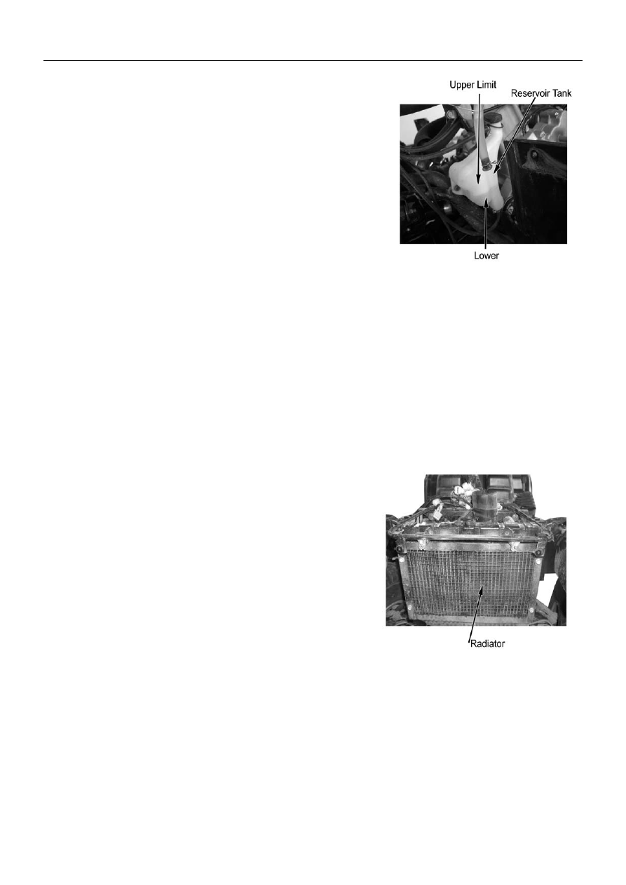
When the coolant level is below the LOWER limit,   

remove reservoir tank cap and add coolant till upper limit.   

(Add coolant or diluted original liquid).                                                                                                                                               

Recommended coolant: CFMOTO coolant 


Standard density: 50% 

( Freezing temperature of coolant varies according to the 

different mixture ratio. Adjust the mixture ratio according to 

the lowest temperature in the place where the vehicle is 

used.)


If the coolant reduces very fast, check if there is any leakage. 

The cooling system may be mixed with air when there is no   

coolant in the reservoir tank and the air should be discharged 

before adding coolant.


Coolant Leakage 

Check radiator hose, water pump, water pipes and joints for 

leakage.  

In case of any leakage, disassemble and do further check.   

(Refer to Chapter 4)   


Check the radiator hose for aging, damages or cracks. 


The rubber hose will naturally get aged after a period of service 

time. The aged hose may get cracked when the cooling system 

is heated. Nip the hose with fingers and check if there are any 

tiny cracks. 


In case of any abnormal, replace with a new hose. 


Check the clamps of the coolant pipes and hose.   

Tighten properly in case of any looseness. 


Check radiator fins for mud and dust clog or damage. 


Correct the bent fins; clean the mud with water and compressed 

air. When the damaged area of the radiator fin is over 20%, 

replace with a new radiator. 


  3-13 


                                                            3. Checks & Adjustment 

Check Water Temperature Gauge 


When engine is not working, the water temperature should be in 
the “0” position. Start the engine to check if the indicator works. If 
the indicator is not working, do the maintenance in time. 


Lighting System 

Adjusting headlight light beam 


Turn the headlight beam adjusting screw with a cross 
screwdriver and adjust the high/low beam to meet the 
requirement.         


 3-14 

                                                                                                                                  4. Cooling System 

Overhauling Info………………………………. 4-1 
Trouble Shooting……………………………… 4-2   
Check and Maintenance………………………4-3 
Reservoir Tank……………………. …………..4-5 

Adding Coolant…………………………………..4-7 
Cooling System Chart…………………………..4-10 


Overhaul Information 


Note 

 If the radiator cap is opened when the coolant temperature is above 100

, the pressure of coolant   

will drop and get boiled rapidly. The steam jet may cause danger and injury. Cover the cap with a 
piece of rag after the coolant temperature goes down and open the cap slowly. 
 

 Inspection of coolant should be done after the coolant is fully cooled. 


 Coolant is toxic. Do not drink or splash it to skin, eyes or cloth. 

If


coolant splashes in your eyes, thoroughly wash your eyes with water and consult a doctor. 

If coolant splashes on your clothes, quickly wash it away with water and then with soap and water. 

If coolant is swallowed, induce vomit immediately and see a physician. 

Store the coolant properly and keep it away from reach of children. 


 Check radiator fins for mud block and/or damage. Correct the bent fins. Clean off the mud with water 

and compressed air. Replace with a new one if the damaged fin area reached 20%. 


 The overhauling of the water pump can be done without removing the engine. 

 Add coolant through reservoir tank. Do not open the radiator cap except when disassembling the cooling 

system for adding or drainage of coolant. 

 Do not stain the plastic parts with coolant. In case of any coolant stains, flush with water immediately. 

 After disassembly of the cooling system, check the joints for leakage with a radiator cap tester (available in 

the market). 

 Refer to Chapter 10 for overhauling of temperature transducer. 


Inspection standard 

Item Standard 

Full capacity 

1140ml 

Reservoir tank capacity 

340ml 

Coolant 

Capacity 

Standard density 

30% 

Opening pressure of radiator cap 

108kpa(1.1kgf/cm

2

)


Valve open temperature 

72

±

2


Full open Temperature 

88


Thermostat 

Full open lift 

3.5-4.5mm 


Tightening torque 

Drainage bolt, water pump: 


      8N

·

m(0.8kgf

·

m) 

Thermoswitch                               


              10N

·

m(1.0kgf

·

m) 


  4-1 

                                                                                                                                  4. Cooling System 

Trouble Shooting 


Sharp rise of water temperature 


z

  Faulty radiator cap 

z

  Air in cooling system   

z

 Faulty 

water 

pump 

z

  Faulty thermostat (thermostat is not open) 

z

  Clogged radiator pipe or cooling pipes 

z

  Damage or clogged radiator fin 

z

  Coolant is not enough 

z

  Faulty or malfunction of fan motor 


No rise or slow rise of water temperature. 
 

Faulty thermostat (thermostat is not closed) 
Faulty circuit of water temperature display 


Coolant leakage 


z

 Faulty 

water 

seal 

z

  O-rings are aged, damaged or improperly sealed. 

z

  Washers are aged, damaged or improperly sealed. 

z

  Improper installation of pipes or hoses 

z

  Pipes and/or hoses are aged, damaged or improperly sealed 


4-2 

                                                                                                                                  4. Cooling System 

Check and Maintenance 


Checking coolant density 


Note: 
Open the radiator cap after coolant is fully cooled. 
 

Remove: 
--Front top cover (

2-4)  

--Radiator cap (counter clockwise). 
 
Check with a densimeter if the coolant density adapts to 
the local temperature. 
 
Check coolant for stains or impurities. 


Inspection of radiator cap 
Note 
Open the radiator cap after the coolant is fully cooled. 


Remove: 
--Front top cover (

2-4)  

--Radiator cap (

4-3). 


Note 
Apply coolant on the sealing surface of radiator cap 
before attaching the tester to the radiator cap.                                                                                                     


Install the radiator cap tester to the radiator cap; 
 
Apply the specified pressure (radiator cap opening 
pressure) for 6 seconds and make sure that there is drop in 
pressure. 


Opening pressure of radiator cap:   
 

108kpa(1.1kgf/cm

2


                              4-3 

                                                                                                                                  4. Cooling System 

 
Pressure testing of cooling system 
 

Install the radiator cap tester to the radiator cap; 
 
Apply the specified pressure (radiator cap opening 
pressure) for 6 seconds and make sure that there is drop in 
pressure. 

 
Note 
Do not apply pressure over the specified pressure 
[108kpa(1.1kgf/cm

2

)], or the cooling system may be 

damaged. 
 

In case there is any pressure leakage, check the pipe, joint 
parts, joints of water pump and drainage (

4-5). 


Replacing Coolant,    Air Discharge 


Preparation of coolant 
Coolant is toxic, DO NOT drink or splash it to skin, 
eyes, and clothes. 

If


coolant splashes in your eyes, thoroughly wash 

your eyes with water and consult a doctor. 

If coolant splashes on your clothes, quickly wash it 
away with water and then with soap and water. 

If coolant is swallowed, induce vomit immediately 
and see a physician. 


Store the coolant properly and keep it away from 
reach of children. 


Note  
Mix the coolant (undiluted) with soft water according 
to the temperature 5

 lower than the actual lowest 

local temperature.    


Coolant should be made from undiluted coolant with soft 
water. 
 

Standard density of coolant: 30%     


Recommended coolant: CFMOTO coolant   
(Direct application without having to be diluted) 
 

Drainage of coolant 

Remove radiator cap cover 

Note 
Open the radiator cap after the coolant is fully cooled.                     


Remove:  
--Front top cover(

2-8) 

--Radiator cap. (

4-3) 


    4-4 

                                                                                                                                  4. Cooling System 


Remove drain bolt 

 
Remove drain bolt, seal gasket from water pump, and drain 
coolant. 
After drainage, assemble with a new seal gasket, drain bolt 
and tighten.      


Reservoir Tank 

 
Remove: 
--Seat (

2-3) 

--Left side panel (

2-6) 

--2 Mounting bolts 
--Water hose of reservoir tank   
 
Remove reservoir tank; discharge coolant;     
Flush reservoir tank. 

reservoir tank


Install reservoir tank; 

bolt


Install water pipe.                                             


4-5 

                                                                                                                                  4. Cooling System 

Adding Coolant 

 
Add coolant through filling port. 

filling port 


Start the engine and discharge air from cooling system.   
Check from filling port that air is fully discharged from 
cooling system and install the radiator cap. 
 
Remove reservoir tank cap and add coolant till the upper 
limit. 


Note: 

UPPER LIMIT 

Check coolant level when the vehicle is on an even 
ground. 

LOWER LIMIT


Air Discharge 

Discharge the air from cooling system according to the 
following steps: 
1.  Remove drain bolt (

4-5), discharge air and install it. 

2.  Start the engine and run it several minutes at idle 

speed; 

3.  Quickly increase throttle 3~4 times to discharge air 

from cooling system; 

4.  Add coolant till filling port; 
5.  Repeat step 2 & 3 till no more coolant can be refilled; 
6.  Check coolant level in reservoir tank and refill till upper 

limit.  

7.  Install reservoir tank cap. 


    4-6


                                                                                                                                  4. Cooling System 

Cooling System Chart 


4-7                       


                                    5. Removal and Installation of Engine, Drive Train and Gearshift Unit 

Overhaul Info…..……………………………..5-1   
 
Engine Removal and Installation…………...5-2     
 

Removal and Installation of Front and Rear  
Axle……………………………………………….5-5 
Removal and Installation of Gearshift Unit……5-7 


Overhaul info 


Operation cautions 

Securely support the ATV with bracket when removing or installing engine. 

Take care not to damage frame, engine body, bolts and cables. 

Wrap the frame to avoid any possible damage when removing or installing the engine. 

Following operation doesn’t require removal of engine from the vehicle: 

Oil pump 

Carburetor, air filter   

Cylinder head cover, cylinder head, cylinder body, camshaft 

CVT system, CVT cover 

Gearbox 

Right side cover, AC magneto, water pump 

Piston, piston ring, piston pin 

Following operation require removal of engine from vehicle: 

Crankshaft 


Tightening torque: 

Engine front upper mounting bolt:               


35N

45N

·

Engine front rear mounting bolt: 


        40

50N

·

Bolt, engine front rear mounting bracket                35

45N

·

Bolt, engine front upper mounting bracket               35

45N

·


 5-1 

                  5. Removal and Installation of Engine, Drive Train and Gearshift Unit 


Engine Removal 


Remove: 
--Plastic(

Chapter 2) 

--Air Filter(

Engine service chapter) 

--Carburetor (

Engine service chapter) 

--Clamp 
--Water Inlet Hose 


Remove screw 
 
Remove gearshift rod 


Remove clamp 
 
Remove water outlet hose 


Remove Sleeve. 
Remove connectors of magneto, enriching device lead, 
pickup, water temperature transducer, gear sensor as 
illustrated on the right. 


5-2 


                  5. Removal and Installation of Engine, Drive Train and Gearshift Unit 


Remove spark plug cap from cylinder.     


Remove protection sleeve of starter relay. 
 
Remove Nut. 
 
Disconnect positive wire of starter relay. 


Remove nut. 
 
Remove negative wire of starter relay.             


Remove Bolt 1 and Nut 1 of upper engine hanger. 


    5-3 

                  5. Removal and Installation of Engine, Drive Train and Gearshift Unit 


Remove Bolt 2 and Nut 2 of upper engine hanger. 


Remove Bolt 1 and Nut 1 of lower engine hanger. 


Remove Bolt 2 and Nut 2 of lower engine hanger. 


 5-4 

                  5. Removal and Installation of Engine, Drive Train and Gearshift Unit 


Engine Installation 

Put engine onto the frame

install the two lower mounting bolts and nuts. 

Then install the upper and lower engine hangers.   
 

Tightening torque: 

  Engine upper hanger bolt:35

45N.m 

Engine lower hanger bolt:50

60N.m 

 
Install: 
--Water outlet and inlet hoses to engine with proper clamps. 
--Positive and negative starting wires to engine. 
--Connect all the connectors.   
--Spark plug cap. 
--Gearshift rod to engine. 
--Air filter, carburetor and removed parts. 
                                                                                                           

Removal and Installation of Front and Rear Axle 

 
Support the vehicle with jack, make sure the vehicle will not fall. 
Remove:  
--Plastic parts for frame(

Chapter 2) 

--Front and rear wheels and arms(

Chapter 6) 

--Air filter(

engine service chapter) 

--Carburetor(

engine service chapter) 

--Engine 
--Rear brake caliper(

7-4) 


1.  Nut     2. Bolt 1    3. Bolt 2    4. Front Axle    5. Bolt 3     6. Front Drive Shaft 
7. Clamp        8. Breather Hose, Front Axle    9. Bolt 4   10. Rear Axle  
11. Breather Hose, Rear Axle   
12. Rear Brake Disk    13. Bolt 5    14. Rear Drive Shaft                                 

5-5 

                  5. Removal and Installation of Engine, Drive Train and Gearshift Unit 


Remove nut and bolt of front axle from frame.   


Remove nut and bolt of rear axle from frame. 


      5-6                       

                  5. Removal and Installation of Engine, Drive Train and Gearshift Unit 

Remove the 18 bolts


for drive shafts   

and front and rear axles. 
(Refer to P. 5-5, Bolt 3 of Part No.5) 
 
 
Remove: 
--Front and rear axles, drive shafts, rear brake disc 


Installation: 

Reverse the removal procedure for installation. 
 

Tightening torque: 

Bolt, front axle

40-50N.m 

Bolt, rear axle

40-50N.m 

Bolt, front and rear drive shafts

40-50N.m 


Gearshift Unit 

Remove: 
--Left and right side panel

(→

2-6


--Fuel tank top cover (

2-8) 

--Front fender(

2-8) 

--Bolt 1 
--Gearshift rod 


Remove the 2 bolts 
 
Remove gearshift unit 
 

Installation: 

Reverse the removal procedure for installation. 
 
Make sure that gearshift is flexible. 
 
In case of any inflexibility, adjust the gearshift rod to 
ensure the gear engagement. 


                    5-7


Content      ..     2      3      4      5     ..