CFMoto ATV Terralander CF800-2. Service Manual - part 5
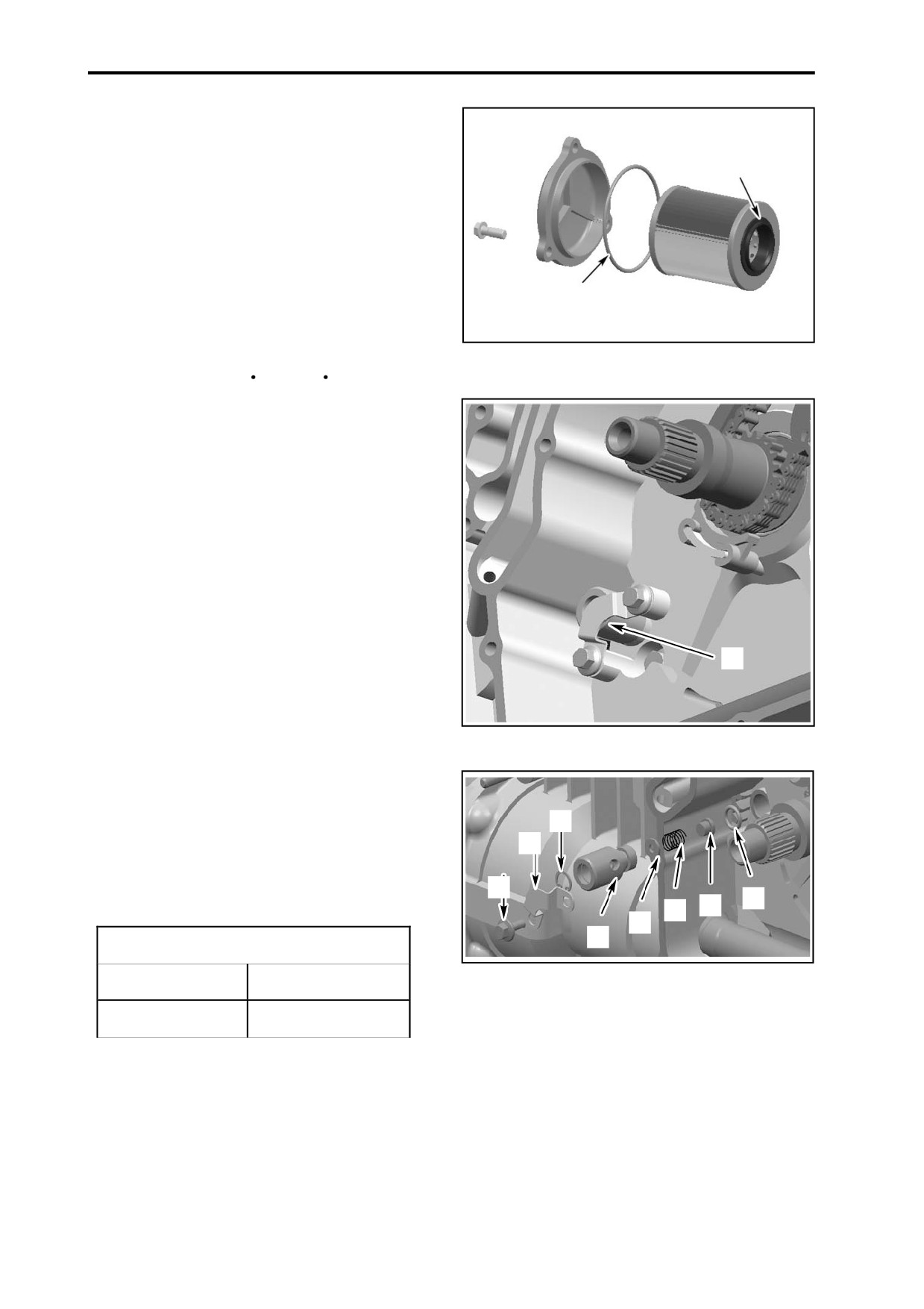
Oil Filter Element Installation
Install a NEW o-ring on oil filter cover;
2
Apply engine oil on o-ring and the end of filter;
Install the element into oil filter bore;
1
Install the oil filter cover on the engine.
1.Apply a light coating of oil here
Torque screws to 10N m(89Ibf in).
2.Apply a light coating of oil here
OIL PRESSURE REGULATOR VALVE
Engine oil pressure valve is located on engine PTO
side(under CVT air guide).
The oil pressure regulator valve works when the oil
pressure exceeds 450kPa(65PSI).
Removal
1
Remove screws no.1 and the holding strip;
Remove oil pressure regulator valve.
1.Engine Oil Pressure Regulator Valve
Inspection
Inspect oil pressure regulator valve no.4,spring seat
no.5,plunger no.7,o-ring no.8 for damages.Replace if
3
necessary.Circlip no.3 must be replaced.Check
2
spring no.6 for free length.If the length is out of the
following values,replace it.
1
8
7
6
5
4
Spr in g F ree Length
New Nominal
17mm
1.Bolt
2.Holding Strip
3.Circlip
Service Limit
16mm
4.Oil Pressure Regulator Valve
5.Spring Seat
6.Spring
7.Oil Plunger
8.O-ring
Installation
Reverse the removal procedure for installation.
10-8
10 ENGINE LUBRICATION SYSTEM
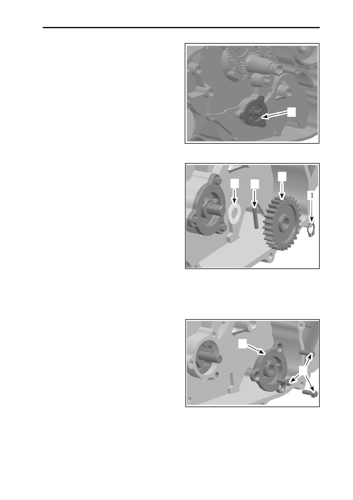
OIL PUMP
Oil pump is located on the engine MAG side(under
magneto cover).
1
1.Oil Pump
Removal
2
Remove magneto cover and related parts(see
4
3
Magneto Cover Removal);
Remove magneto rotor(see Rotor Removal);
Remove circlip,oil pump gear,needle pin,thrust
washer in turn;
1.Circlip
2.Oil Pump Gear
3.Needle Pin
4.Thrust Washer
Remove oil pump cover screws and oil pump cover;
2
Remove pump shaft with inner rotor and outer rotor.
1
1.Screws
2.Oil Pump Cover
10-9
Inspection
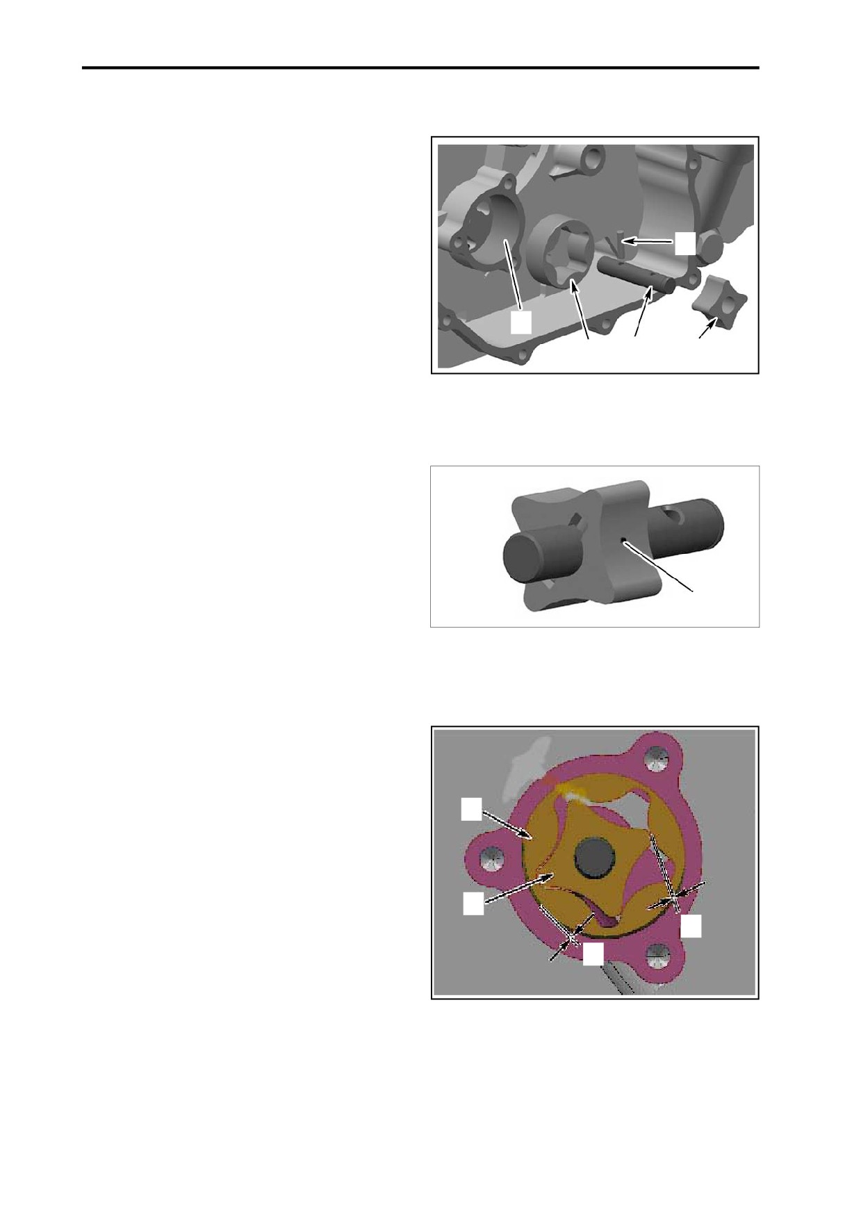
Inspect oil pump for marks or other damages.Check
for scratches in crankcase between outer rotor and
oil pump bore.If so,replace damaged parts;
4
1
3
5
2
1.Oil Pump Bore
2.Outer Rotor
3.Oil Pump Shaft
4.Needle Pin
5.Inner Rotor
Check inner rotor for corrosion pin holes or other
damages.If so,replace oil pump shaft assembly.
1
1.Pittings on the teeth
Using a feeler gauge,measure the clearance of inner
and outer rotors plus the clearance between outer
rotor and oil pump bore as shown.
2
1
If clearance between inner rotor and outer rotor
A
exceeds the tolerance,replace the inner and outer
rotor.
A
Ensure to also check oil pump cover,if damaged,
replace the oil pump cover.
1.Inner Rotor
2.Outer Rotor
A.Service Limit:0.25mm
10-10
10 ENGINE LUBRICATION SYSTEM
If clearance between outer rotor and its bore in
crankcase exceeds the tolerance,replace outer rotor
assembly and/or crankcase.
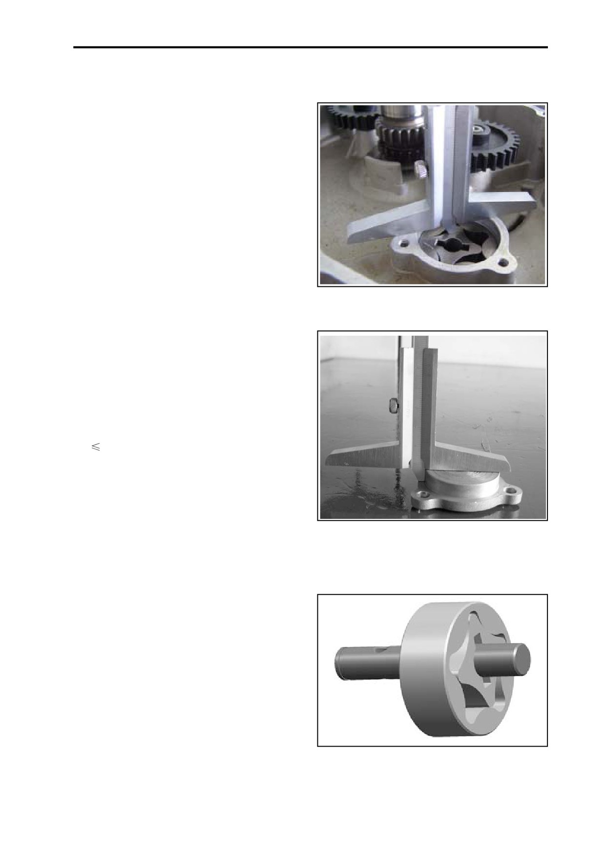
Using a depth gauge,measure the axial clearance of
the oil pump as shown.Difference between measure-
ments should not exceed 0.1mm(0.008in).If so,
replace the inner and outer rotor.
Measurement ”A”
Using a depth gauge,measure the axial depth of the
part that extends to oil pump bore as shown.
A-B
0.2mm
NOTE:When the axial clearance of the oil pump
shaft assembly increases,the oil pressure
decreases.
Measurement ”B”
Installation
Reverse the removal procedure for installation.
NOTE:No marks on inner and outer rotor.When
installating outer rotor,no secified direction for outer
rotor.
After installation,check for smooth operation of
the oil pump assembly.
Final Test
After engine is completely reassembled,start engine
and make sure oil pressure is within specifications
(refer to Engine Oil Pressure above.)
10-11
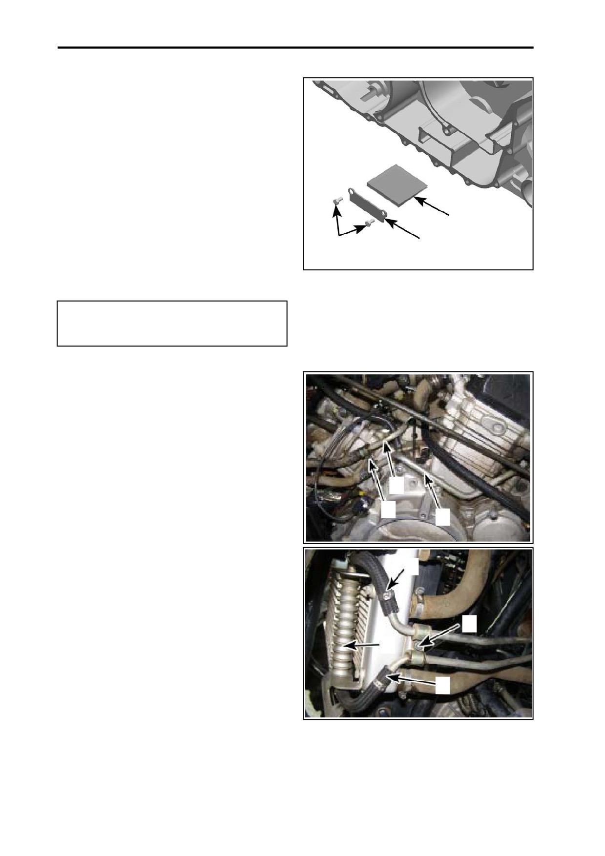
ENGINE OIL STRAINER
The engine oil strainer no.7 is located on the bottom
of left crankcase half.
Removal
Refer to Chapter 8.
1
Cleaning and Inspection
2
3
Clean engine oil strainer with a part cleaner then
use an air gun to dry it.
1.Oil Strainer
2.Retaining Plate
WARNING
3.Screws
Always wear eye protector.Chemicals can
cause a rash break out and injure your eyes.
Installation
Reverse the removal procedure for installation.
OIL DELIVERY PIPE AND OIL RADIATOR
1
4
2
1
4
3
2
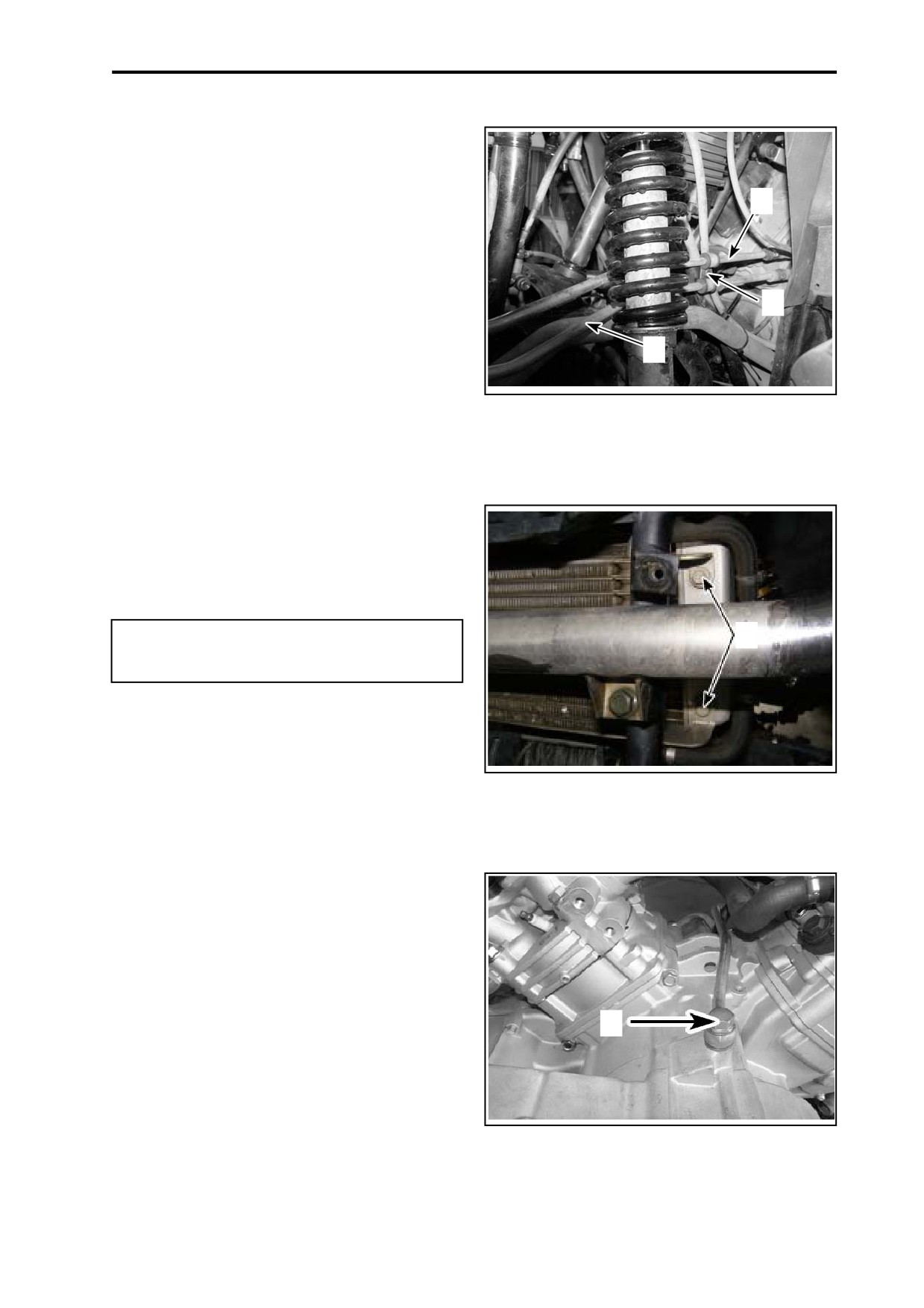
1. Inlet Oil Delivery Pipe
2.Outlet oil Delivery Pipe
3.Oil Radiator
4.Oil Delivery Pipe Holding Screw
10-12
10 ENGINE LUBRICATION SYSTEM
Removal
1
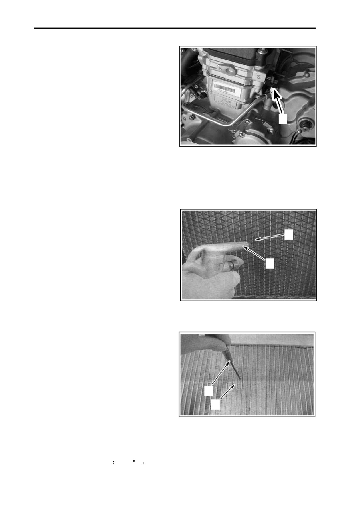
Remove engine inlet and outlet oil delivery pipe
retaining screws;
Remove engine inlet and outlet oil delivery pipes.
3
2
1.Inlet Oil Delivery Pipe
2.Outlet Oil Delivery Pipe
3.Holding Screw
Remove the 4 mounting bolts then oil radiator;
CAUTION:Drain the oil in the oil delivery
1
pipe and oil radiator before removal.
1.Oil Radiator Mounting Bolts
Remove engine inlet and outlet union bolts no.1;
Remove inlet and outlet oil delivery pipes.
1
1.Union Bolt
10-13
1
Oil Delivery Pipe Inspection
1.Engine Oil Outlet Union Bolt
Inspect oil delivery pipe for leaks,cracks and other
damages.If so,replace it;
Always replace oil pipe clamp after removal.
Oil Radiator Inspection and Cleaning
Inspect radiator for deformation and bulge.If so,replace
1
it;
Use an air gun to clean the dirt on radiator fins;
2
1.Oil Radiator
2.Air Gun
Inspect radiator fins for deformation.If so,use a small
screw driver to repair the fins.
1
Oil Delivery Pipe and Oil Radiator Installa-
tion
2
1.Screw Driver
Reverse the removal procedure for installation.
2.Oil Radiator
Union bolt tightening torque
25N m
10-14
11 MAGNETO SYSTEM
MAGNETO SYSTEM
11
Description
P/N
Page
Magneto Rotor Remover
0800-031000-922-001
6
Description
P/N
Page
Engine Oil
Threadlocker
Loctite 5699(Silicone Sealant)
11
11-1
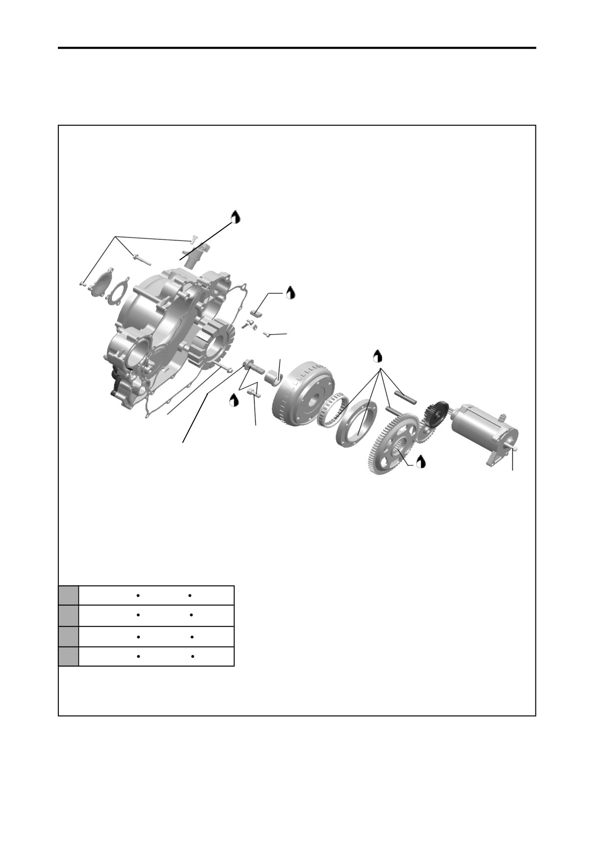
Engine Oil
T3
Loctite 5699
T4
Engine Oil
Threadlocker
T3
T2
T1
Engine Oil
T3
T1
105N m(78lbf ft)
T2
30N m(22lbf ft)
T3
10N m(89lbf in)
T4
4N m(36lbf in)
11-2
11 MAGNETO SYSTEM
GENERAL
Always perform the electric tests before removing or
installing whatever component.
During assembly/installation,use the torque values and
service products as in the exploded view. Clean
threads before applying threadlocker.Refer to LUBRI-
CANTS AND SERVICE PRODUCTS at the begining
of this manual for complete procedure.
WARNING
Torque wrench tightening specification must
strictly be adhered to.Locking devices.(e. g .:
locking tabs ,elastic stop nuts,cotter pins , etc.)
must be installed or replaced with new ones
where specified.If the efficiency of a locking
device is impaired ,it must be renewed.
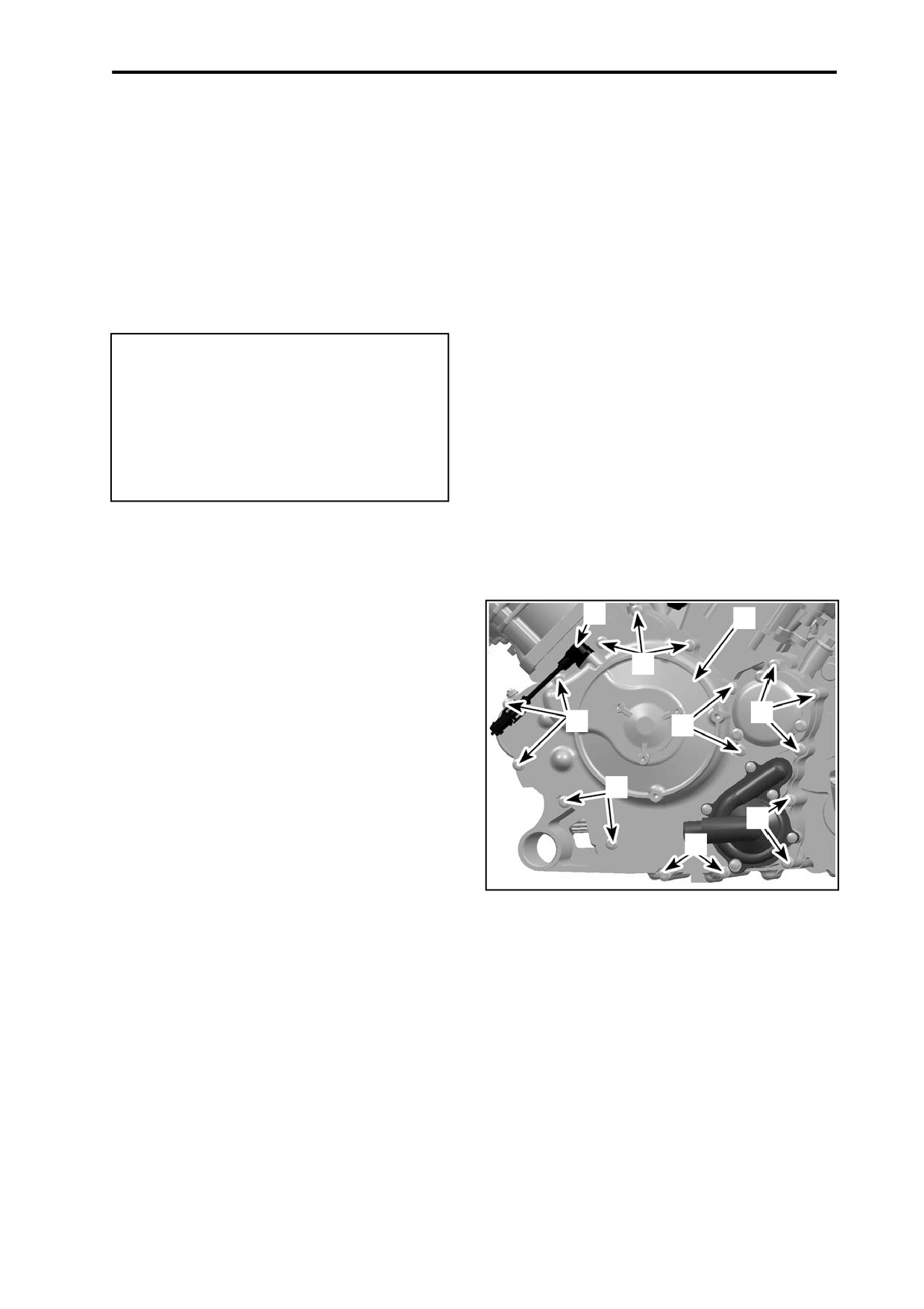
MAGENTO COVER
Removal
3
1
Drain engine oil (refer to LUBRICATION SYSTEM
2
and cooling system) and coolant;
11
2
2
2
Remove crankshaft position sensor(CPS);
Disconnect magneto connector;
2
Remove magneto cover retaining screws;
2
Remove magneto cover.
2
1.Magneto Cover
2.Retaining screws
Inspection and Cleaning
3.CPS(crankshaft position sensor)
Check magneto cover for cracks or other damages.
Replace if necessary.
Check working condition of rolling bearing.Replace if
necessary.
11-3
NOTE:
Clean all metal components in a nonferrous metal
cleaner.Use suitable tool to remove gasket.
WARNING
Wear safety glasses and work in a well ventilated
area when working with strong chemical
products. Aslo wear suitable non-absorbent
gloves to protect your hands.
Installation
For installation, reverse the removal procedure.Pay
attention to the following.
1
NOTE:
At installation replace magneto cover gasket.
Apply sealing compound on startor cable grommet
as shown on the right.
apply grease on bearing
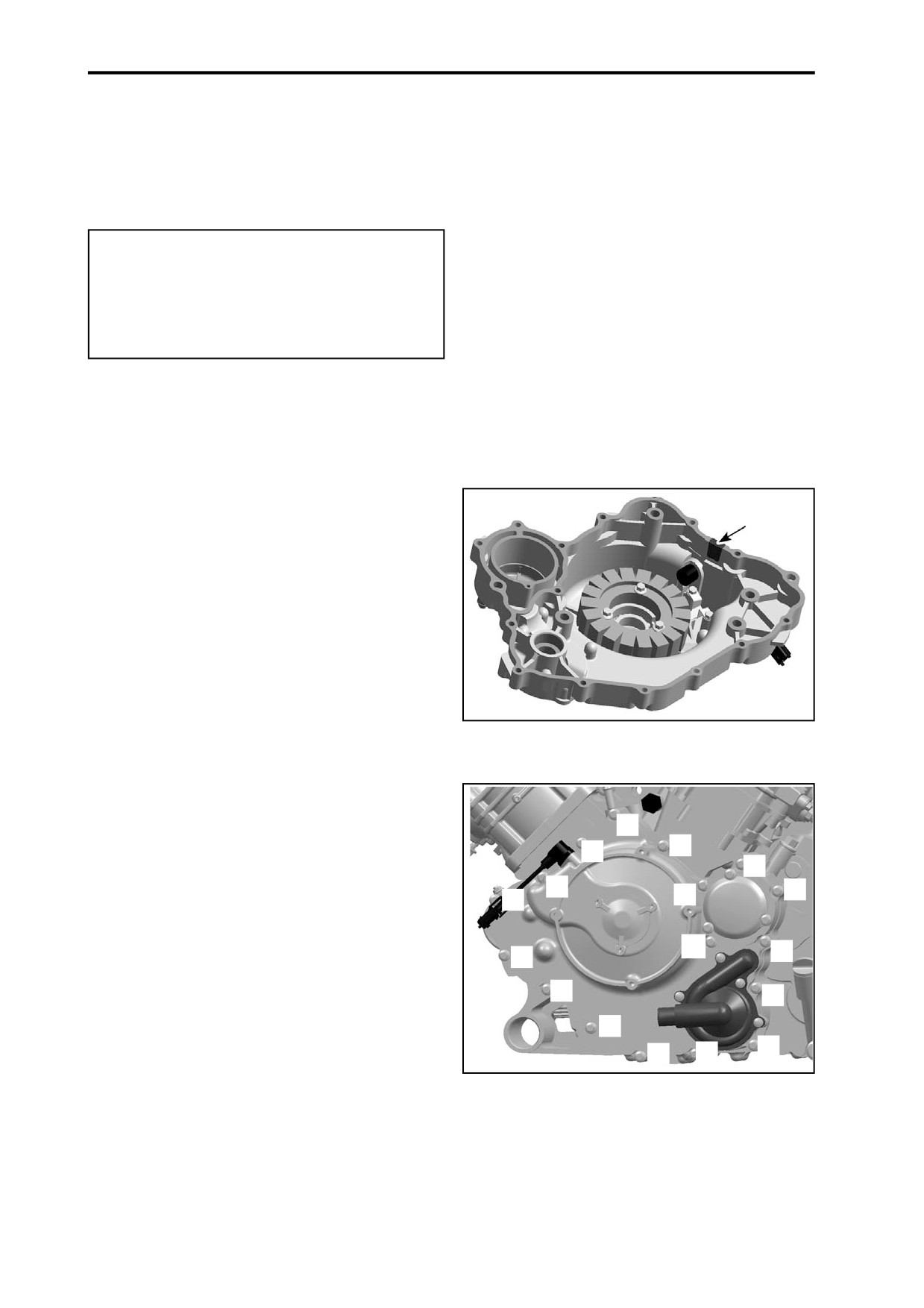
1.Apply Loctite 5699(Silicone Sealant)
17
1
16
5
Tightening sequence for screws on magneto cover is
15
6
4
as per following illustration.
14
3
7
13
12
8
Refill engine with recommended oil and coolant.
2
9
11
10
Tightening Sequence
11-4
11 MAGNETO SYSTEM
STATOR
1
Removal
3
Magneto Cover
Removal
4
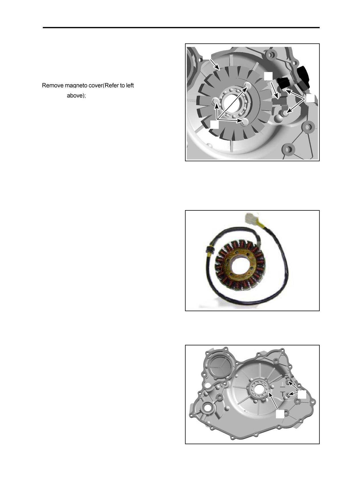
Remove screws securing holding strip;
2
Remove stator retaining screws then the stator.
1.Stator
2.Stator retaining Screws
3.Holding Strip
4.Holding Strip screws
Inspection
Check stator condition, if damaged replace it.
Check if stator wires are brittle ,hard or otherwise
11
damaged.
Stator Installation
1.Stator
For installation, reverse the removal procedure.
CAUTION:
When installing the stator take care that the
cable is in place(guide for the wire).
1
NOTE:
There is only one position for the stator(notch in the
2
magneto housing cover )
1.Threads for cable holding strip
2.Notch for stator
11-5
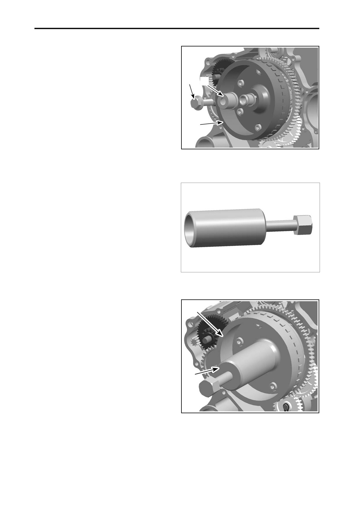
ROTOR
Removal
1
2
Remove magneto cover.(Refer to MAGNETO
COVER above );
Remove screw and washer securing rotor to
3
crankshaft.
1.Bolt
2.Washer
3.Rotor
Install magneto puller and then remove rotor.
1.Magneto Puller
NOTE:
1
Use grease to magneto puller end prior to install rotor
puller in order to protect crankshaft.
Screw magneto puller bolt to remove rotor.
2
1.Rotor
2.Magneto Puller
11-6
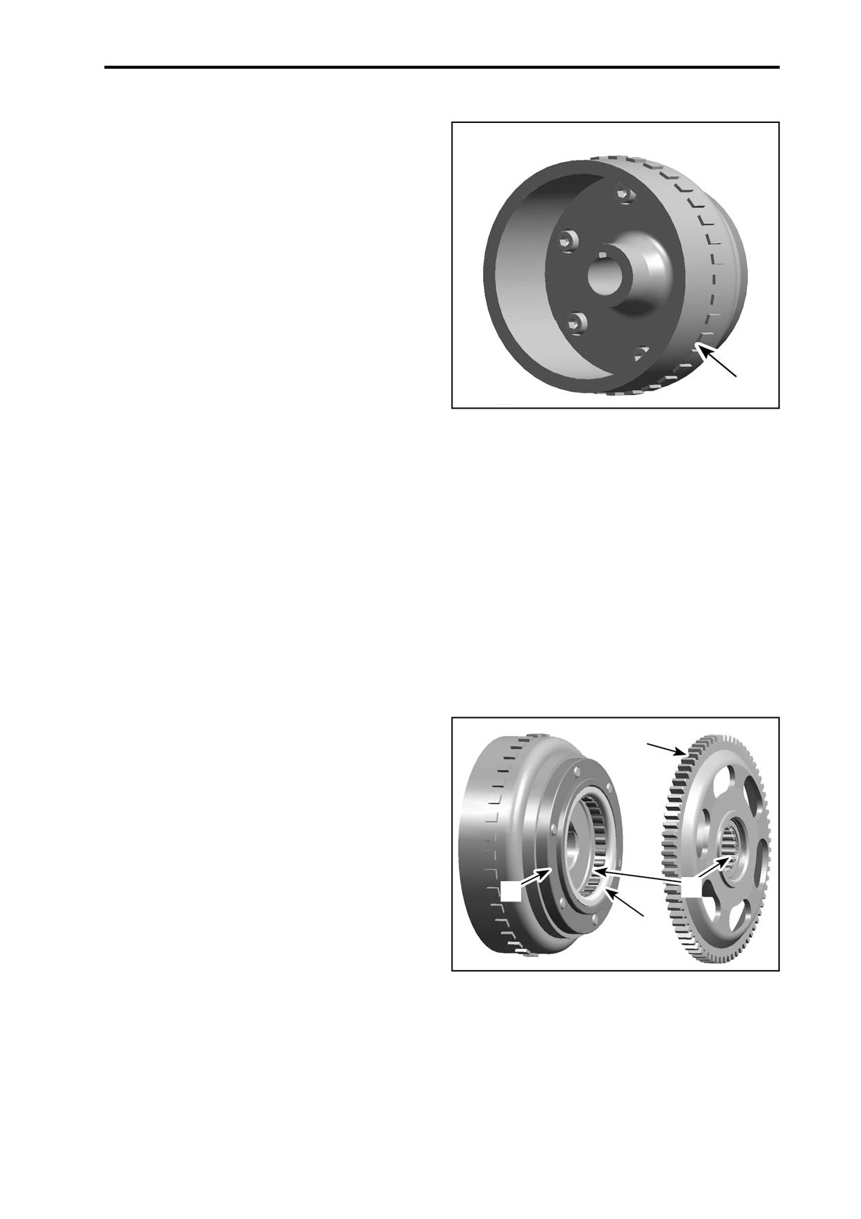
11 MAGNETO SYSTEM
Inspection
Check inner side of rotor for scratches or other
damages.
Check keyway of rotor for wear or damages.
Check if trigger wheel teeth are bent or otherwise
damaged.
Check woodruff key and keyway on the crankshaft
1
for wear or damages.
1.Rotor with trigger wheel
Replace parts as necessary.
Installation
For installation,reverse the removal procedure.
Pay attention to the following.
Clean crankshaft taper and rotor with cleaner.
11
3
Oil sprag clutch in sprag clutch housing and install
sprag clutch gear.
Slide rotor onto crankshaft.The woodruff key and the
keyway must be aligned.
4
2
1
1.Sprag Clutch
2.Sprag clutch housing
3.Sprag clutch gear
4.Apply engine oil here
11-7
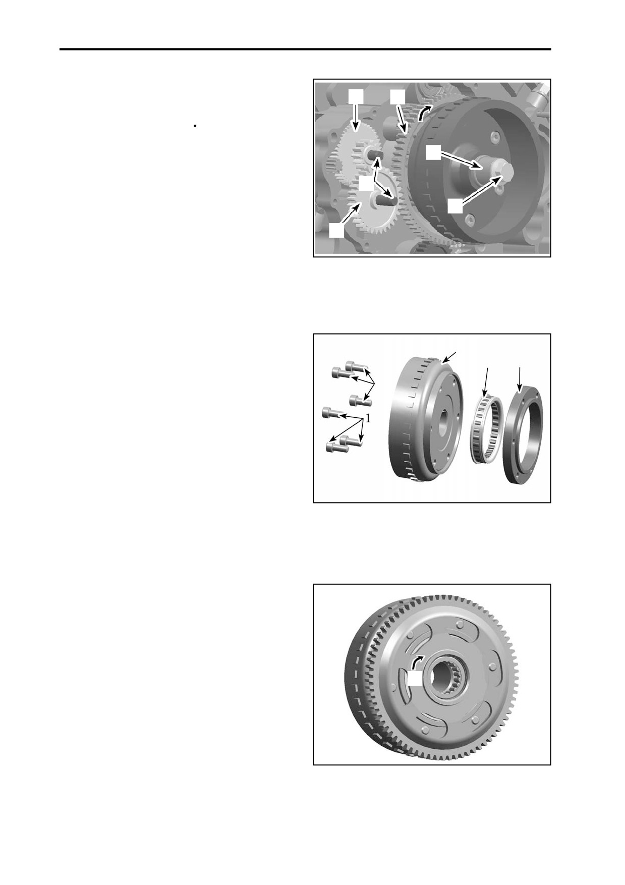
Slide spacer bush onto crankshaft and
1
4
torque the bolt to specified value.
Bolt tightening torque:105N m
Rotate starter double gear counterclockwise to align
5
intermediate gear teeth with clutch sprag gear teeth.
2
6
NOTE:Breather shaft end with chamfer should
3
faces outside.
1.Double Gear
2.Breather Gear Shaft
3.Intermediate Gear 4.Sprag Clutch Gear
SPRAG CLUTCH
5.Spacer Bush
6.Bolt
NOTE:It is not necessary to remove if sprag clutch
has no problem.
2
3
4
Sprag Clutch Removal
1
Remove magneto cover (refer to MAGNETO
COVER above);
Remove rotor(refer to ROTOR above);
Remove sprag clutch gear;
1.Bolt
Remove sprag clutch housing screws and sprag
2.Rotor
clutch housing.
3.Sprag Clutch
4.Sprag Clutch Housing
Sprag Clutch Inspection
Perform a functional test of the sprag clutch.To do
so ,rotate driven gear in sprag clutch.
Inspect sprag clutch and sprag clutch housing for
1
wear and damage.
NOTE:
Sprag clutch must look in counterclockwise direction.
Sprag clutch,housing and gear must be replaced at
the same time ,if damaged.
Sprag Clutch Functional Test
1.Lock Direction
11-8
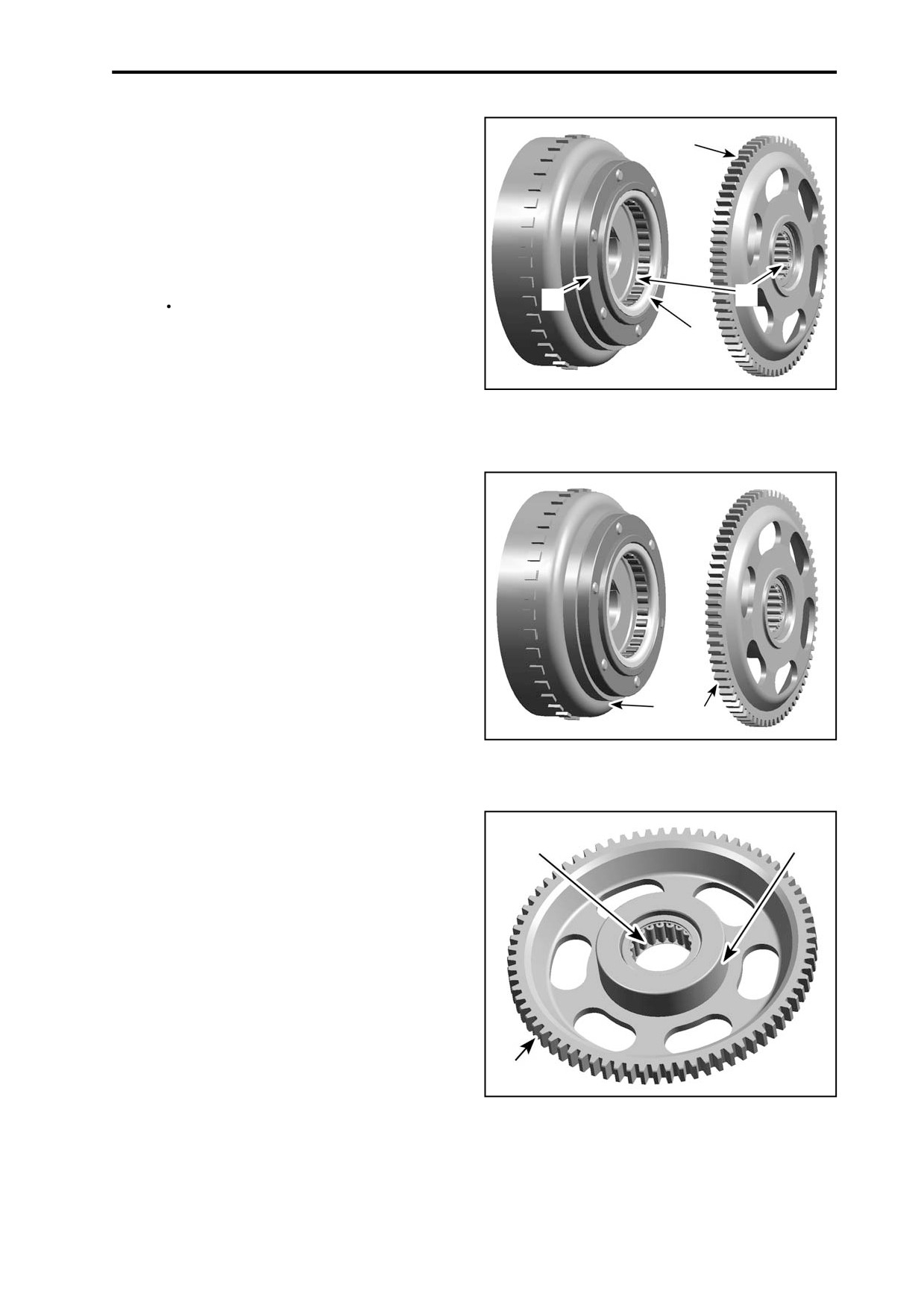
11 MAGNETO SYSTEM
Sprag Clutch Installation
For installation,reverse the removal procedure .
3
Pay attention to the following details.
Apply threadlocker on threads of sprag clutch
housing screws.
Install rotor then torque sprag clutch housing screws
2
4
to 30N m.
Apply engine oil on sprag clutch and inside sprag
1
clutch gear hole.
1.Sprag Clutch
2.Sprag Clutch Housing
3.Sprag Clutch Gear
4.Apply engine oil here
SPRAG CLUTCH GEAR
Removal
Remove rotor (refer to ROTOR above);
Pull sprag clutch gear from the rotor.
11
1
2
1.Rotor
Inspection
2.Sprag Clutch Gear
Inspect gear,especially teeth and sprag clutch
collar,for wear and other damages.
3
2
Check needle bearing condition;
Replace Drive Gear if necessary.
Installation
Reverse the removal procedure for installation.
1
NOTE:
Apply engine oil on needle bearing and collar of drive
INSPECT
gear.
1.Teeth
2.Collar
3.Needle Bearing
11-9
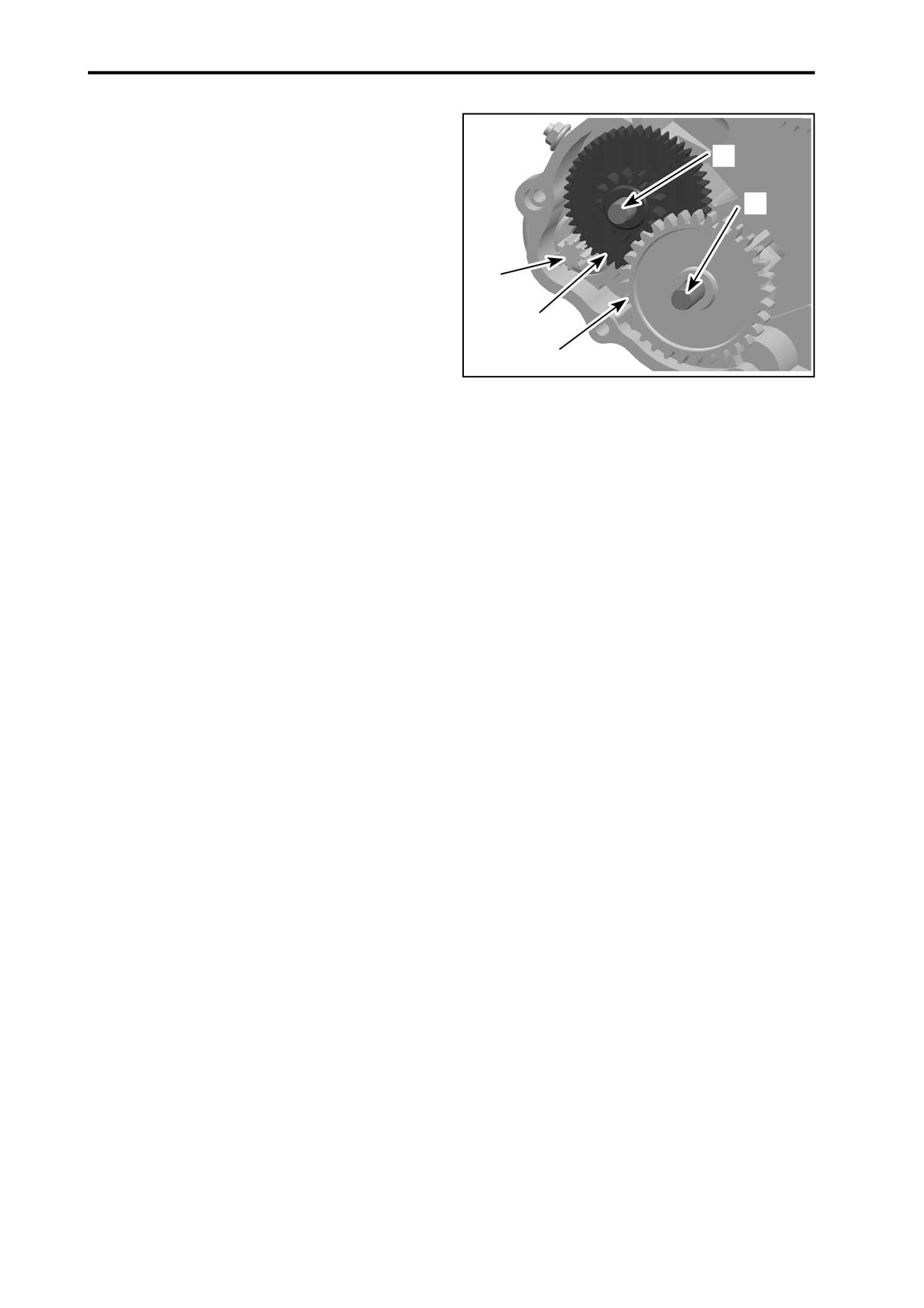
STARTER DRIVE GEARS
4
The starter gears are located on the engine MAG
side behind the magneto cover.
4
Removal
3
Remove magneto cover (refer to MAGNETO
2
COVER above);
1
Remove breather shafts,double gear,intermediate
1.Intermediate Gear
gear.
2.Starter Double Gear
3.Starter Gear
Inspection
4.Breather Shaft
Inspect gears and shafts for wear and damage.
Installation
Reverse the removal procedure for installation.
NOTE:
Apply engine oil on every gear shaft and teeth.
11-10
12 FRONT WHEELS,BRAKE,SUSPENSION,STEERING
Check&repair information…………12-1
Brake system…………………………12-4
Troubleshooting………………………12-2
Front suspension………………… ……12-7
Front wheel……………………………12-3
Steeri ng system………… ……………12- 12
12
MAINTENANCE INFORMATION
Operation Cautions:
CAUTIONS:
z Securely support the vehicle when doing check and repair
z Do not overexert on the wheel, avoid any damage to the wheel.
z When removing tire, use the special tire lever and rim protector.
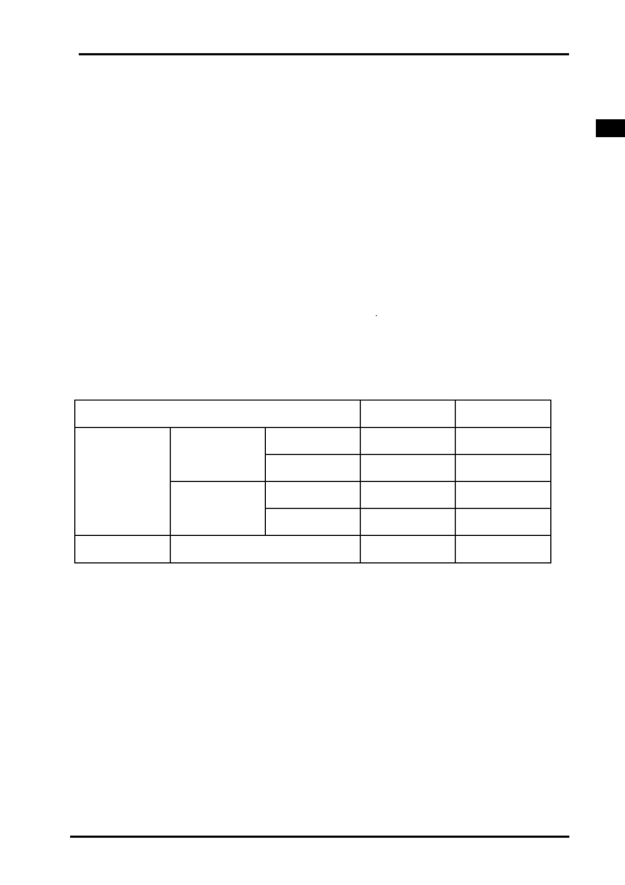
Maintenance Standard
Item
Standards
Service Limit
Radia l
0.8mm
2.0mm
Wheel Runout
Axial
0.8mm
2.0mm
Front Whee l
Tread Depth
-
3.0mm
Tire
Tire Pressure
45kPa
-
Front Brake
Brake Lever Free Play
0 mm
-
Tightening Torque
Nut, steering tie-rod
GB9457 M10x1.25
(30~40) Nz m
Lock nut, steering stem
GB6187 M14x1.5
(100~120) Nz m
Bolt, front brake disc
901-08.00.03
(25~35) Nz m
Bolt, front caliper
GB5789 M8x16
(15~25) Nz m
Axle nut
901-07.00.03
(15~25) Nz m
Bolt, front shock absorber
GB5789 M10x1.25x50,GB5789 M10x1.25x70
(15~25) Nz m
Wheel nut
901-07.00.02B
(70~80) Nz m
Bolt, A-arm
GB5789 M10X1.25X70
(40~50) Nz m
12-1
SERVICE TOOLS
Wheel cannot turn freely
z
Faulty wheel bearing
z
Rod, bearing remover
z Wheel installed improperly
z
Head 10mm, bearing remover
z
Handle A, driving tool
z Brake drag
z
Sleeve 28x30, driving tool
Front suspension too shoft
z Guide tool 10mm
z Weakened front shock absorber
z Locknut spanner
z Tire pressure is too low
z Bearing remover set
Front suspension too hard
z Rotor puller
z Front shock absorber is damaged
z Remover shaft
z Tire pressure is too high
z
Remover hammer
z Assembling tool shaft
Noise from front shock absorber
z Faulty front shock absorber
z Loosened tightening parts of front shock
absorber
Poor brake performance
z
Faulty brake adjustment
z
Stained brake disc
z
Brake pads worn
TROUBLESHOOTING
Heavy steering
z Upper thread is over tightened
z Steering bearing is damaged or worn
z Inner&outer bearing races are damaged
or not well tightened.
z Steering stem is distorted
z Low tire pressure
z Tire worn
Excessive handlebar free play
z Steering bearing is damaged or not well tightened.
z LH and RH shock absorber not matched
z Deflected tires
z Deformed frame
z Worn tire
z Shaking wheel bearing
Severe front wheel runout
z Wheel rim distorted
z Faulty wheel bearing
z Faulty tires
z mproper balance of wheels
z Imporper tightening of wheel shaft
12-2
12 FRONT WHEELS,BRAKE,SUSPENSION,STEERING
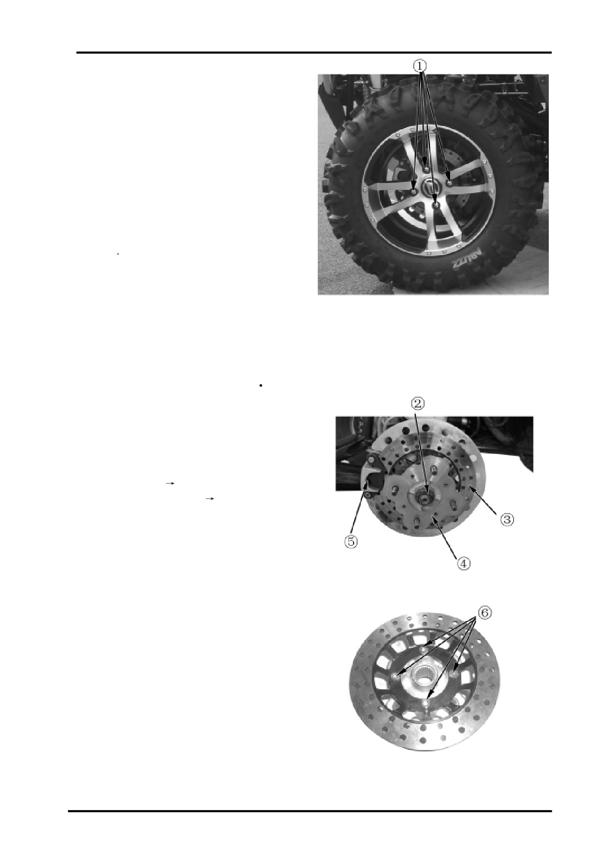
FRONT WHEEL
Removal
Securely support front wheels;
Remove wheel cap;
Remove the 4 wheel nuts no.1;
Remove front wheel.
Rim&Inspection
Check rim for damages,deformation,nicks.If any ab-
normal condition has been found,replace it.
Slowly turn wheel,use a dial gauge to measure the
rim runout
Service limit:
2.0mm (Axial)
2.0mm
(Radial)
Installation
Press rim into tire with special tool;
Fix wheel on the hub;
Wheel nuts tightening torque:70-80 N m
FRONT WHEEL HUB
Removal
Remove front wheel (
12-3);
Remove front brake caliper 5 (
12-4);
Remove rim axle nut no.2;
Remove brake disc and hub together;
Remove the 4 brake disc bolts no.6;
Remove front wheel hub no.4.
Installation
Reverse the removal procedure for installation.
Tightening torque of axle nut : 110-130N.m
Tightening torque of brake disc bolts no.6: 25-35N. m
(apply threadlocker)
12-3
FRONT BRAKE SYSTEM
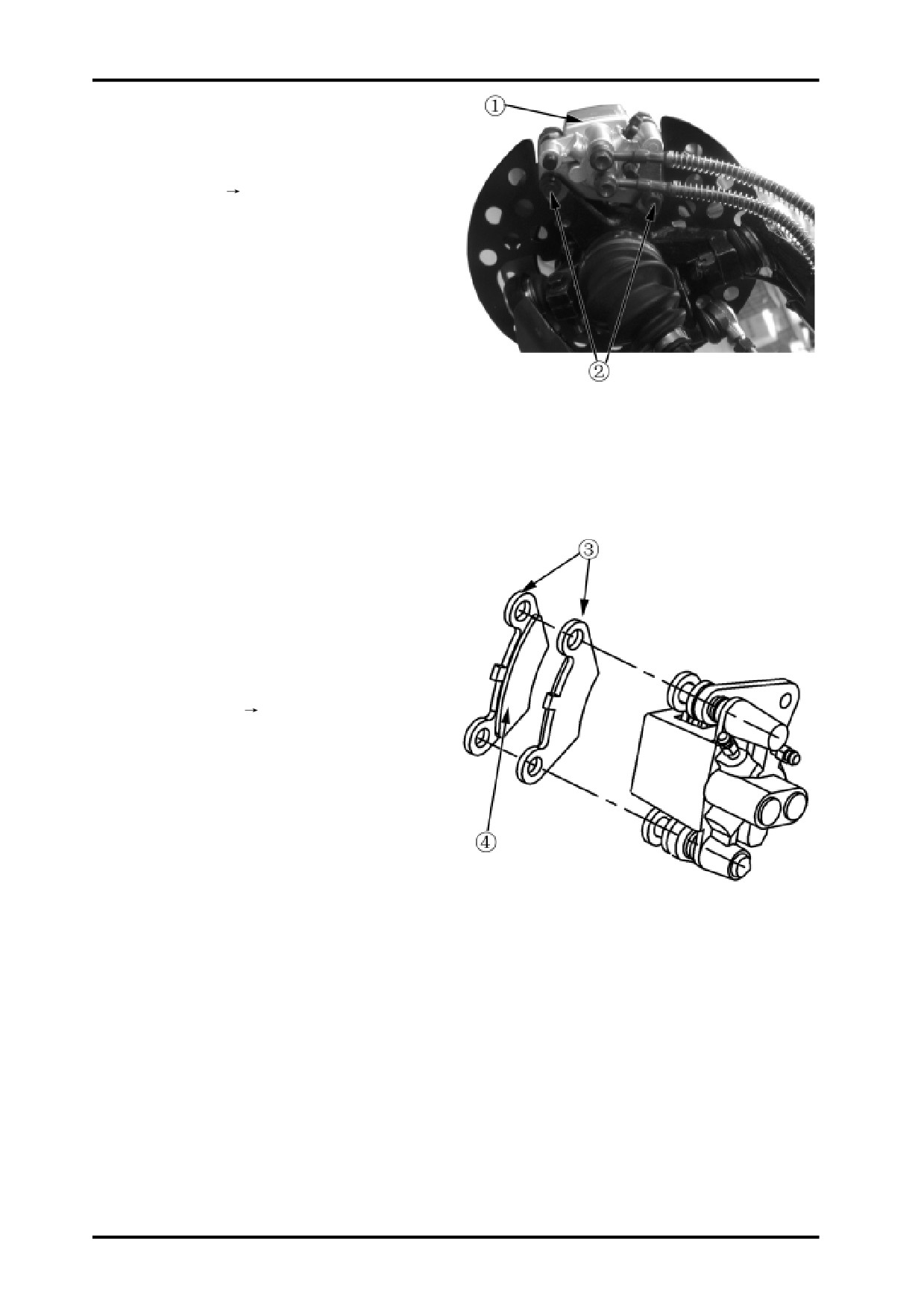
Front Brake Caliper
Removal
Remove front wheel(
12-3);
Remove the two bolts no.2;
Remove caliper no.1.
Inspection
Check any cracks of brake calipers and oil
leaks from tightening areas.Replace if necessary.
Installation
Tightening torque of brake caliper bolt: 15-25N.m
(Apply threadlocker)
BRAKE PADS
Removal
Remove brake caliper (
12-4);
Remove main sliding shaft of brake pads with allen
wrench;
Remove brake pads;
Measure thickness of brake pad friction surface no.4,
if it is less than 1mm, then replace both pads at the
same time.
12-4
12 FRONT WHEELS,BRAKE,SUSPENSION,STEERING
BRAKE DISC
Removal
Remove front wheel (
12-3);
Remove brake calipers (
12-4);
Remove brake disc and wheel hub from vehicle
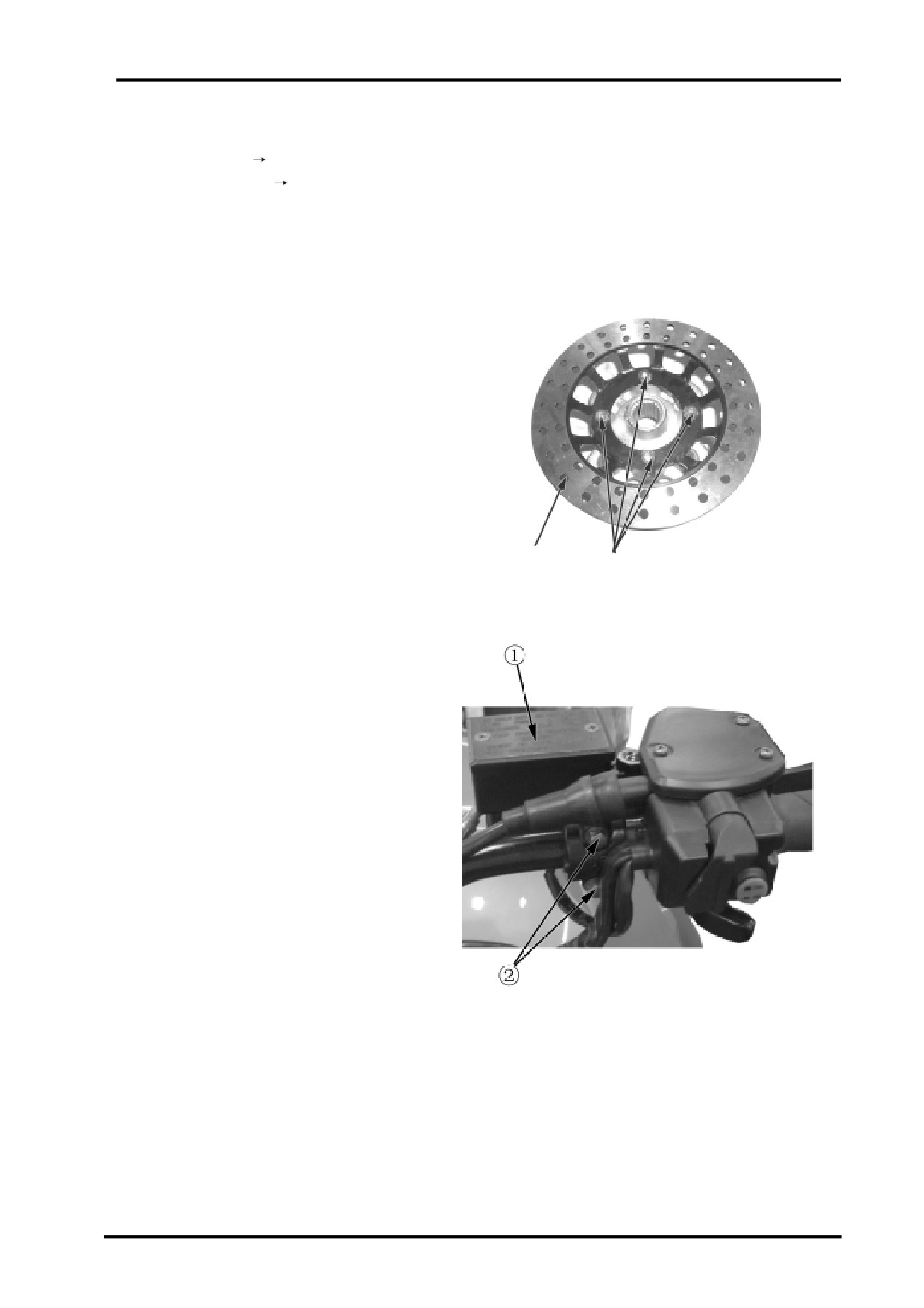
Remove the 4 brake disc bolts shown in the right
picture, then remove brake disc.
Inspection
Thickness of brake disc:
If less than 2.50mm,replace it.
Brake Disc
Bolts
Installation
Reverse the removal procedure for installation.
Tightening torque of brake disc bolts: 25-30N.m
FRONT BRAKE MASTER CYLINDER
Removal
Remove top cover of handlebar;
Remove right hand guard;
Remove bolt no.2;
Seperate master cylinder no.1 of front brake from
handlebar. It’s not necessary to remove it if replace-
ment is not required.
Attention:
Do not hang the master cylinder by brake line,
keep master cylinder in place (not inclined) while
installing it to avoid air entering brake line.
Keep brake line routed properly (refer to Chap-
ter 1) and ensure it is not kinked.
After installation of brake system, check brake
performance.
12-5
4-WHEEL MASTER CYLINDER
Revoval
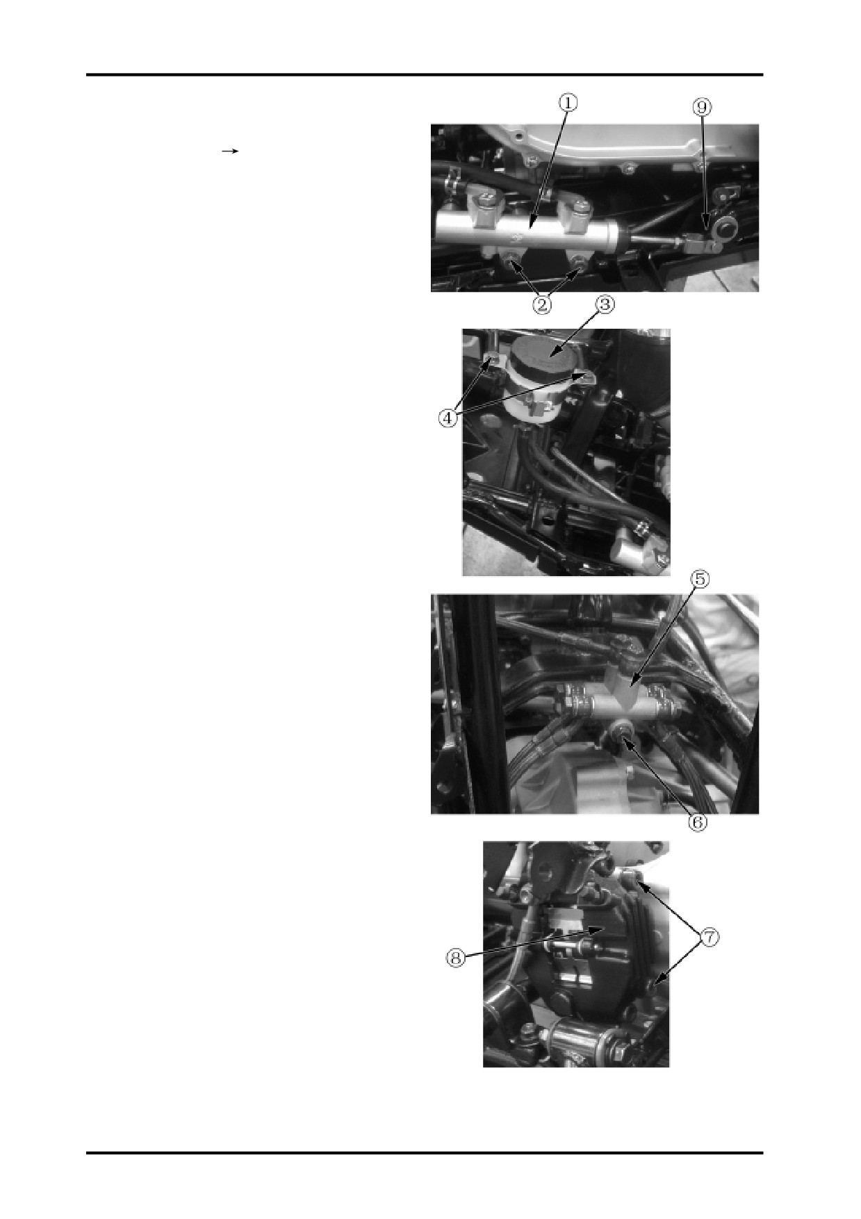
Remove brake pedal (
2-11);
Remove bolts no.2;
Remove bolts no.4;
Remove cotter pin no.9;
Remove master cylinder no.1 from vehicle.
Installation
Reverse the removal procedure for installation.
Attention:
In order to avoid air entering 4-wheel master
cylinder, keep it in place while installing it.
Keep brake line routed properly (refer to Chap-
ter 1) and ensure it is not kinked.
After installation, check brake performance.
T-FITTING
Removal
Remove bolt no.6 and T-fitting.
Installation
Reverse the removal procedure for installation.
Attention: Keep brake line routed properly (refer
to Chapter 1) and ensure it is not kinked.
After installation, check if 4-wheel brake lever or
brake pedal can control front brake.
REAR BRAKE CALIPER
Disassembly
Remove bolt 7 and then disassemble rear brake cali-
per 8
Installation
Reverse the removal procedure for installation.
Attention: Keep brake line routed properly (refer
to Chapter 1) and ensure it is not kinked.
After installation, check if 4-wheel brake lever or
brake pedal can control front brake.
Mainten brake fluid level between “UPPER” and
“LOWER”, if necessary, add DOT 4 fluid (CFMOTO
recommended) into brake fluid reservoir. Check
brake light and switch.
12-6
12 FRONT WHEELS,BRAKE,SUSPENSION,STEERING
FRONT SUSPENSION
Front LH Suspension
ATTENTION:Do not remove left and right suspen-
sion at the same time, otherwise vehicle may tip or
fall.
Removal
Park the vehicle on a level ground and securely sup-
port the front part of vehicle.
Remove LH front protector of suspension (
2-15);
Remove front wheel (
12-3);
Remove brake caliper (
12-4);
Remove front wheel hub (
12-3);
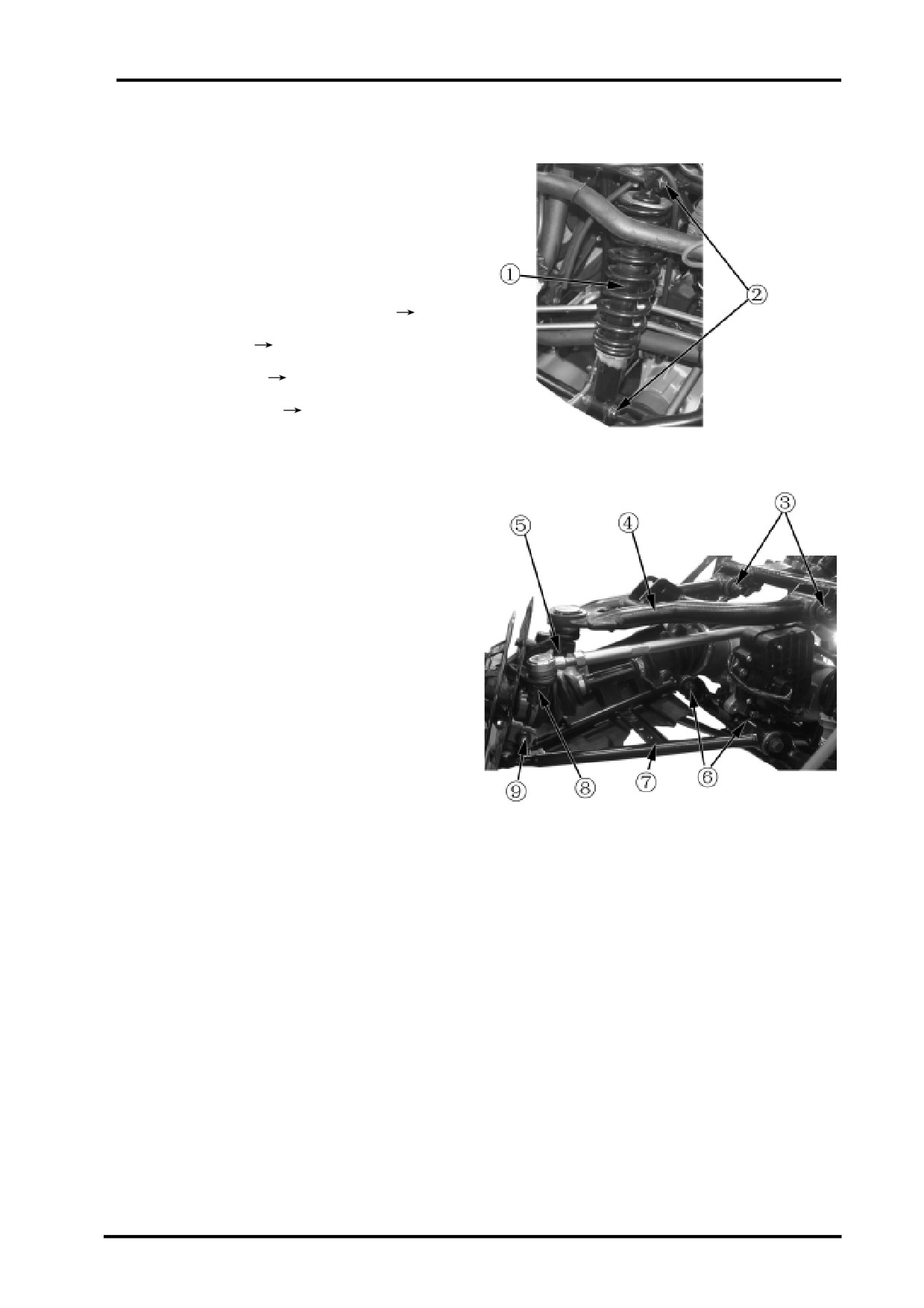
Remove bolts and nuts no.2 of front LH shock ab-
sorber and LH upper A-arm;
Remove front shock absorber no.1;
Remove bolts and nuts no.3 of LH front A-arm;
Remove cotter pin and nut no.5 assembled on left steer-
ing knuckle;
Remove front LH upper A-arm 4;
Remove cotter pin and locking nut no.8 of steering tie-
rod;
Remove bolts and nuts no.6 of LH front A-arm as-
sembled on frame;
Remove locking bolt no.9 of LH front A-arm;
Remove front LH lower A-arm no.7;
Remove steering knuckle from drive shaft;
There are optional shock absorbers available for differ-
ent markets.
The procedure above is for basic configuration. As for
other optional shock absorbers,refer to the procedure
above.
12-7
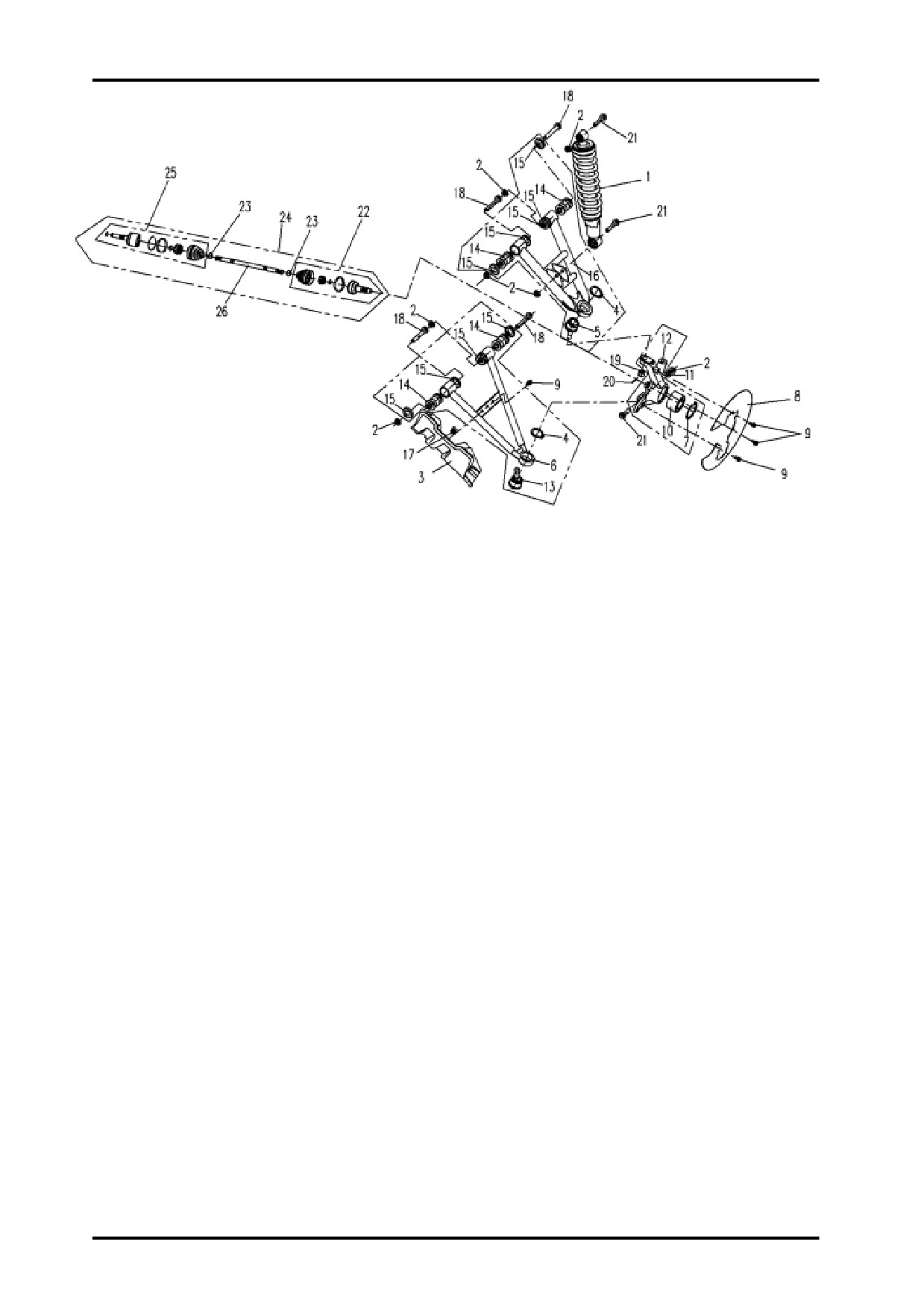
1.Front shock absorber 2.Nut 3. LH protector 4.Circlip
5. Top ball pin 6.LH front lower A-arm 7.Circlip 8.
Guard,brake disc 9.Bolt 10.Hub bearing 11.Washer 12.LH steering knuckle 13. Bottom ball pin 14.Buffering
collar 15.Cap, buffering collar 16.LH front upper A-arm 17.M6 Nut clip 18. Bolt 19. Slot nut 20. Cotter pin 21.
Bolt 22. Bearing kit, fixing end 23. Small clamp 24.Front LH drive shaft assy 25.Bearing kit,motion end 26.
Front LH drive shaft
FRONT SHOCK ABSORBER
Removal
NOTE: If only replacing front shock absorber,it’s not
necessary to remove other parts.
Remove bolt no.21 and nut no.2, then finally remove
front shock absorber (LH) no.1.
Inspection
Check shock absorber for oil leaks,oil seal aging and
other damages.Replace if necessary.
12-8
12 FRONT WHEELS,BRAKE,SUSPENSION,STEERING
Installation
Reverse the removal procedure for installation.
As for removal, installation and check procedure of
front shock absorber (RH),refer to front shock absorber
(LH).
A-ARM
NOTE: There are totally 8 units of A-arm, procedure
of removal, disassembly, check and installation is
same, so only front upper A-arm (LH) and fron lower
A-arm(LH) are introduced.
Front LH A-arm
Removal
Remove front shock absorber(LH) (
12-7);
Remove bolt no.18 and tightening nut no.2 mounting
front LH upper A-arm on frame;
Remove bolt 18 and tightening nut mounting front LH
lower A-arm on fram;
Remove front wheel, brake caliper and wheel hub be-
fore disassembling shock absorber;
Remove steering tie-rod before the removal of bolts;
Remove steering knuckle from drive shaft before re-
moval of front LH A-arm ;
Finally remove front LH A-arm.
12-9
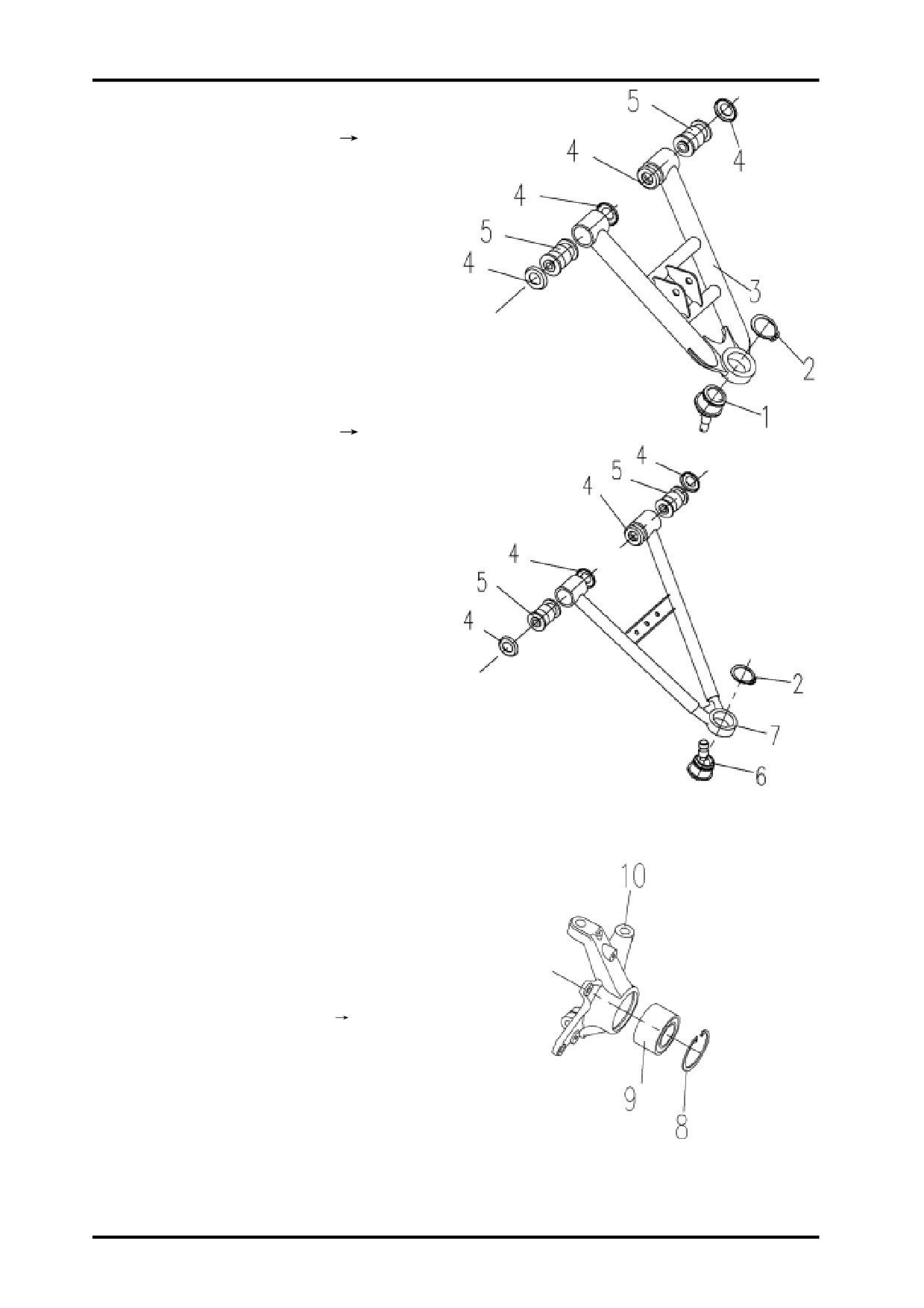
Inspection of upper A-arm
Remove front Upper A-arm (LH) no.3(
12-7);
Remove circlip no.2 (Type: GB894.1 34)
Remove top ball pin no.1;
Check top ball pin no.1 if it can move freely and also
check its clearance. If it cannot move frelly or too big
clearance, replace it. At the same time, check grease
inside top ball pin if it is deteroirated. Check dust boot
of ball pin if damaged or aging;
Remove bushing no.5 of front upper A-arm(LH);
Check bushing no.5 if damaged or aging, replace if
necessary.
Inspection of Lower A-arm
Remove front Lower A-arm (LH) no.3(
12-7);
Remove circlip no.2 (Type: GB894.1 34)
Remove top ball pin no.6;
Check top ball pin no.6 if it can move freely and also
check its clearance. If it cannot move frelly or too big
gap, replace it. At the same time, check grease in-
side top ball pin if it is deteroirated. Check dust boot
of ball pin if damaged or aging.
Remove bushing no.5 of front upper A-arm(LH)
Check bushing no.5 if damaged or aging, replace it if
necessary.
Installation
Use special tool to press ball pin into A-arm;
Install as reverse procedures of disassembly.
Attention: Upper and Lower A-arms should not
vibrate after installation, otherwise replace bush-
ing no.5.
Inspection of Left Steering Knuckle
Remove left steering knuckle no.10 (
12-7);
Remove circlip no.8 (Type: GB893.1 55);
Use special tool to remove hub bearing no.9 (Type:
DAC3055);
Check hub bearing if any damaged and move freely,
or big clearance.Replace it if necessary.
12-10
12 FRONT WHEELS,BRAKE,SUSPENSION,STEERING
DRIVE SHAFT
NOTE:Method and procedure of removal, inspection
and installation between front and rear drive shafts
(LH &RH) are silimar,therefore only front drive shaft
(LH) is introduced.
Front LH Drive Shaft
Removal
NOTE: If only repairing front LH driveshaft, it’s not
necessary to remove front LH suspension from vehicle.
Remove front wheel(LH)(
12-3);
Remove front caliper (LH)(
12-4);
Remove front wheel hub (LH)(
12-3);
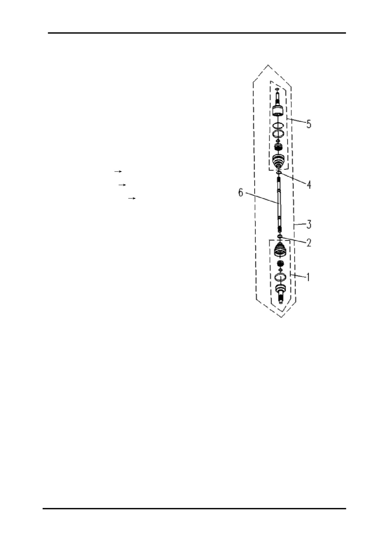
Remove front LH drive shaft no.3 from left side of front
differential;
Check dust boot if any damaged. If damaged, replace
it.
Check bearing kit of fixed and motion end if it can
move flexibly. Also check there is any clearance be-
tween universal joint and splines. If it cannot move
freely and there is noise, replace it.
CAUTION:Universal joint must move freely, oth-
erwise it can damage drive shaft and cause out
of control of tire and accident.
Installation
Reverse the removal procedure for installation.
12-11
STEERING
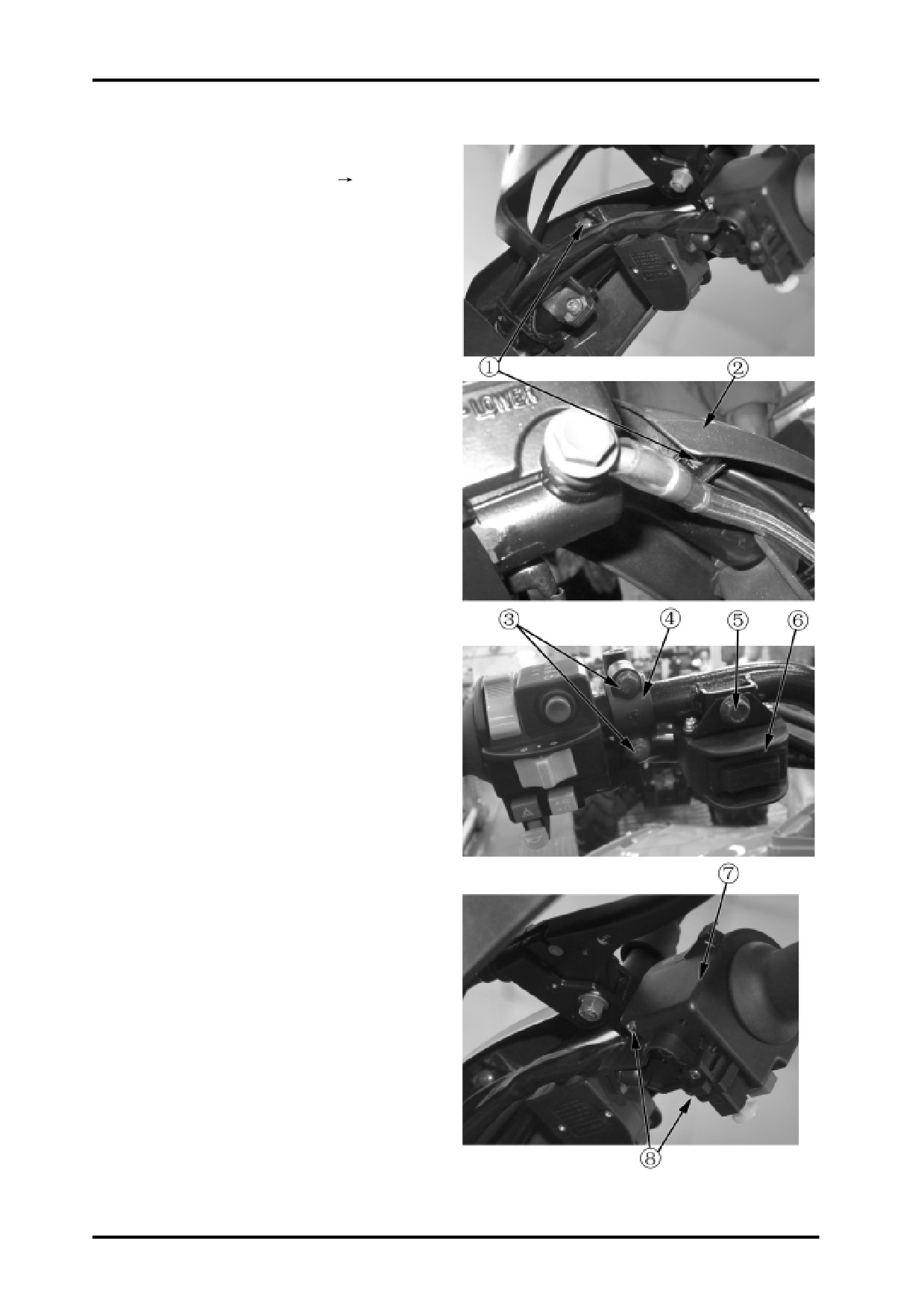
Handlebar
Master cylinderof front brake (
12-15);
Top cover of handlebar
Removal
Remove tapping screw no.1;
Remove top cover of handlebar.
Installation
Reverse the removal procedure for installation.
4-WHEEL HAND BRAKE LEVER
Removal
Remove bolts no.3;
Remove 4-wheel hand brake lever;
Installation
Reverse the removal procedure for installation.
WINCH CONTROL SWITCH
Removal
Remove bolt no.5;
Remove winch control switch no.6.
Installation
Reverse the removal procedure for installation.
LH HANDLEBAR SWITCHES
Removal
Remove bolts no.8;
Remove left handlebar switches no.7.
Installation
Reverse the removal procedure for installation.
12-12
12 FRONT WHEELS,BRAKE,SUSPENSION,STEERING
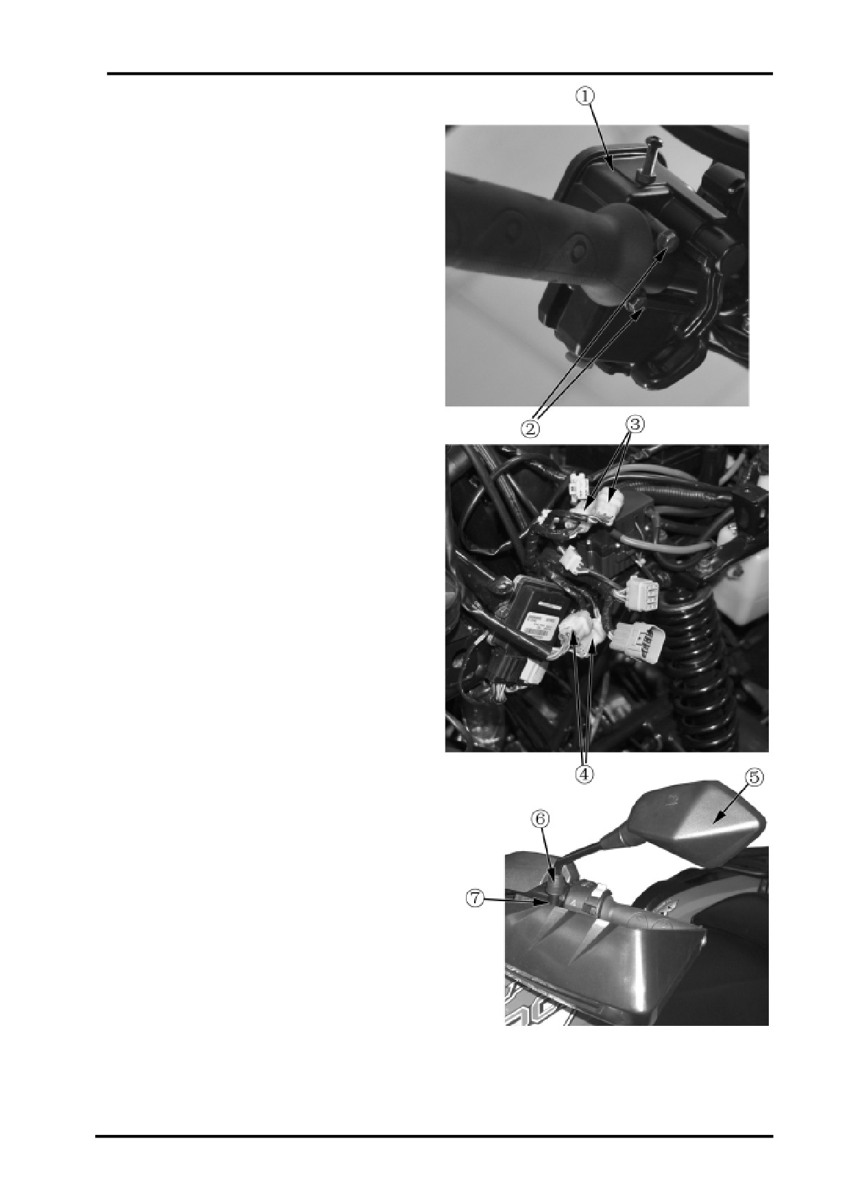
RH HANDLEBAR SWITCHES
Removal
Remove bolts no.2;
Remove right handlebar switches no.1;
Unplug connector no.3 of left handlebar switches,
Unplug connector no.4 of right handlebar switches.
Installation
Reverse the removal procedure for installation.
REAR VIEW MIRROR
Removal
Slide sleeve no.6 out place and unscrew no.nut 7,
then remove rear view mirror no.5 in anti-clockwise
direction.
NOTE: As for rear view mirror (LH), the threads are
right hand, so remove it by turning it counter-clockwise.
Unscrew nut in clockwise direction and unscrew rear
view mirror (RH) to remove.
NOTE: As for rear view mirror (RH),the threads are
left hand, so remove it by turning it counter-clockwise.
Installation
Reverse the removal procedure for installation.
12-13
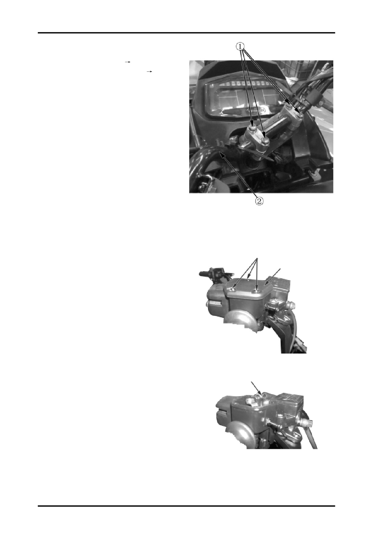
HANDLEBAR
Removal
Remove top cover of handlebar (
12-12);
Remove left and right handlebar switch (
12-12);
Remove left and right brake pump from handlebar;
Remove left and right hand protector;
Remove bolt 1 of handlebar cover;
Remove handlebar no.2.
Installation
Reverse the removal procedure for installation.
Handlebar cover bolt: GB5789 M8x55
Tightening torque: 15-25Nz m (1.5-2.5kgfz m)
ATTENTION:
Keep Main cable, throttle cable, brake line
properly routed.
Screws
RH Handlebar
Cover
Throttle Cable Installation
Remove the 3 screws illustrated in the right picture
and remove top cover of right handlebar;
Install throttle cable;
Install top cover of right handlebar.
Throttle Cable
12-14
12 FRONT WHEELS,BRAKE,SUSPENSION,STEERING
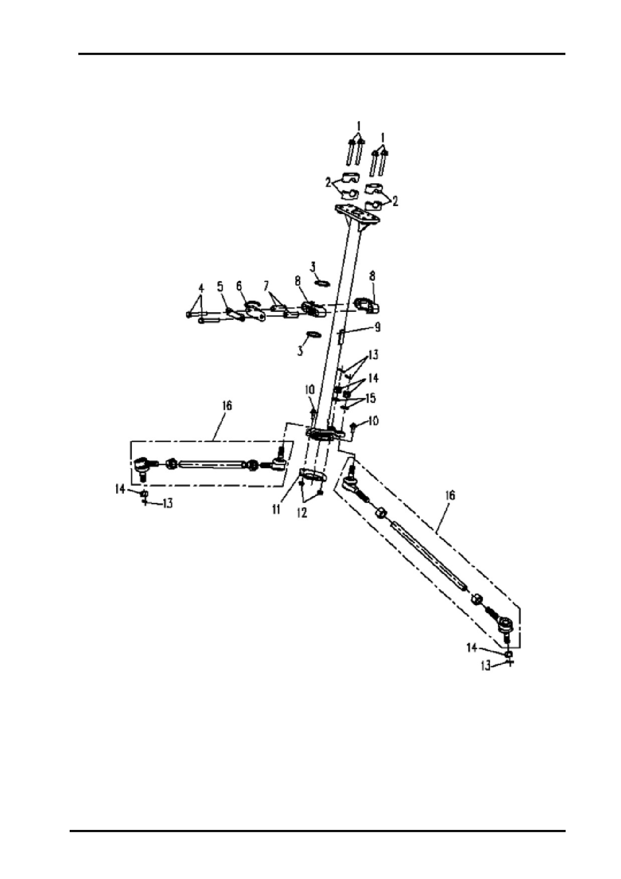
STEERING EXPLODED VIEW
1.Bolt 2.Alum. cover, handlebar 3. Seal ring 4. Bolt 5.Lock clip 6.Adapter plate 7.Bush 8.Support bush,
steering bearing 9.Steering stem 10. Flange bolt M6x17 11. Steering bearing seat 12. Nut 13. Cotter pin
14.Nut 15. Washer 16. Steering tie-rod
12-15
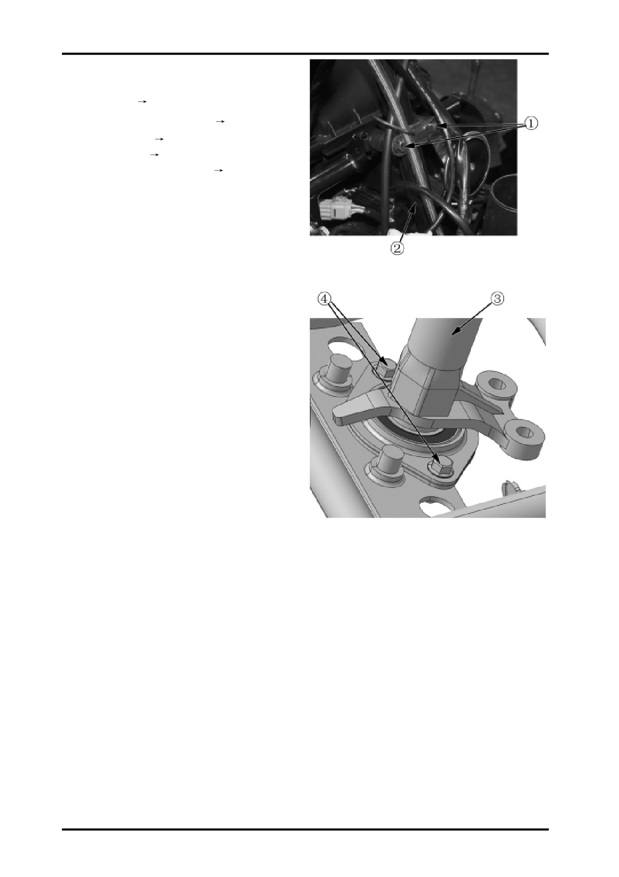
STEERING COLUMN
Removal
Remove plastics( Chapter 2);
Remove upper cover of handlebar (
8-12);
Remove front wheel (
8-2);
Remove handlebar (
8-14);
Remove 4-wheel hand brake lever(
8-12);
Remove connector of handlebar switches;
Remove nut of steering tie-rod and steering column;
Use slotted screw driver and hammer to fix lock clip;
Remove bolt no.1;
Remove cotter pin;
Remove steering tie-rod nut and washer;
Press steering tie-rod away from steering column;
Remove bolt no.14;
Lift steering bearing away from steering stem;
Installation
Reverse the removal procedure for installation.
NOTE: After installation, be sure to check steering
agility.
12-16
12 FRONT WHEELS,BRAKE,SUSPENSION,STEERING
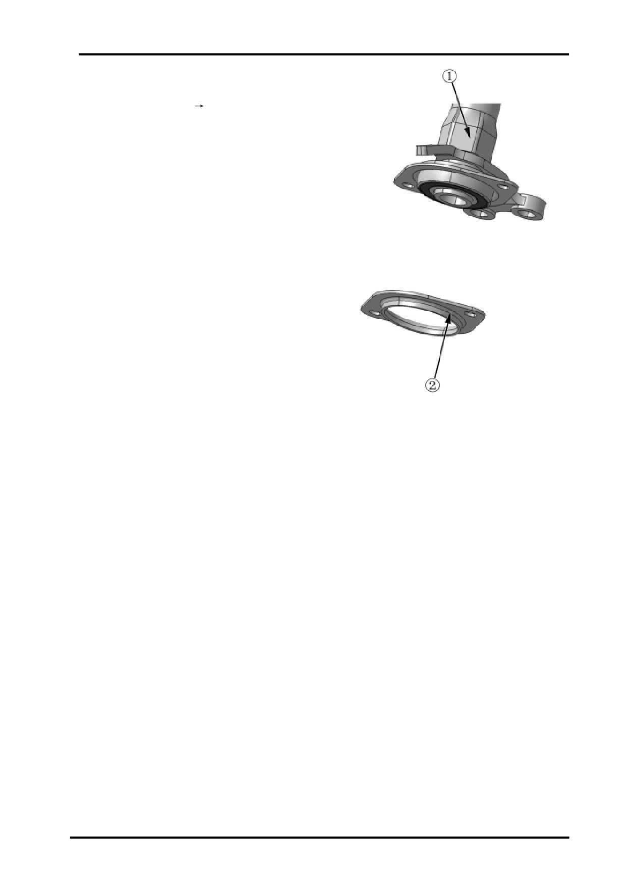
STEERING BEARING & OIL SEAL
Removal
Remove steering bearing (
8-16);
Steering bearing and oil seal are pressed onto steer-
ing column, check if any damaged. If damaged, please
replace it.
Installation
Reverse the removal procedure for installation.
NOTE: After installation, it is necessary to check
steering agility.
12-17
13 REAR WHEELS,BRAKE,SUSPENSION
Maintenance Information
13-1
Rear Brake System
13-4
Troubleshooting
13-2
Rear Suspension
13-5
Rear Wheels
13-3
MAINTENANCE INFORMATION
Operation Cautions
13
CAUTION:
z When performing rim,suspension maintenance,jack or other suitable stand is required to raise the
vehicle body off the ground.
z Rim,suspension mounting bolts,nuts should be genuine parts.
z Never exert an excess force on the wheels.Be careful not to damage wheels.
z when removing tires from wheels,use special tools,such as tire removal rod and tire protector to
avoid damages to rims.
Maintenance Specifications:
Item
Standards
Service Limit
Radia l
-
2.0mm
Wheel Runout
Axial
-
2.0mm
Rear Whee l
Tread Depth
-
3.0mm
Tire
Tire Pressure
45kPa
-
Rear Brake
Brake Lever Free Play
10-20mm
-
Tightening Torque:
Axle Nuts:
110-130N m
Wheel Nuts:
70-80N m
Upper Shock Mounting Bolts&Nuts:
40-50 N m
Lower Shock Mounting Bolts&Nuts:
40-50 N m
13-1
Troubleshooting
Rear wheel runout
Wheel deformation
Defective tire
Tire pressure is excessively low
Wheel is unbalanced
Axle nut is loose
Wheel nuts are loose
Too soft rear shock
Weakened spring tension
Rear shock leak
Too stiff rear shock
Rear shock bending
Too high tire pressure
Poor braking performance
Improperly adjusted braking
Brake pads or disc is damaged or stained
Brake pads is worn
13-2
13 REAR WHEELS,BRAKE,SUSPENSION
REAR WHEEL
Removal
See the front wheel removal.(
12-3)
RIM&CHECK
Check rim for damages,deformation,nicks.If any abnormal condition has been found,replce it.
Slowly turn wheel,use a dial gauge to measure the rim runout
Service Limit:
Radial:2.0mm
Axle:2.0mm
Installation
See front wheel installation(
12-3).
WHEEL HUB
Removal
Remove rear wheel(
13-3);
Remove rear axle nut;
Remove wheel hub.
Installation
Reverse the removal procedure for installation.
Axle Nut Tightening Torque:110-130N m
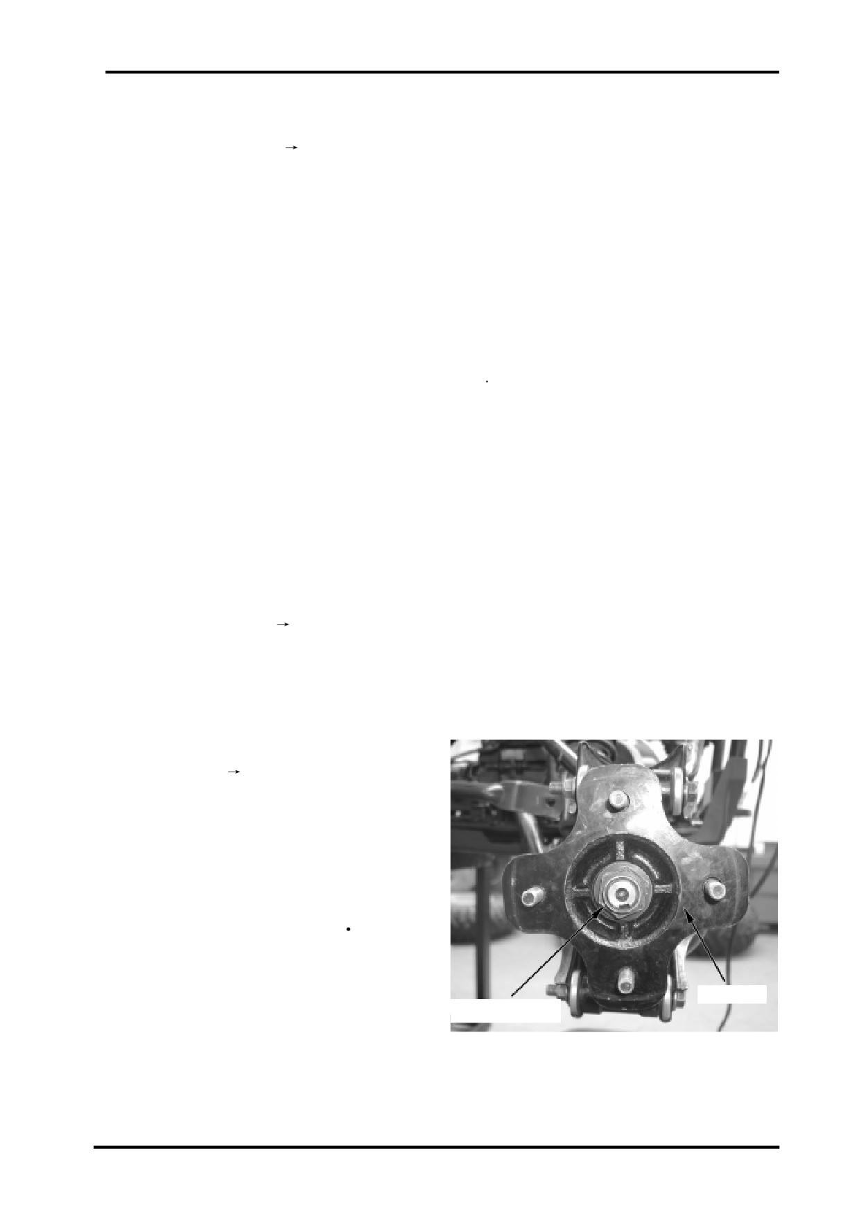
Hub
Axle Nut
13-3
REAR BRAKE SYSTEM
Rear Brake Caliper
Removal
Remove rear wheel,LH(
);
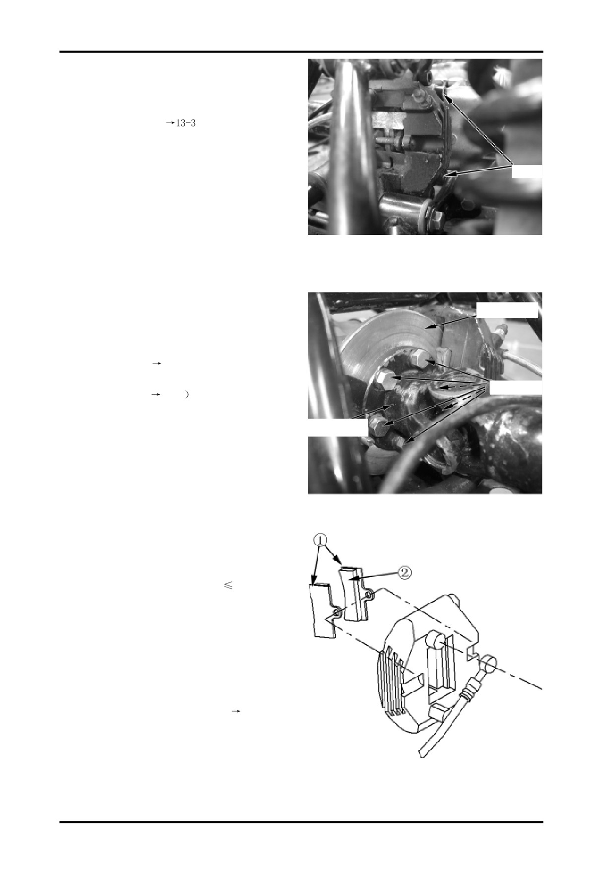
Remove the 2 bolts fitted on A-arm;
Remove brake caliper.
Bolts
Inspection
Visually inspect caliper for cracks and brake fluid leaks.
Replace the part if any damage has been found.
Installation
Reverse the removal procedure for installation.
NOTE:Refer to Chapter 1 for brake line routing.
Rear Brake Disc
Brake Disc
Chapter 1
Remove the drive shaft;
Remove rear caliper(
3-4);
Remove the 6 rear brake disc mounting 6 bolts ;
Bolts
Remove brake disc(
13-3 .
Rear Propshaft
Inspection
Replace the brake disc if it’s thickness is less than 6.
5mm.
Measuring Rear Brake Pads no.1
If the brake pad friction surface no.2
1mm,replace
the 2 brake pads no.1 as an assembly.
Installation
Reverse the removal procedure for installation.
NOTE:Refer to Chapter 1 for brake line routing.
A whole brake system replacement:( Chapter 12,
Brake System)
13-4
13 REAR WHEELS,BRAKE,SUSPENSION
REAR SUSPENSION
Rear Suspension,LH
NOTE:When servicing suspension,don’t remove LH suspension and RH suspension at the same time.
Otherwise,vehicle may tip or fall.
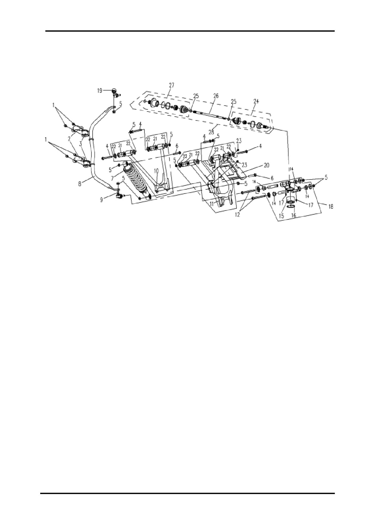
1.Bolts 2.Gland Cover 3.Rubber Support 4.Bolt 5.Self-locking Nut 6.Bolt 7.Rear Shock,LH 8.Stabilizer
Bar 9.Rear LH Ball Pin 10.Real LH A-arm 11.Rear Upper A-arm,LH 12.Rear Lower A-arm,LH 13.Bolt
14.Bushing 15.Bearing 16.Circlip 17.Grease Fittings 18.Bearing Carrier 19.Rear RH Ball Pin 20.Rear LH
Suspension protector 21.Buffering Collar 22.Cap,Buffering Collar 23.Bolt 24.Bearing Kit,Fixed End
25.Small Clamp,Fixed End 26.Rear LH Axle 27.Rear Bell Boot,Motion End,LH 28.Front Axle,LH
Disassembly
STABILIZER BAR
Removal
Remove bolt no.1;Remove gland cover no.2 and rub-
ber support no.3;Remove self-locking nut no.2;Remove
LH ball pin no.9 and RH ball pin no.26;Remove stabi-
lizer bar.
Installation
Reverse the removal procedure for installation.
13-5
REAR LH SHOCK ABSORBER
NOTE When removing LH&RH shock,use appro-
priate tool to support and raise the vehicle body.
If only shock requires maintenance,it’s not necessary
to remove the complete suspension system before
service.
Remove rear LH shock mounting bolt and nut;
Remove rear LH shock.
Installation
Reverse the removal procedure for installation.
REAR A-ARMS,LH
See Front LH Upper/Lower A-arm Removal,
Inspection,Installation in Chapter 8.
REAR SUSPENSION,RH
See rear LH Suspension Removal,Inspection,and
Installation.
13-6
14 FRONT DIFFERENTIAL/REAR GEARCASE
MAINTENANCE INFORMATION
Standards
Lubricating Period
Interval
14
Item
Type
Capacity
Initial
Next
Front Differential
SAE15W/40 SG
Initial:0.33L /Replace:0.28L
350km
5000km
or
Rear Gearcase
SAE80W/90 GL-4
Initial:0.30L/Replace:0.25L
Item
Qty
Specification
Toque(N.m)
Remark
Bolt,F/D
6
M8X28
25
Motor Screw ,F/D
4
M8X20
13
Bolt,Shift Fork Rack Stopper
1
M8X10
13
Apply threadlocker
Nut,F/D
1
M14X1.5
62
Bolt,R/G
6
M10X1.25X22
45
Fill Bolt,F/D
1
M10X1.25X12
25
Drain Bolt,F/D
1
M10X1.25
25
Retainer,F/D
1
M64X1.5X7
80
Bolt,R/G
2
M10X1.25X25
40
Bolt,R/G
6
M8X25
25
Nut,Drive Pinion Gear Shaft,R/G
1
M12X1.25
70
Bolt,Bearing Carrier,R/G
4
M8X30
25
Retainer,R/G
1
M65X1.5X10
70
Nut
1
M8
16
Fill Bolt,R/G
1
M20X1.5X12
25
Drain Bolt,R/G
1
M14X1.25X12
25
F=Front,D=Differential,G=Gearcase,R=Rear
14-1
Inspection & Maintenance
Inspection and maintenance is required if any of problems below happened to front differential and rear gearcase.
Problem Description
Possible Causes
1.A pronounced hesitation or “jerky” movement during
A.Bearing damage;
acceleration,deceleration,or sustained speed.
B.Improper gear lash;
C.Gear severely worn;
2. Abnormal noise in front differential and/or rear
D.Gear blocked
gearcase.
E.Drive shaft broken
F.lack of lubrication
3.No power transmitted from the engine to the front and/
G.Foreiggn objects in the front differential and/or rear
or rear wheel.
gearcase
NOTE: Problems A,B and C above may be difficult to diagnose.The symptoms are quite subtle and
difficult to distinguish from normal machine operating noise.If there is reason to believe these components
are damaged,remove the components and inspect them.
Obsernvation and Judgement
1.Investigate any unusual noises:
a. Unstable noise during acceleration or deceleration.The noise increases with front and/or rear
wheel speed,but it does not increase with higher engine or transmission speed.
Diagnosis:Possible wheel bearing damage.
b. Constant abnormal noise during acceleration or deceleration might be caused by improper gear lash
during assembly.
NOTE:Improper assembly or adjustment of the front differential and/or rear gearcase will aggravate gear
wear and block;
c.Slight noise would be noticed during low-speed driving, while may not be heard during high-speed driving.
This symptom might be caused by gear block.
WARNING:In case of above mentioned itmes, stop riding immediately for inspection and fix the
problem before successive use.otherwise it will cause loss of control of the machine and possible
injury to the rider.
2.Check lubrication condition;
Often check if the consumption of lubricant is normal and the metal particles in lubricant is normal.
3.Chcek lubricant leakage;
a.Check front differential and rear gearcase housing for oil residue throughly;
b.Oil residue on ground on the parking lot;
c.Lubricant splash inspection.Check if there is gear case or oil seal leakage. Replace broken parts if
necessary.
14-2
14 FRONT DIFFERENTIAL/REAR GEARCASE
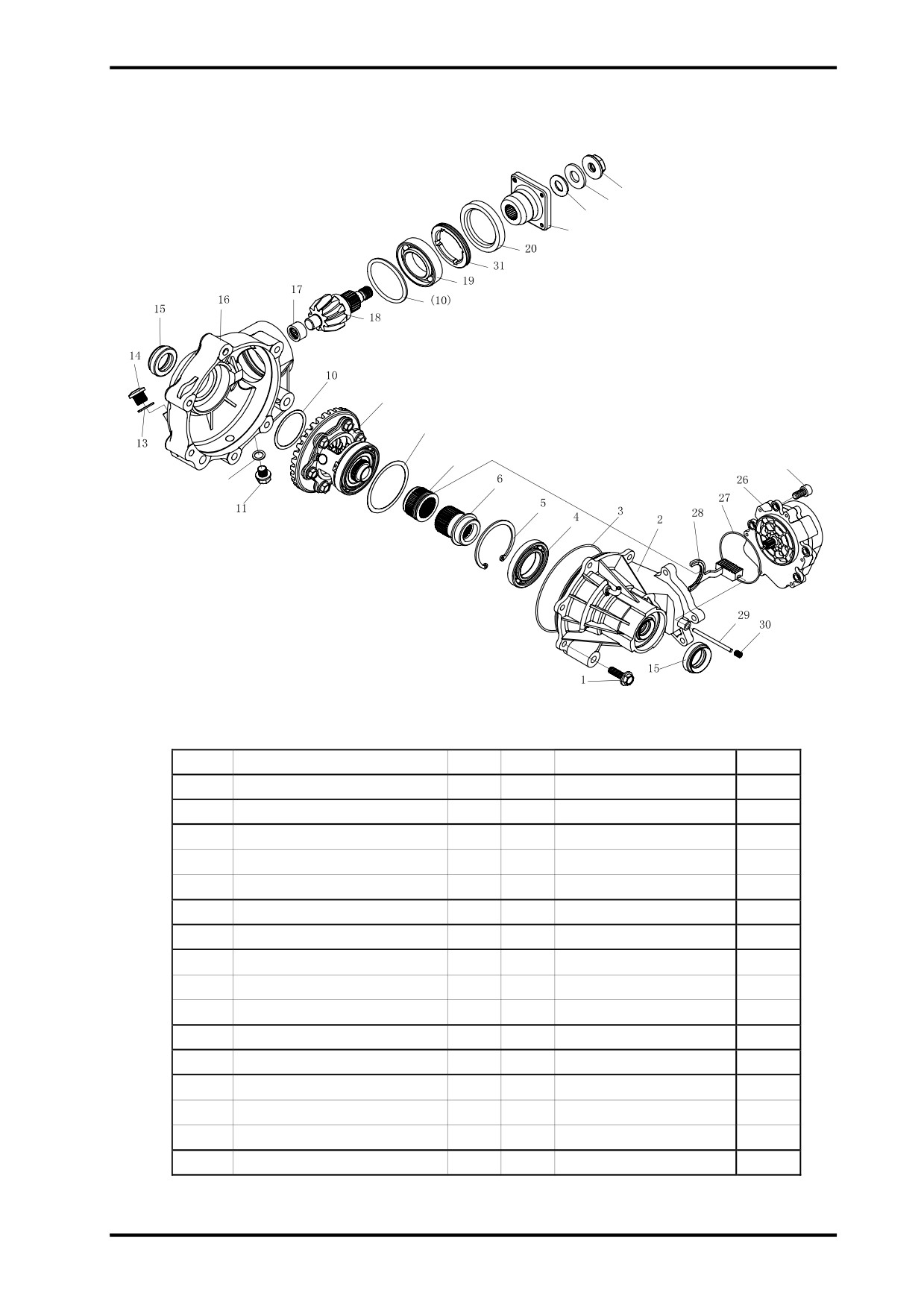
FRONT DIFFERENTIAL EXPLODED VIEW
24
23
22
21
9
8
7
25
12
Item
Part Name
QTY
Item
Part Name
QTY
1
Bolt M8X28
6
17
Bearing F1512
1
2
Differential Gear Case,LH
1
18
Drive Pinion Gear
1
3
O-ring 141X2.4
1
19
Bearing 6007
1
4
Bearing 16007
1
20
Oil Seal 48X65X9
1
5
Circlip 62
1
21
Coupler
1
6
Drive Clutch Cover
1
22
O-ring 14X6.8
1
7
Drive Clutch
1
23
Nut Washer
1
8
Shimφ83X71
1-2
24
Nut M14X1.5
1
9
Differential Gear Assembly
1
25
Screw M8X20
4
10
Shim φ61X48
2-4
26
Gear Motor
1
11
Drain Bolt M10X1.25
1
27
O-ring 81.2X1.9
1
12
Washer 10,Drain Bolt
1
28
Shift Fork Rack
1
13
Washer 14,Fill Bolt
1
29
Stopper Shaft
1
14
Bolt M14X1.25
1
30
Screw M8X10
1
15
Oil Seal 24X38X8
2
31
Retainer M64x1.5X7
1
16
Differential Gear Case,RH
1
32
14-3
Inspection After Front Differential Disassembly
Check if there is damage or cracks on the front diffrential gear case and the condition of bearing seats.
Replace if necessary.
Check front differential bearing free play,rotation,bearing cage,steel balls,needles conditions. Replace if
necessary(Using special tools).
Check if oil seal lips and O-ring shape are normal. Replace if necessary.
Check cylndrical surface that contacts oil seal lips condition.Replace if necessary.
Check teeth of front differential drive pinion gear and ring gear. Replace if necessary.
Check differential spider gears teeth,gear carrier for wears. Replace if necessary.
Check differential inside and outside splines for wears. Replace if necessary.
Check rack face, inspect worn surface. Replace broken parts if necessary.
Check gear motor working status. Replace with new parts if necessary.
Gear motor inspection must be carried out with special equipment or acted on the vehicle.
Check other parts. Replace broken parts if necessary.
14-4
14 FRONT DIFFERENTIAL/REAR GEARCASE
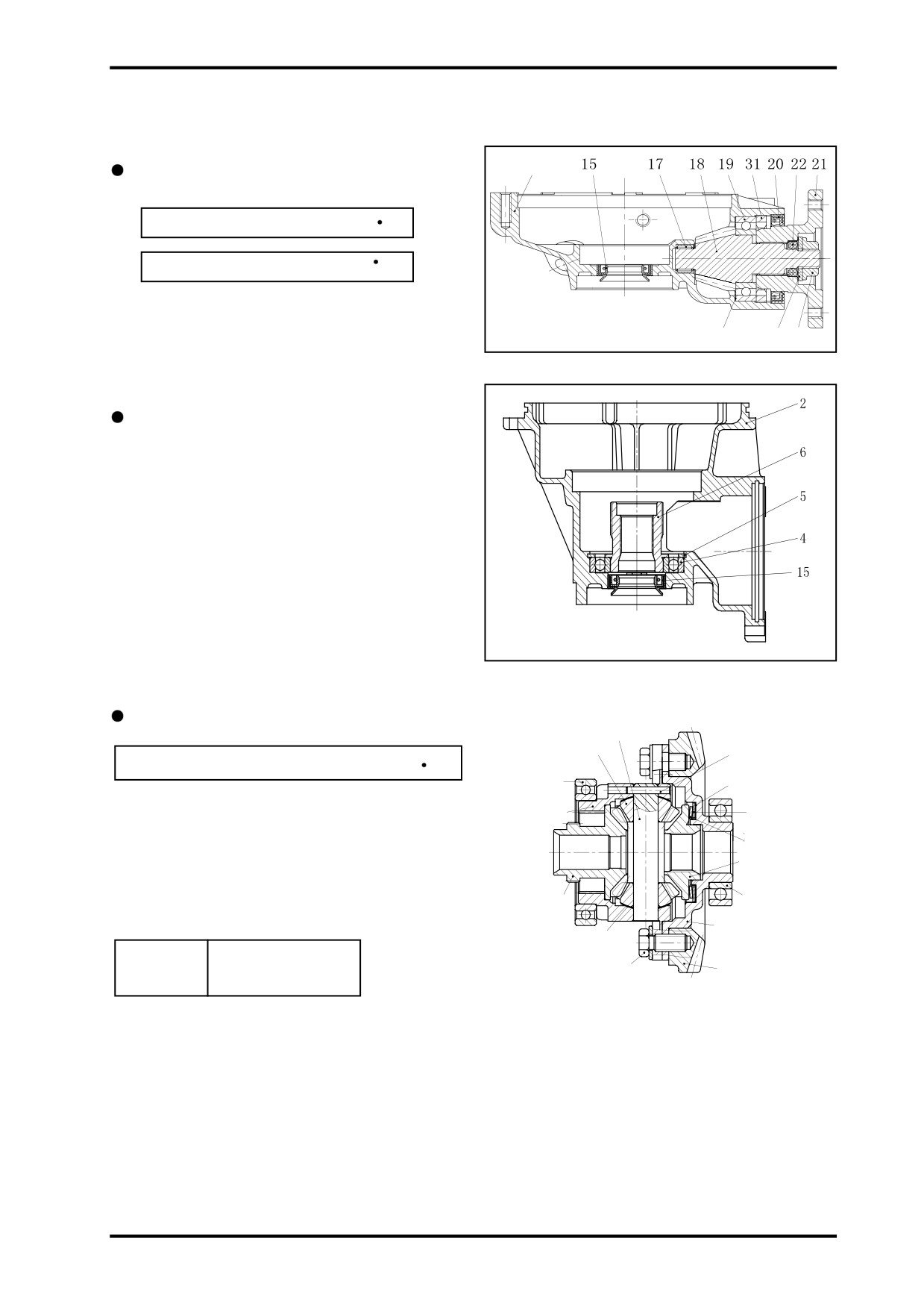
Front Differential Assembly and Adjust-
ment
16
Front RH Differential Gear Case Assembly
Item “31” tightening torque: 80N m
Item “24” tightening torque 62N m
NOTE: Apply engine oil on oil seal, bearing and drive
clutch assembly;
10
23 24
Apply threadlocker on item “24” .
Front LH Differential Gear Case Assembly
NOTE:Use engine oil for oil seal or bearing
assembly.
Differential Gear Assembly
Spider Gear Pin
Spider Gear
Locking Pin
Bolt M10 X 1.25 X 22 tightening torque 45N m
Bearing 61912
Adjustment Shim
Gear Carrier
Washer
NOTE: Use engine oil for bearing and differential gear;
Use proper shim to make gear work freely;
Washer
Driven Gear
Drive Gear
Bearing 6007
Upper Gear Carrier
Washer
Shim
0.1 0.2 0.3 0.4
Bolt M10X1.25X22
Ring Gear
thickness
0.5 1.0
14-5
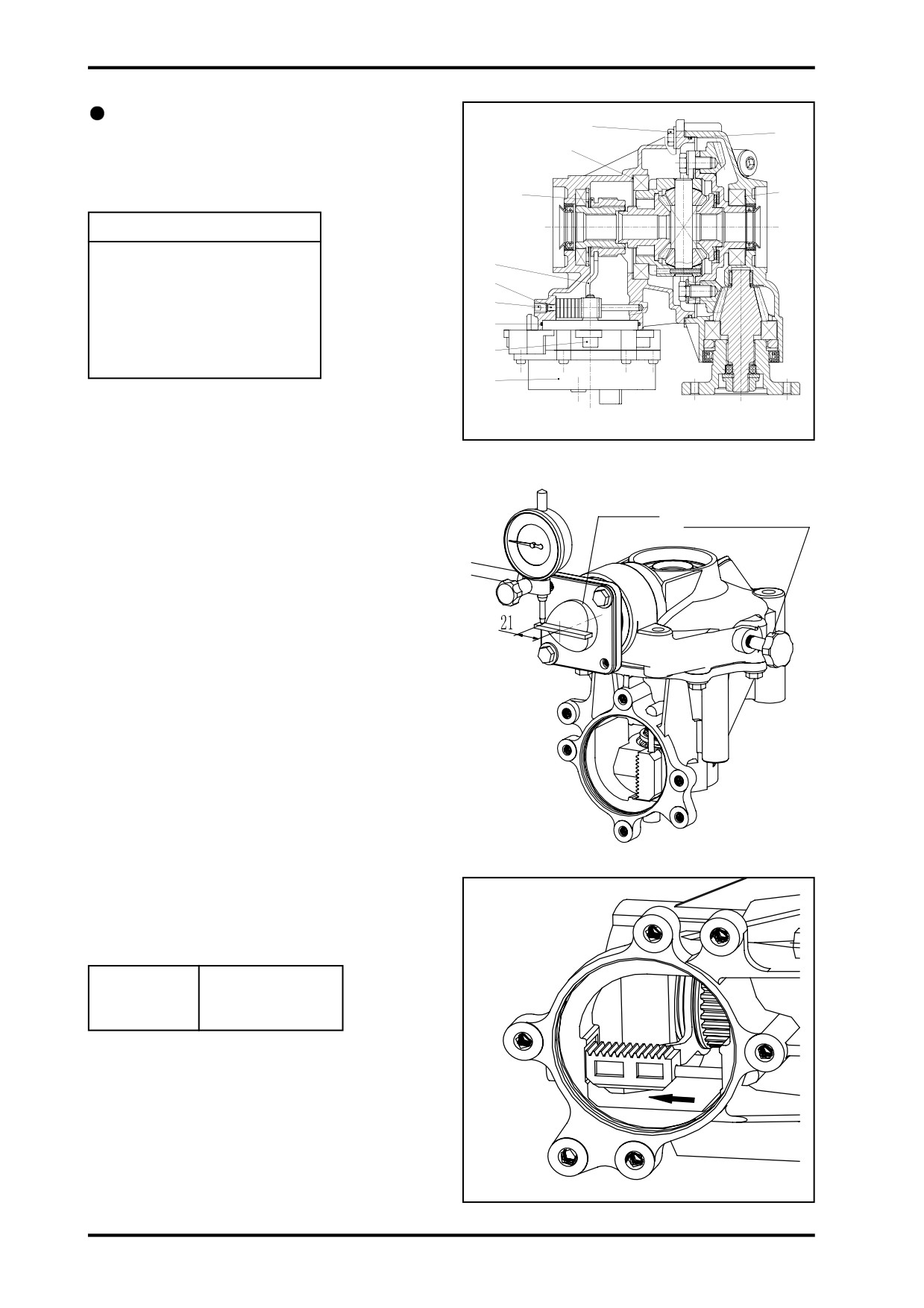
Front Differential Assembly and Adjustment
1
3
8
Assemble front differential as illustrated:
7
10
Tightening Torque
Item “1”
25Nz m
28
29
Item “25”
13Nz m
30
Item “30”
13Nz m
27
Fill Bolt
25Nz m
25
Drain Bolt
25Nz m
26
Use threadlocker for item “30” assembly.
a Use proper shim no.8 and no.10 to adjust gear lash
between drive pinion gear and ring gear.
1
2
Measure the lash between drive bevel gear and driven
bevel gear as inllutrated: Install gear lash measure-
ment tool no.1,locking bolt(M10X1.25X60) no.2.Using
a dial gauge, make sure the measuring point is 21mm
(0.83 in).Rotate gear lash measurement tool from en-
gagement to engagement.
Standard: 0.10 ~ 0.25
Shim
0.1 0.2 0.3 0.4
thickness
0.5
1.0
b When assembling front differential gear motor,shift
fork rack and drive clutch should be against tightly as
the arrow points.
14-6
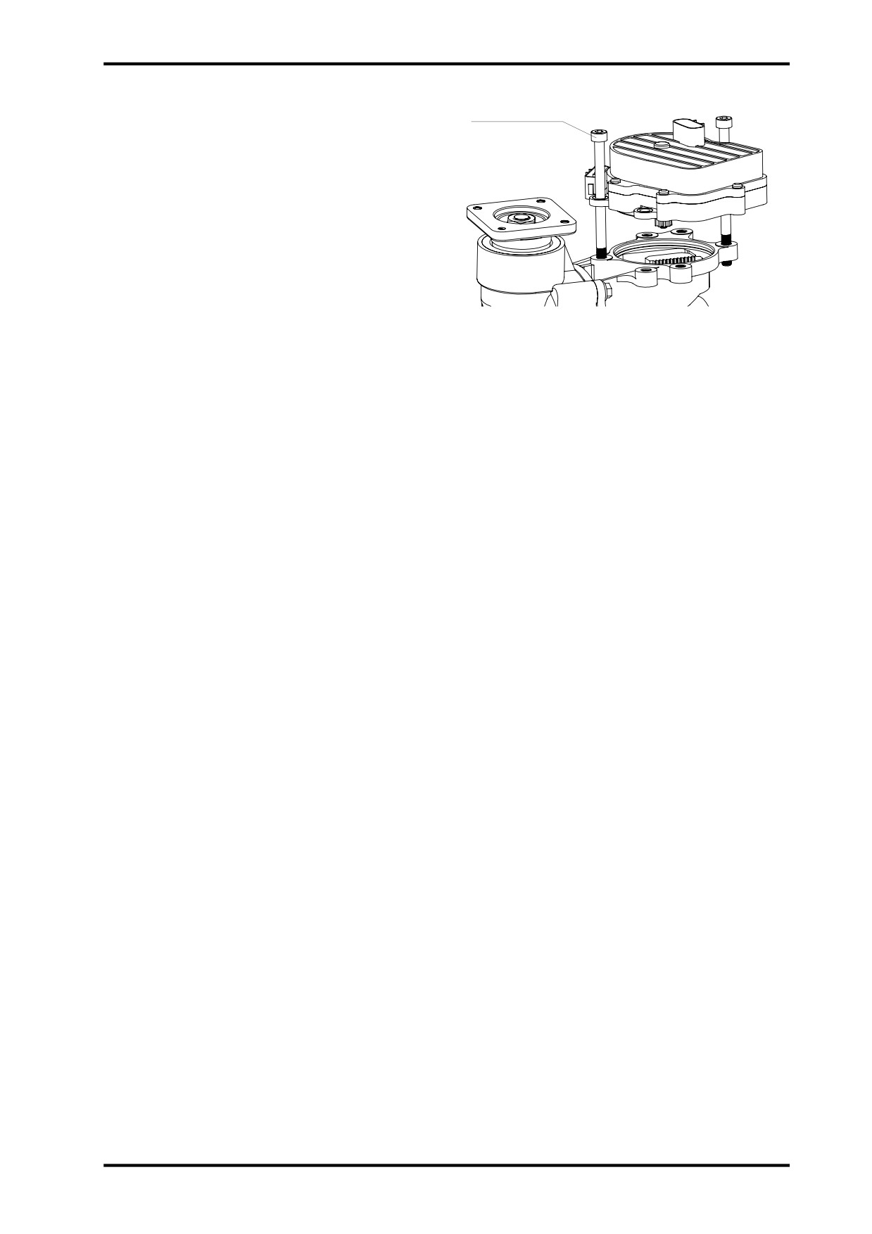
14 FRONT DIFFERENTIAL/REAR GEARCASE
c Using special equipment or vehicle control circuit,
1
switch diff. motor to 2WD before assembly.
d Make sure b and c is assembled properly and use
illustrated position screw M8X100 no.1 to assemble
differential gear motor and front differential.
14-7
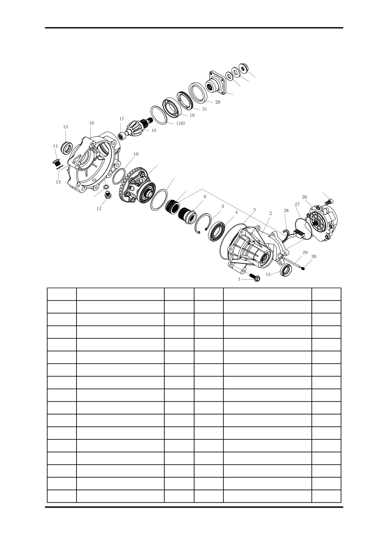
14 FRONT DIFFERENTIAL/REAR GEARCASE
FRONT DIFFERENTIAL EXPLODED VIEW
24
23
22
21
9
8
7
25
12
Ite m
P/N
Qty
Item
P/N
Qty
1
Bolt M8X28
6
17
Bearing F1512
1
2
Differential Gear Case,LH
1
18
Drive Pinion Gear
1
3
O-ring 141X24
1
19
Bearing 6007
1
4
Bearing 16007
1
20
Oil Seal 48X65X9
1
5
Circlip 62
1
21
Coupler
1
6
Driver Clutch Cover
1
22
O-ring 14X6.8
1
7
Driver Clutch
1
23
Nut Washer
1
8
Shim
83X71
1-2
24
Nut M14X1.5
1
9
Differential Gear Assy
1
25
Screw M8X20
4
10
Shim
61X48
2-4
26
Gear Motor
1
11
Drain Bolt M10X1.25
1
27
O-ring 81.2X1.9
1
12
Washer 10,Drain Bolt
1
28
Shift Fork Rack
1
13
Washer 14,Fill Bolt
1
29
Stopper Shaft
1
14
Bolt M14X1.25
1
30
Screw M8X10
1
15
Oil Seal 24X38X8
2
31
Retainer M64X1.5X7
1
16
Differential Gear Case,RH
1
32
14-3
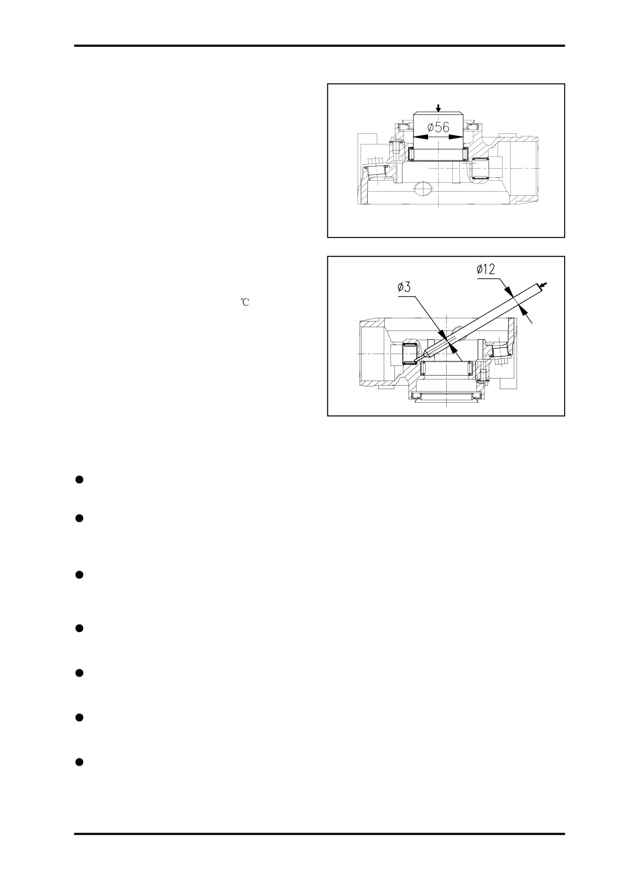
14 FRONT DIFFERENTIAL/REAR GEARCASE
Bearing Disassembly
a Disassemble needle bearing 55BTM6720 as shown
when necessary.
b When replacing needle bearing NA5903, rear
gearcase should be heated to 150
before
replacement.
Rear Gearcase Inspection after Disas-
sembly
Check if there is damage or cracks on the rear gear case and the condition of bearing seats.Replace if
necessary.
Check rear gearcase bearing free play,rotation,bearing cage,steel balls,needles conditions. Replace if
necessary(Using special tools).
Check teeth of gearcase drive pinion gear and ring gear. Replace if necessary.
Check if oil seal lips and O-ring shape are normal. Replace if necessary.
Check cylndrical surface that contacts oil seal lips.Replace if necessary.
Check gearcase inside and outside splines for wears. Replace if necessary.
Check other parts. Replace if necessary.
14-9
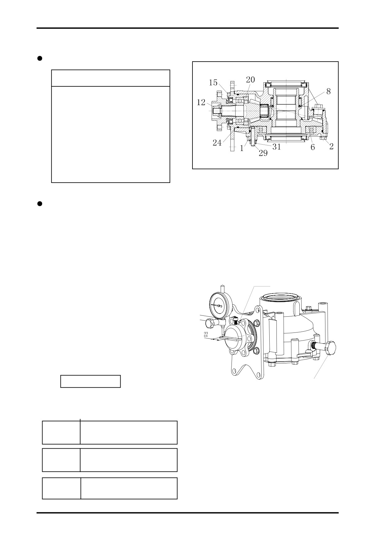
Rear Gearcase Assembly and Adjustment
Illustration
Tightening Torque
Item “1”
40Nz m
Item “2”
25Nz m
Item “12”
70Nz m
Item “15”
25Nz m
Item “20”
70Nz m
Item “31”
16Nz m
Bolt
25Nz m
Bolt
25Nz m
Use threadlocker for Item “29” assembly.
Assembly and gear lash adjustment between drive
pinion gear and ring gear of rear gearcase.
a Adjust installation gear lash by choosing “24”washer.
b Adjust gear lash by choosing “6” washer.
c Check tooth contact between drive pinion gear and
1
ring gear by coloring.
d Measure installation gear lash between drive pinion
gear and ring gear as illustrated: Install gear lash
measurement tool no.1,locking bolt(M14X1.25X60) no.
2.Using a dial gauge,make sure the measuring point
is 22mm.Turn gear lash measurement tool from en-
gagement to engagement.
Standard: 0.1~0.2
2
e Keep the axial gear lash within 0.1~0.2 by choosing
washer “8” .
Washer
0.2 0.3 0.4
“6”
Washer
1.0 1.2 1.4 1.6 1.8
“8”
Washer
0.4 0.5 0.6
“24”
14-10