CFMoto motorcycle CF650NK. Service Manual - part 26
9-36 CRANKSHAFT/TRANSMISSION
Transmission
Transmission Shaft Disassembly
●
Remove the transmission assy (see Transmission
Assy Removal).
●
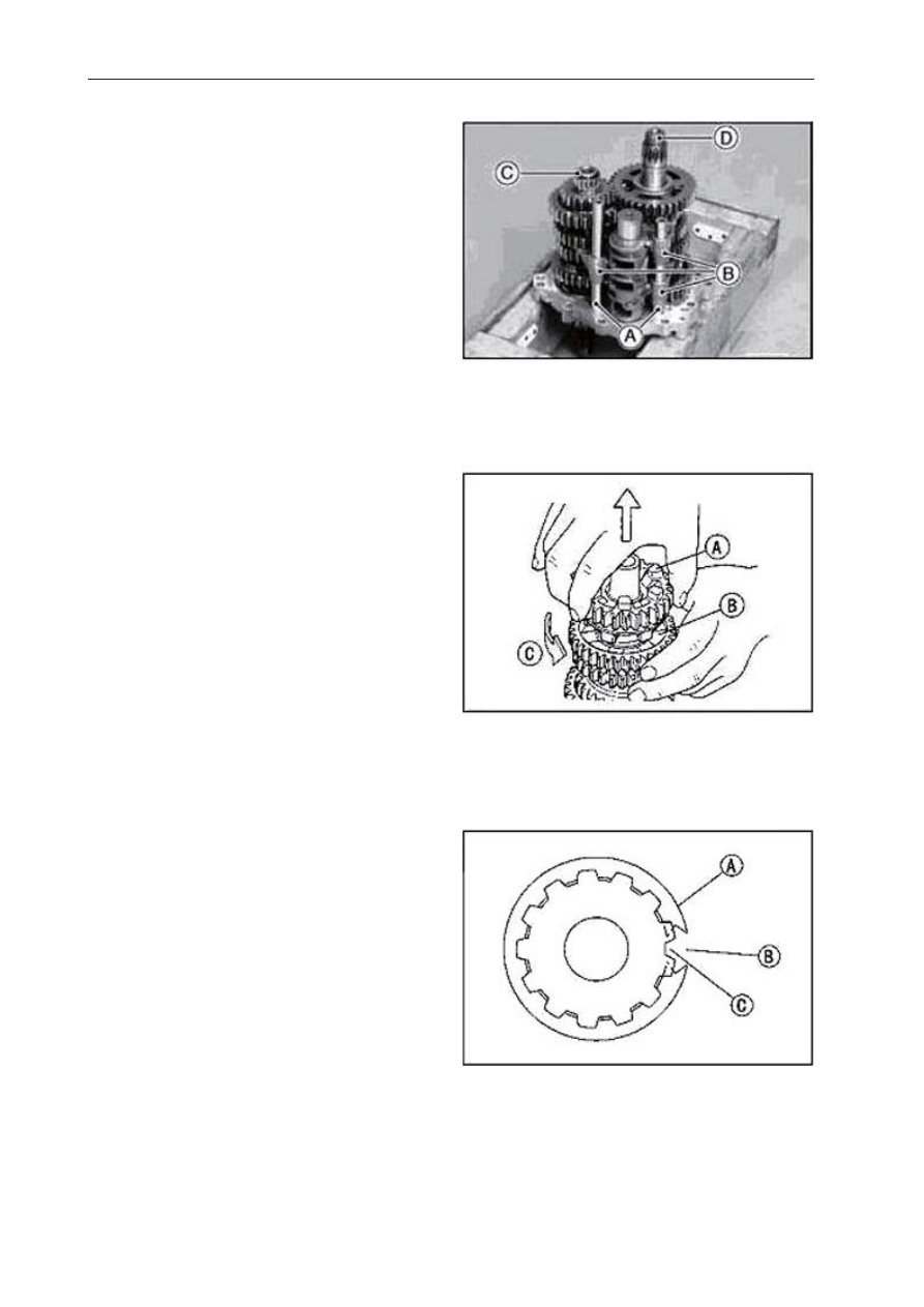
Remove:
Shift Rods [A]
Shift Forks [B]
Drive Shaft [C] and Output Shaft [D]
●
R e m o v e t h e c i r c l i p s , d i s a s s e m b l e t h e
transmission shafts.
●
Remove the
fi
fth 5th gear.
Transmission Shaft Assembly
●
Apply engine oil to the collar, needle bearing
and the shaft.
●
Install the collar to the shaft.
●
Replace all the removed circlips.
●
Install the circlips [A] so that the opening [B] is
aligned with a spline groove [C].