CFMoto motorcycle CF650NK. Service Manual - part 11
 

  Index      Manuals     CFMoto motorcycle CF650NK. Service Manual


Search            copyright infringement  


Content      ..     9      10      11      12     ..


CFMoto motorcycle CF650NK. Service Manual - part 11


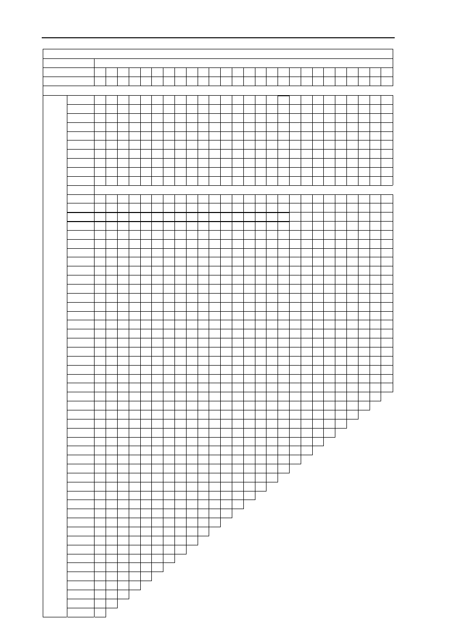
Valve Clearance Adjustment(Exhaust Valve) 


                                  Present Shim                                         Example                                            

Mark 

320 322  324 326 328 

330 332 334 

336 338 340 342 344 346 348 350 352 354 356 358  360 362 364 

366 368

370

Thickness 

3.2  3.22  3.24 3.26 3.28  3.3  3.32 3.34 3.36 3.38 3.4 3.42 3.44 3.46 3.48 3.5 3.52 3.54 3.56 3.58  3.6  3.62 3.64  3.66 3.68 3.7


0

0.01 

— — 

— —

—  — — — 

— 3.2 3.22 3.24 3.26 3.28 3.3 3.32 3.34 3.36 3.38  3.4  3.42  3.44  3.46  3.48 3.5

0.02

0.03  — — 

— —

—  — — — 

— 3.2 3.22 3.24 3.26 3.28 3.3 3.32 3.34 3.36 3.38 3.4  3.42  3.44  3.46  3.48  3.5 3.52

0.04

0.05  — — 

— —

—  — — — 

3.2 3.22 3.24 3.26 3.28 3.3 3.32 3.34 3.36 3.38 3.4 3.42  3.44  3.46  3.48  3.5  3.52 3.54

0.06

0.07  — — 

— —

—  — — 

3.2  3.22 3.24 3.26 3.28 3.3 3.32 3.34 3.36 3.38 3.4 3.42 3.44  3.46  3.48  3.5  3.52  3.54 3.56

0.08

0.09  —  — — 

— — 

3.2  3.22 3.24 3.26 3.28 3.3 3.32 3.34 3.36 3.38 3.4 3.42 3.44 3.46  3.48  3.5  3.52  3.54  3.56 3.58

0.10

0.11  —  —  —  —

—  3.2  3.22 3.24 3.26 3.28 3.3 3.32 3.34 3.36 3.38 3.4 3.42 3.44 3.46 3.48  3.5  3.52 3.54  3.56 3.58 3.6

0.12

0.13  —  —  —  — 3.2  3.22 3.24 3.26 3.28 3.3 3.32 3.34 3.36 3.38 3.4 3.42 3.44 3.46 3.48 3.5  3.52 3.54 3.56  3.58  3.6 3.62

0.14

0.15  —  —  —  3.2 3.22  3.24 3.26 3.28

3.3 3.32 3.34 3.36 3.38 3.4 3.42 3.44 3.46 3.48 3.5 3.52  3.54 3.56 3.58  3.6  3.62 3.64

0.16

0.17 


  3.2  3.22 3.24  3.26 3.28  3.3  3.32 3.34 3.36 3.38 3.4 3.42 3.44 3.46 3.48 3.5 3.52 3.54  3.56 3.58  3.6  3.62 3.64 3.66

0.18

0.19  —  3.2  3.22  3.24  3.26  3.28 3.3 3.32

3.34 3.36 3.38 3.4 3.42 3.44 3.46 3.48 3.5 3.52 3.54 3.56  3.58 3.6 3.62 

3.64  3.66 3.68

0.20

0.26 

Specified Clearance/No Change Required 

0.27

0.28  3.26 3.28  3.3  3.32 3.34  3.36 3.38  3.4  3.42 3.44 3.46 3.48 3.5 3.52 3.54 3.56 3.58 3.6 3.62 3.64  3.66 3.68  3.7  3.72 3.74 3.76

0.29

0.30  3.28 3.3  3.32  3.34  3.36  3.38 3.4 3.42

3.44 3.46 3.48 3.5 3.52 3.54 3.56 3.58 3.6 3.62 3.64 3.66  3.68 3.7 3.72 

3.74  3.76 3.78

0.31

0.32  3.3  3.32  3.34 3.36 3.38  3.4  3.42 3.44 3.46 3.48 3.5 3.52 3.54 3.56 3.58 3.6 3.62 3.64 3.66 3.68  3.7  3.72 3.74  3.76 3.78 3.8

0.33

0.34  3.32 3.34  3.36 3.38  3.4  3.42 3.44 3.46 3.48 3.5 3.52 3.54 3.56 3.58 3.6 3.62 3.64 3.66 3.68 3.7  3.72 3.74 3.76  3.78  3.8 3.82

0.35

0.36  3.34 3.36  3.38  3.4 3.42  3.44 3.46 3.48

3.5 3.52 3.54 3.56 3.58 3.6 3.62 3.64 3.66 3.68 3.7 3.72  3.74 3.76 3.78  3.8  3.82 3.84

0.37

0.38  3.36 3.38  3.4  3.42 3.44  3.46 3.48  3.5  3.52 3.54 3.56 3.58 3.6 3.62 3.64 3.66 3.68 3.7 3.72 3.74  3.76 3.78  3.8  3.82 3.84 3.86

0.39

0.40  3.38 3.4  3.42  3.44  3.46  3.48 3.5 3.52

3.54 3.56 3.58 3.6 3.62 3.64 3.66 3.68 3.7 3.72 3.74 3.76  3.78 3.8 3.82 

3.84  3.86 3.88

0.41

0.42  3.4  3.42  3.44 3.46 3.48  3.5  3.52 3.54 3.56 3.58 3.6 3.62 3.64 3.66 3.68 3.7 3.72 3.74 3.76 3.78  3.8  3.82 3.84  3.86 3.88 3.9

0.43

0.44  3.42 3.44  3.46 3.48  3.5  3.52 3.54 3.56 3.58 3.6 3.62 3.64 3.66 3.68 3.7 3.72 3.74 3.76 3.78 3.8  3.82 3.84 3.86  3.88  3.9 3.92

0.45

0.46  3.44 3.46  3.48  3.5 3.52  3.54 3.56 3.58

3.6 3.62 3.64 3.66 3.68 3.7 3.72 3.74 3.76 3.78 3.8 3.82  3.84 3.86 3.88  3.9  3.92 3.94

0.47

0.48  3.46 3.48  3.5  3.52 3.54  3.56 3.58  3.6  3.62 3.64 3.66 3.68 3.7 3.72 3.74 3.76 3.78 3.8 3.82 3.84  3.86 3.88  3.9  3.92 3.94 3.96

0.49

0.50  3.48 3.5  3.52  3.54  3.56  3.58 3.6 3.62

3.64 3.66 3.68 3.7 3.72 3.74 3.76 3.78 3.8 3.82 3.84 3.86  3.88 3.9 3.92 

3.94  3.96 3.98

0.51

0.52  3.5  3.52  3.54 3.56 3.58  3.6  3.62 3.64 3.66 3.68 3.7 3.72 3.74 3.76 3.78 3.8 3.82 3.84 3.86 3.88  3.9  3.92 3.94  3.96 3.98

4

0.53

0.54  3.52 3.54  3.56 3.58  3.6  3.62 3.64 3.66 3.68 3.7 3.72 3.74 3.76 3.78 3.8 3.82 3.84 3.86 3.88 3.9  3.92 3.94 3.96  3.98  4 4.02

0.55

0.56  3.54 3.56  3.58  3.6 3.62  3.64 3.66 3.68

3.7 3.72 3.74 3.76 3.78 3.8 3.82 3.84 3.86 3.88 3.9 3.92  3.94 3.96 3.98 

4  4.02 4.04

0.57

0.58  3.56 3.58  3.6  3.62 3.64  3.66 3.68  3.7  3.72 3.74 3.76 3.78 3.8 3.82 3.84 3.86 3.88 3.9 3.92 3.94  3.96 3.98  4  4.02 4.04 4.06

0.59

0.60  3.58  3.6  3.62 3.64 3.66  3.68  3.7  3.72 3.74 3.76 3.78 3.8 3.82 3.84 3.86 3.88 3.9 3.92 3.94 3.96  3.98  4  4.02  4.04 4.06 4.08

0.61

0.62  3.6  3.62  3.64 3.66 3.68  3.7  3.72 3.74 3.76 3.78 3.8 3.82 3.84 3.86 3.88 3.9 3.92 3.94 3.96 3.98  4  4.02 4.04  4.06 4.08 4.1

0.63

0.64  3.62 3.64  3.66 3.68  3.7  3.72 3.74 3.76 3.78 3.8 3.82 3.84 3.86 3.88 3.9 3.92 3.94 3.96 3.98 4  4.02 4.04 4.06  4.08  4.1 4.12

0.65

0.66  3.64 3.66  3.68  3.7 3.72  3.74 3.76 3.78

3.8 3.82 3.84 3.86 3.88 3.9 3.92 3.94 3.96 3.98 4 4.02  4.04 4.06 4.08  4.1  4.12 4.14

0.67

0.68  3.66 3.68  3.7  3.72 3.74  3.76 3.78  3.8  3.82 3.84 3.86 3.88 3.9 3.92 3.94 3.96 3.98 4 4.02 4.04  4.06 4.08  4.1  4.12 4.14 4.16

0.69

0.70  3.68 3.7  3.72  3.74  3.76  3.78 3.8 3.82

3.84 3.86 3.88 3.9 3.92 3.94 3.96 3.98 4 4.02 4.04 4.06  4.08 4.1 4.12 

4.14  4.16 4.18

0.71

0.72  3.7  3.72  3.74 3.76 3.78  3.8  3.82 3.84 3.86 3.88 3.9 3.92 3.94 3.96 3.98 4 4.02 4.04 4.06 4.08  4.1  4.12 4.14  4.16 4.18


0.73

0.74  3.72 3.74  3.76 3.78  3.8  3.82 3.84 3.86 3.88 3.9 3.92 3.94 3.96 3.98 4 4.02 4.04 4.06 4.08 4.1  4.12 4.14 4.16  4.18   


0.75

0.76  3.74 3.76  3.78  3.8 3.82  3.84 3.86 3.88

3.9 3.92 3.94 3.96 3.98 4 4.02 4.04 4.06 4.08 4.1 4.12  4.14 4.16 4.18 


0.77

0.78  3.76 3.78  3.8  3.82 3.84  3.86 3.88  3.9  3.92 3.94 3.96 3.98 4 4.02 4.04 4.06 4.08 4.1 4.12 4.14  4.16 4.18 


0.79

0.80  3.78  3.8  3.82 3.84 3.86  3.88  3.9  3.92 3.94 3.96 3.98 4 4.02 4.04 4.06 4.08 4.1 4.12 4.14 4.16  4.18   


0.81

0.82  3.8  3.82  3.84 3.86 3.88  3.9  3.92 3.94 3.96 3.98 4 4.02 4.04 4.06 4.08 4.1 4.12 4.14 4.16 4.18   


0.83

0.84  3.82 3.84  3.86 3.88  3.9  3.92 3.94 3.96 3.98 4 4.02 4.04 4.06 4.08 4.1 4.12 4.14 4.16 4.18


0.85

0.86  3.84  3.86 3.88  3.9 3.92 3.94  3.96  3.98 4 4.02 4.04 4.06 4.08 4.1 4.12 4.14 4.16 4.18


0.87

0.88  3.86 3.88  3.9  3.92 3.94  3.96 3.98  4  4.02 4.04 4.06 4.08 4.1 4.12 4.14 4.16 4.18


0.89

0.90  3.88  3.9  3.92 3.94 3.96  3.98  4  4.02 4.04 4.06 4.08 4.1 4.12 4.14 4.16 4.18


0.91

0.92  3.9  3.92  3.94 3.96 3.98 

4  4.02 4.04 4.06 4.08 4.1 4.12 4.14 4.16 4.18


0.93

0.94  3.92 3.94  3.96 3.98  4  4.02 4.04 4.06 4.08 4.1 4.12 4.14 4.16 4.18


0.95

0.96  3.94  3.96  3.98  4 4.02  4.04  4.06  4.08 4.1 4.12 4.14 4.16 4.18


0.97

0.98  3.96  3.98  4  4.02  4.04  4.06  4.08  4.1  4.12 4.14 4.16 4.18


0.99

1.00  3.98  4  4.02  4.04  4.06  4.08  4.1  4.12 4.14 4.16 4.18


1.01

1.02  4  4.02  4.04  4.06  4.08  4.1  4.12  4.14 4.16 4.18


1.03

1.04  4.02  4.04  4.06  4.08  4.1  4.12  4.14  4.16 4.18


1.05

1.06  4.04  4.06  4.08  4.1 4.12  4.14  4.16  4.18


1.07

1.08  4.06  4.08  4.1  4.12  4.14  4.16  4.18    


1.09

1.10  4.08  4.1  4.12  4.14  4.16  4.18    


1.11

1.12  4.1  4.12  4.14  4.16  4.18     


1.13

1.14  4.12  4.14  4.16  4.18   


1.15

1.16  4.14  4.16  4.18    


1.17

1.18  4.16  4.18     


Example 


     Clear

ance

 Measur

em

ent 

1.19

1.20  4.18   


 PERIODIC MAINTENANCE 2-23

-------------------------------------------------------------------------------------------------------------------------------------------------------------

Valve Clearance Adjustment Exhaust Valve(Continued)

Present Shim                                 

Mark

372

374

376

378

380

382

384

386

388

390

392

394

396

398 400 402 404 406 408 410 412 414 416

418

Thickness

3.72 3.74 3.76 3.78

3.8

3.82 3.84 3.86 3.88

3.9

3.92 3.94 3.96 3.98

4

4.02 4.04 4.06 4.08 4.1 4.12 4.14 4.16 4.18

Clearance Measurement

0

~

0.01

3.52 3.54 3.56 3.58

3.6

3.62 3.64 3.66 3.68

3.7

3.72 3.74 3.76 3.78 3.8 3.82 3.84 3.86 3.88 3.9 3.92 3.94 3.96 3.98

0.02

~

0.03

3.54 3.56 3.58

3.6

3.62 3.64 3.66 3.68

3.7

3.72 3.74 3.76 3.78

3.8 3.82 3.84 3.86 3.88 3.9 3.92 3.94 3.96 3.98

4

0.04

~

0.05

3.56 3.58

3.6

3.62 3.64 3.66 3.68

3.7

3.72 3.74 3.76 3.78

3.8

3.82 3.84 3.86 3.88 3.9 3.92 3.94 3.96 3.98

4

4.02

0.06

~

0.07

3.58

3.6

3.62 3.64 3.66 3.68

3.7

3.72 3.74 3.76 3.78

3.8

3.82 3.84 3.86 3.88 3.9 3.92 3.94 3.96 3.98

4

4.02 4.04

0.08

~

0.09

3.6

3.62 3.64 3.66 3.68

3.7

3.72 3.74 3.76 3.78

3.8

3.82 3.84 3.86 3.88 3.9 3.92 3.94 3.96 3.98

4

4.02 4.04 4.06

0.10

~

0.11

3.62 3.64 3.66 3.68

3.7

3.72 3.74 3.76 3.78

3.8

3.82 3.84 3.86 3.88 3.9 3.92 3.94 3.96 3.98

4

4.02 4.04 4.06 4.08

0.12

~

0.13

3.64 3.66 3.68

3.7

3.72 3.74 3.76 3.78

3.8

3.82 3.84 3.86 3.88

3.9 3.92 3.94 3.96 3.98

4

4.02 4.04 4.06 4.08

4.1

0.14

~

0.15

3.66 3.68

3.7

3.72 3.74 3.76 3.78

3.8

3.82 3.84 3.86 3.88

3.9

3.92 3.94 3.96 3.98

4

4.02 4.04 4.06 4.08 4.1

4.12

0.16

~

0.17

3.68

3.7

3.72 3.74 3.76 3.78

3.8

3.82 3.84 3.86 3.88

3.9

3.92 3.94 3.96 3.98

4

4.02 4.04 4.06 4.08 4.1 4.12 4.14

0.18

~

0.19

3.7

3.72 3.74 3.76 3.78

3.8

3.82 3.84 3.86 3.88

3.9

3.92 3.94 3.96 3.98

4

4.02 4.04 4.06 4.08 4.1 4.12 4.14 4.16

0.20

~

0.26

Speci

fi

 ed Clearance/No Change Required

0.27

~

0.28

3.78

3.8

3.82 3.84 3.86 3.88

3.9

3.92 3.94 3.96 3.98

4

4.02 4.04 4.06 4.08 4.1 4.12 4.14 4.16 4.18

0.29

~

0.30

3.8

3.82 3.84 3.86 3.88

3.9

3.92 3.94 3.96 3.98

4

4.02 4.04 4.06 4.08 4.1 4.12 4.14 4.16 4.18

0.31

`

0.32

3.82 3.84 3.86 3.88

3.9

3.92 3.94 3.96 3.98

4

4.02 4.04 4.06 4.08 4.1 4.12 4.14 4.16 4.18

0.33

~

0.34

3.84 3.86 3.88

3.9

3.92 3.94 3.96 3.98

4

4.02 4.04 4.06 4.08

4.1 4.12 4.14 4.16 4.18

0.35

~

0.36

3.86 3.88

3.9

3.92 3.94 3.96 3.98

4

4.02 4.04 4.06 4.08

4.1

4.12 4.14 4.16 4.18

0.37

~

0.38

3.88

3.9

3.92 3.94 3.96 3.98

4

4.02 4.04 4.06 4.08

4.1

4.12 4.14 4.16 4.18

0.39

~

0.40

3.9

3.92 3.94 3.96 3.98

4

4.02 4.04 4.06 4.08

4.1

4.12 4.14 4.16 4.18

0.41

~

0.42

3.92 3.94 3.96 3.98

4

4.02 4.04 4.06 4.08

4.1

4.12 4.14 4.16 4.18

0.43

~

0.44

3.94 3.96 3.98

4

4.02 4.04 4.06 4.08

4.1

4.12 4.14 4.16 4.18

0.45

~

0.46

3.96 3.98

4

4.02 4.04 4.06 4.08

4.1

4.12 4.14 4.16 4.18

0.47

~

0.48

3.98

4

4.02 4.04 4.06 4.08

4.1

4.12 4.14 4.16 4.18

0.49

~

0.50

4

4.02 4.04 4.06 4.08

4.1

4.12 4.14 4.16 4.18

0.51

~

0.52

4.02 4.04 4.06 4.08

4.1

4.12 4.14 4.16 4.18

0.53

~

0.54

4.04 4.06 4.08

4.1

4.12 4.14 4.16 4.18

0.55

~

0.56

4.06 4.08

4.1

4.12 4.14 4.16 4.18

0.57

~

0.58

4.08

4.1

4.12 4.14 4.16 4.18

0.59

~

0.60

4.1

4.12 4.14 4.16 4.18

0.61

~

0.62

4.12 4.14 4.16 4.18

0.63

~

0.64

4.14 4.16 4.18

0.65

~

0.66

4.16 4.18

0.67

~

0.68

4.18

2-24 PERIODIC MAINTENANCE 

-------------------------------------------------------------------------------------------------------------------------------------------------------------

PERIODIC MAINTENANCE 2-25

Clutch

Clutch Operation Inspection

 Pull the clutch lever just enough to take up the

   free play [A].

 Measure the gap between the lever and the lever

   holder.

If the gap is too wide,the clutch may not release

   fully. If the gap is too narrow, the clutch may not
   engage fully. In either case, adjust it.

  Clutch Lever Free Play

     Standard: 2~3 mm (0.08~0.12 in.)

WARNING

To avoid a serious burn,never tough the en-

gine or exhaust pipe during clutch adjustment.

 Turn the adjuster [A] so that 5~6mm (0.20~0.24

   in.) [B] of threads are visible.

 Slide the dust cover [A] at the middle of the clutch

   cable out of place.

 Loosen the locknut [B] at the middle of clutch

   cable.

 Turn the adjustment nut [C] until the free play is

  correct.

WARNING

Be sure that the outer cable end at the clutch lever

is fully seated in the adjuster at the clutch lever,or it

could slip into place later,creating enough cable

play to prevent clutch disengagement.

 After the adjustment, tighten the locknut and start

   the engine and check that the clutch does not slip
   and that it releases properly.

Wheels/Tires

Air Pressure Inspection

 Remove the air valve cap.

 Measure the tire air pressure with an air pressure

   gauge [A] when the tires are cold (that is,when
   the motorcycle has not been ridden more than a
   mile during the past 3 hours).

 Install the air valve cap.

 Adjust the tire pressure according to the specifica-

   tions if necessary.

Air Pressure (when cold)

     Front:   280 kPa (2.80 kgf/cm

2

, 39.8 psi)

     Rear:    280 kPa (2.80 kgf/cm

2

, 39.8 psi)

!

!

-------------------------------------------------------------------------------------------------------------------------------------------------------------

2-26  PERIODIC MAINTENANCE

Wheel/Tire Damage Inspection

 Remove any imbedded stones [A] or other foreign

  particles [B] from tread.

 Visually inspect the tire for cracks and cuts, and

   replace the tire if necessary. Swelling or high
   spots indicate internal damage, requiring tire
   replacement.

 Visually inspect the wheel for cracks, cuts and

   dents damage.

If any damage is found, replace the wheel if

   necessary.

Tire Tread Wear, Abnormal Wear Inspection

O

 As the tire tread wears down, the tire becomes

   more susceptible to puncture and failure. An
   accepted estimate is that 90% of all tire failures
   occur during the last 10% of tread life (90% worn).
   So it is false economy and unsafe to use the tires
   until they are bald.

 Measure the tread depth at the center of the tread

   with a depth gauge [A]. Since the tire may wear
   unevenly,take measurement at several places.

If any measurement is less than the service limit,

   replace the tire (see Tire Removal/Installation in
   the Wheels/Tires chapter).

Tread Depth

   Standard:

       Front:     4.5 mm (0.18 in.)

       Rear:      5.5 mm (0.22 in.)

   Service Limit:

       Front:     0.8~1.0 mm (0.03~0.04 in.)

       Rear:      0.8~1.0 mm (0.03~0.04 in.)

WARNING

To ensure safe handling and stability,use only

the recommended standard tires for

replacement,inflated to the standard pressure.

WARNING

NOTE

O


Most countries may have their own regulations a

   minimum tire tread depth:be sure to follow them.

O


Check and balance the wheel when a tire is

   replaced with a new one.

!

-------------------------------------------------------------------------------------------------------------------------------------------------------------

PERIODIC MAINTENANCE 2-27

Wheel Bearing Damage Inspection

 Raise the front wheel off the ground with jack (see

   Front Wheel Removal in the Wheels/Tires chapter).

 Turn the handlebar all the way to the right or left.

 Inspect the roughness of the front wheel bearing

   by pushing and pulling [A] the wheel.

 Spin [B] the front wheel lightly, and check for

   smoothly turn, roughness, binding or noise.

If roughness, binding or noise is found, remove the

   front wheel and inspect the wheel bearing (see
   Front Wheel Removal, Hub Bearing Inspection in
   the Wheels/Tires chapter).

 Raise the rear wheel off the ground with stand

   (see Rear Wheel Removal in the Wheels/Tires
   chapter).

 Inspect the roughness of the rear wheel bearing

   by pushing and pulling [A] the wheel.

 Spin [B] the rear wheel lightly, and check for

   smoothly turn, roughness,binding or noise.

If roughness, binding or noise is found, remove the

   rear wheel and inspect the wheel bearing (see
   Rear Wheel Removal, Hub Bearing Inspection in
   the Wheels/Tire chapter) and coupling (see Cou-
   pling Bearing Inspection in the Final Drive chapter).

Drive Train

Drive Chain Lubrication Condition Inspection

 If a special lubricant is not available, a heavy oil

   such as SAE 90 is preferred to a lighter oil be
   cause it will stay on the chain longer and provide
   better lubrication.

 If the chain appears especially dirty, clean it

   before lubrication.

N

O

I

T

U

A

C

The O-rings between the side plates seal in

the lubricant between the pin and the

bushing. To avoid damaging the O-ring and

resultant loss of lubricant,observe the follow-

ing rules. Use only kerosene or diesel oil for

cleaning and O-ring drive chain. Any other

cleaning solution such as gasoline or trichlo-

roethylene will cause deterioration and

swelling of the O-ring. Immediately blow the

chain dry with compressed air after cleaning.

Complete cleaning and drying the chain

within 10 minutes.

-------------------------------------------------------------------------------------------------------------------------------------------------------------

2-28  PERIODIC MAINTENANCE

 Apply oil to the sides of the rollers so that oil will

  penetrate to the rollers and bushings. Apply the oil to
  the O-rings so that the O-rings will be coated with oil.
  Wipe off any excess oil.
  Oil Applied Areas [A]
  O-rings [B]

Drive Train Slack Inspection

NOTE

O


Check the slack with the motorcycle setting on its

   sidestand.

O

 Clean the chain if it is dirty, and lubricate it if it

   appears dry.

 Check the wheel alignment (see Wheel Alignment

   Inspection).

 Rotate the rear wheel to find the position where the

   chain is tightest.

 Measure the vertical movement (chain slack) [A] mid-

   way between the sprockets.

If the chain slack exceeds the standard, adjust it.

Chain Slack

    Standard:  30~40 mm (1.2~1.6 in.)

Drive Chain Slack Adjustment

 Remove the cotter pin [A], and loosen the axle nut [B].

 Loosen the both chain adjuster locknuts [C].

If the chain is too loose, turn in the left and right chain

   adjuster nuts [D] evenly.

If the chain is too tight, turn out the left and right chain

   adjuster nuts evenly, and kick the wheel forward.

 Turn both chain adjuster nuts evenly until the drive

   chain has the correct amount of slack. To keep the
   chain and wheel properly aligned, the value [E] on the
   left wheel alignment adjuster [F] should align with the
   same (left or right) edge [G] of inspection window on
   the swingarm that the right wheel alignment adjuster
   value aligns with.

WARNING

Misalignment of the wheel will result in

abnormal wear and may result in an unsafe

riding condition.

 Tighten both chain adjuster locknuts securely.

 Tighten the axle nut.

Torque - Rear Axle Nut: 108 N m (11.0 kgf m,

   80 ft Ib)

!

-------------------------------------------------------------------------------------------------------------------------------------------------------------

PERIODIC MAINTENANCE 2-29

 Turn the wheel, measure the chain slack again

   the tightest position, and readjust if necessary.

 Insert a new cotter pin [A].

NOTE

O


When inserting the cotter pin, if the slots in the

   nut do not align with the cotter pin hole in the axle,

   tighten the nut clockwise [B] up to next alignment.

O


It should be within 30

.

O


Loosen once and tighten again when the slot goes

   past the nearest hole.

If the rear axle nut is not securely tightened or

the cotter pin is not installed, an unsafe riding

condition may result.

!

WARNING

Wheel Alignment Inspection

 Check that the value [A] on the left wheel align-

   ment adjuster [B] aligns with the same (left or
   right) edge [C] of inspection window on swingarm
   that the right wheel alignment adjuster value aligns
   with.

If they do not, adjust the chain slack and align the

   wheel alignment (see Drive Chian Slack Adjustment).

NOTE

Wheel alignment can be also checked using the

   straightedge or string method.

!

WARNING

Misalignment of the wheel will result in

abnormal wear, and may result in an unsafe

riding condirion.

-------------------------------------------------------------------------------------------------------------------------------------------------------------

2-30  PERIODIC MAINTENANCE

Drive Train Wear Inspection

 Remove:

   Chain Cover (see Swingarm Removal in the
   Suspension chapter)

 Rotate the rear wheel to inspect the drive chain

   for damaged rollers, and loose pins and links.

If there is any irregularity, replace the drive chain.
Lubricate the drive chain if it appears dry.

 Stretch the chain taut by hanging a 98 N (10 kg,

   20 Ib) weight [A] on the chain.

 Measure the length of 20 links [B] on the straight

   part[C] of the chain from the pin center of the 1st
   pin to the pin center of the 21st pin. Since the
   chain may wear unevenly, take measurements at
   several places.

If any measurements exceed the service limit, re-

   place the claim. Also, replace the front and rear
   sprockets when the drive chain is replaced.

Drive Chain 20-link Length

   Standard:   317.5~318.2 mm (12.50~12.53 in.)

   Service Limit: 323 mm (12.7 in.)

If the drive train wear exceeds the service

limit,replace the chain or an unsafe riding

condition may result. A chain that breaks or

jumps off the sprockets could snap on the

engine sprocket or lock the rear wheel,

severely damaging the motorcycle and

causing it to go out of control. For safety, use

only the standard chain. It is an endless type

and should not be cut for installation.

Standard Chain

   Make:  RK,Japan

   Type:   520xS01

   Link:    114 links

Chain Guide Inspection

 Remove:

   Swingarm (see Swingarm Removal in the
   Suspension chapter)

 Visually inspect the chain guide [A].

 Replace the chain guide if it shows any signs

   of abnormal wear or damage.

WARNING

!

-------------------------------------------------------------------------------------------------------------------------------------------------------------

PERIODIC MAINTENANCE 2-31

Brake System

Brake Fluid Leak (Brake Hose and Pipe)

Inspection

 Apply the brake lever or pedal and inspect the brake

   fluid leak from the brake hoses [A], fittings [B] and.

If the brake fluid leaked from any position, inspect

   or replace the problem part.

Brake Hose and Pipe Damage and Installation

Condition Inspection

 Inspect the brake hoses, fittings and pipes for

   deterioration, cracks and signs of leakage.

O

 The high pressure inside the brake line can cause

   fluid to leak [A] or the hose to burst if the line is
   not properly maintained. Bend and twist the
   rubber hose while examing it.

Replace the hose and pipe if any crack [B], bulge

   [C] of leakage is noticed.

Tighten any brake hose banjo bolts and brake

   pipe joint nuts.
  

 Torque-Brake Hose Banjo Bolts: 25 N m (2.5

   kgf m, 18 ft Ib)

   Brake Pipe Joit Nuts: 18 N m (1.8 kgfm, 13 ft

 Ib)

 Inspect the brake hose routing.

If any brake hose routing is incorrect, reroute

   the brake hose.

-------------------------------------------------------------------------------------------------------------------------------------------------------------

2-32  PERIODIC MAINTENANCE

Brake Operation Inspection

 Inspect the operation of the front and rear brake

   by running the vehicle on the dry road.

If the brake operation is insufficient, inspect the

   brake system.

!

WARNING

When inspecting by running the vehicle, note

a surrounding traffic situation enough in the

place of sefety.

Brake Fluid Level Inspection

 Check taht the brake fluid level in the front brake

   reservoir [A] is above the lower level line [B].

NOTE

O


Hold the reservoir horizontal by turning the handle-

  bar when checking brake fluid level.

If the fluid level is lower than the lower level line,

   fill the reservoir to the upper level line [C] in the
   reservoir.

 Remove the seat (see Seat Removal in the Frame

   Chapter).

 Check that the brake fluid level in the rear brake

   reservoir [A] is above the lower level line [B].

If the fluid level is lower than the lower level line,

   fill the reservoir to the upper level line [C].

Change the brake fluid in the brake line

completely if the brake fluid must be refilled

but the type and brand of the brake fluid that

is already in the reservoir are unidentified.

After changing the fluid , use only the same

type and brand of fluid thereafter.

!

Recommended Disc Brake Fluid

    Grade:   DOT4

WARNING

-------------------------------------------------------------------------------------------------------------------------------------------------------------

PERIODIC MAINTENANCE 2-33

 Follow the procedure below to install the rear

   brake fluid reservoir cap correctly.

O

 First, tighten the rear brake fluid reservoir cap [B]

   clockwise [C] by hand until slight resistance is felt
   indicating that the cap is seated on the reservoir
   body, then tighten the cap an additional 1/6 turn
   [D] while holding the brake reservoir body [A].

Brake Pad Wear Inspection

 Check the lining thickness [A] of the pads in each

   caliper.

If the lining thickness of either pad is less than

   the service limit [B], replace both pads in the
   caliper as a set.

  Pad Lining Thickness

     Standard:

         Front             4.5 mm (0.18 in.)

         Rear              5.0 mm (0.20 in.)

     Service Limit:  1    mm (0.04 in.)

Brake Light Switch Operation Inspection

 Turn on the ignition switch.

 The brake light [A] should go on when the brake

   lever is applied of after the brake pedal is depressed
   about 10 mm (0.39 in.).

If it does not, adjust the brake light switch.

   Disconnect the connector [A].
   Turn the brake light switch to adjust the switch.
   Connect the connector.

If it does not go on, inspect or replace the follow-

   ing items.
   Battery (see Charging Condition Inspection in the
   Electrical System chapter)
   Brake Light (see Tail/Brake Light Removal in the
   Electrical System chapter)
   Main Fuse 30 A and Taillight Fuse 10A (see
   Switch Inspection in the Electrical System
   chapter)
   Front Brake Light Switch [A] (see Switch
   Inspection in Electrical System chapter)
   Rear Brake Light Switch (see Switch Inspection in
   the Electrical System chapter)
   Harness (see Wiring Inspection in the Electrical
   System)

-------------------------------------------------------------------------------------------------------------------------------------------------------------

2-34  PERIODIC MAINTENANCE

Suspensions

Front Forks/Rear Shock Absorber Operation

Inspection

 Pump the forks down and up [A] 4 or 5 times, and

   inspect the smooth stroke.

If the forks do not work smoothly or noise is found,

   inspect the fork oil level or fork clamps (see Front
   Fork Oil Change in the Suspension chapter).

 Pump the seat down and up [A] 4 or 5 times, and

   inspect the smooth stroke.

If the shock absorber does not work smoothly

   stroke or noise is found, inspect the oil leak (see
   Rear Shock Absorber Oil Leak Inspection).

Front Fork Oil Leak Inspection

 Visually inspect the front forks [A] for oil leakage.

Replace or repair any defective parts, if necessary.

Rear Shock Absorber Oil Leak Inspection

 Visually inspect the shock absorber [A] for oil

   leakage.

If the oil leakage is found on it, replace the shock

   absorber with a new one.

-------------------------------------------------------------------------------------------------------------------------------------------------------------

PERIODIC MAINTENANCE 2-35

Steering System

Steering Play Inspection

 Raise the front wheel off the ground with jack (see

   Front Wheel Removal in the Wheels/Tires chapter).

 With the front wheel pointing straight ahead, alter-

   nately tap each end of the handlebar.  The front
   wheel should swing fully left and right from the
   force of gravity until the fork hits the stop.

If the wheel binds or catches before the stop, the

   steering is too tight.

 Feel for steering looseness by pushing and pulling

   the forks.

If you feel looseness, the steering is too loose.

NOTE

The cables and wiring will have some effect on the

   motion of the fork which must be taken into

   account.

Be sure the wires and cables are properly routed.

The bearings must be in good condition and prop-

   erly lubricated in order for any test to be valid.

Steering Play Adjustment

 Remove:

   Headlight Assy (see Headlight Removal/Installa-
   tion in the Electrical System chapter)
   Handlebar (see  Handlebar Removal in  the
   Steering chapter)
   Upper Fork Clamp Bolts [A]
   Steering Stem Head Bolt Plug [B] Stem Head
   Bolt [C].

 Remove the steering stem head [D].

 Bend the claws [A] of the claw washer straighten.

 Remove the steering stem locknut [B] and claw

   washer [C].

 Adjust the steering.


 Special Tool -  Steering Stem Nut Wrench [A]

If the steering is too tight, loosen the stem nut [B]

   a fraction of a turn.

If the steering is too loose, tighten the stem nut a

-------------------------------------------------------------------------------------------------------------------------------------------------------------

2-36  PERIODIC MAINTENANCE

 Install the claw washer [A] so that its bent side [B] faces

   upward, and engage the bent claws with the grooves of
   stem locknut [C].

 Hand tighten the stem locknut until it touches the claw

   washer.

 Tighten the stem locknut clockwise until the claws are

   aligned with the grooves (ranging from 2nd to 4th) of stem
   nut [D], and bend the 2 claws downward [E].

 Install the steering stem head.

 Install the washer, and tighten the stem head bolt.

 Tighten:

   Torque - Steering Stem Head Bolt: 108 N

m (11.0

   kgf

m, 80 ft

lb), Front  Fork  Clamp  Bolts

   (Upper):    20  N

m (2.0 kgf

m, 15 ft

lb)

 Check the steering again.

 If the steering is still too tight or too loose, repeat the

   adjustment.

 Install the removed parts (see appropriate chapters).

Steering Stem Bearing Lubrication

 Remove the steering stem (see Stem, Stem Bearing Re-

   moval in the Steering chapter).

 Using a high-flash point solvent, wash the upper and lower

   ball bearings in the cages, and wipe the upper and lower
   outer races, which are press-fitted into the frame head
   pipe, clean off grease and dirt.

 Visually check the outer races and the ball bearings.

 Replace the bearing assemblies if they show wear or

   damage.

 Pack the upper and lower ball bearings [A] in the cages

   with grease, and apply a light coat of grease to the upper
   and lower outer races.

 Install the steering stem (see Stem, Stem Bearing Instal-

   lation in the Steering chapter).

 Adjust the steering (see Steering Play Adjustment).

Electrical System

Spark Plug Condition Inspection

 Remove the spark plugs (see Spark Plug Replacement).

 Visually inspect the spark plugs.

 If the spark plug center electrode [A] and/or side electrode

   [B] are corroded or damaged, or if the insulator [C] is
   cracked, replace the plug.

 If the spark plug is dirtied or the carbon is accumulated,

   replace the spark plug.

 Measure the gap [D] with a wire-type thickness gauge.

If the gap is incorrect, replace the spark plug.

   Spark Plug Gap:  0.8~0.9 mm (0.03~0.04 in.)


Use the standard spark plug or its equivalent.

   Spark Plug:

CR8EI

-------------------------------------------------------------------------------------------------------------------------------------------------------------

PERIODIC MAINTENANCE 2-37

Lights and Switches Operation Inspection

First Step

 Turn on the ignition switch.

 The following lights should go on according to below table.

]

A

[

t

h

g

i

L

y

ti

C

n

o

s

e

o

G

]

B

[

t

h

g

il

li

a

T

n

o

s

e

o

G

]

C

[

t

h

g

i

L

e

t

a

l

P

e

s

n

e

c

i

L

n

o

s

e

o

G

]

D

[

D

C

L

l

e

n

a

P

r

e

t

e

M

n

o

s

e

o

G

]

E

[

)

D

E

L

(

t

h

g

i

L

r

o

t

a

c

i

d

n

I

l

a

rt

u

e

N

n

o

s

e

o

G

g

n

i

n

r

a

W

.

p

m

e

T

t

n

a

l

o

o

C

/

e

r

u

s

s

e

r

P

li

O

]

F

[

)

D

E

L

(

t

h

g

i

L

r

o

t

a

c

i

d

n

I

n

o

s

e

o

G

]

G

[

)

D

E

L

(

t

h

g

i

L

r

o

t

a

c

i

d

n

I

I

F

n

o

s

e

o

G

)

s

d

n

o

c

e

s

5

t

u

o

b

a

(

If the light does not go on, inspect or replace the following

   item.
   Battery (see Charging Condition Inspection in the Electri-
   cal System chapter)
   Applicable Bulb (see Wiring Diagram in the Electrical
   System chapter)
   Meter Unit for Meter Panel LCD (see Electronic Combina-
   tion Meter Unit Inspection in the Electrical System chapter)
   Meter Unit for Neutral Indicator Light (LED) (see Electronic
   Combination Meter Unit Inspection in the Electrical System
   chapter)
   Meter Unit for Oil Pressure/Coolant Temperature Warning
   Indicator Light (LED) (see Electronic Combination Meter
   Unit Inspection in the Electrical System chapter)
   Meter Unit for FI Indicator Light (LED) (see Electronic Com-
   bination Meter Unit Inspection in the Electrical System
   chapter)
   ECU (see ECU Power Supply Inspection in the Fuel Sys-
   tem (DFI) chapter)
   Main Fuse 30 A and Taillight Fuse 10 A (see Fuse Inspec-
   tion in the Electrical System chapter)
   Ignition Switch (see Switch Inspection in the Electrical
   System chapter)
   Neutral Switch (see Switch Inspection in the Electrica Sys-
   tem chapter)
   Harness (see Wiring Inspection in the Electrical System
   chapter)

 Turn off the ignition switch.

 The all lights should go off.

If the light does not go off, replace the ignition switch.

-------------------------------------------------------------------------------------------------------------------------------------------------------------

2-38  PERIODIC MAINTENANCE

Second Step

  Turn the ignition switch to P (Park) position.

  The city light, taillight and license plate light should go on.

If the light does not go on, inspect or replace the following item.

    Ignition Switch (see Switch Inspection in the Electrical System
    chapter)

Third Step

  Turn on the turn signal switch [A] (left or right position).

  The left or right turn signal lights [B] (front and rear) according to

    the switch position should flash.

  The turn signal indicator light (LED) [C] in the meter unit should

    flash.

If the each light does not flash, inspect or replace the following

    item.
   Turn Signal Light Bulb (see Turn Signal Light Bulb Replacement
   in the Electrical System chapter)
   Meter Unit for Turn Signal Light Indicator Light (LED) (see Elec-
   tronic Combination Meter Unit Inspection in the Electrical Sys-
   tem chapter)
   Turn Signal Relay Fuse 10 A (see Fuse Inspection in the
   Electrical System chapter)
   Turn Signal Switch (see Switch Inspection in the Electrical
   System chapter)
   Turn Signal Relay (see Turn Signal Relay Inspection in the
   Electrical System chapter)
   Harness (see Wiring Inspection in the Electrical System chapter)

 Push the turn signal switch.

 The turn signal lights and indicator light (LED) should go off.

If the light does not go off, inspect or replace the following item.

   Turn Signal Switch (see Switch Inspection in the Electrical Sys-
   tem chapter)
   Turn Signal Relay (see Turn Signal Relay Inspection in the
   Electrical System chapter)

Fourth Step

 Set the dimmer switch [A] to low beam position.

 Start the engine.

 The low beam headlight should go on.

If the low beam headlight does not go on, inspect or replace the

   following item.
   Headlight Low Beam Bulb (see Headlight Bulb Replacement in
   the Electrical System chapter)
   Headlight Fuse 10 A (see Fuse Inspection in the Electrical Sys-
   tem chapter)
   Dimmer Switch (see Switch Inspection in the Electrical
   System chapter)
   Headlight Relay in Relay Box (see Relay Circuit Inspection in
   the Electrical System chapter)
   Harness (see Wiring Inspection in the Electrical System chapter)

-------------------------------------------------------------------------------------------------------------------------------------------------------------


Content      ..     9      10      11      12     ..