Intel 64 and IA-32 Architectures. Software Developer’s Manual (2026) - page 63

VM EXITS
Table 30-14. Format of the VM-Exit Instruction-Information Field as Used for VMCLEAR, VMPTRLD, VMPTRST,
VMXON, XRSTORS, and XSAVES
Bit Position(s)
Content
1:0
Scaling:
0: no scaling
1: scale by 2
2: scale by 4
3: scale by 8 (used only on processors that support Intel 64 architecture)
Undefined for instructions with no index register (bit 22 is set).
6:2
Undefined.
9:7
Address size:
0: 16-bit
1: 32-bit
2: 64-bit (used only on processors that support Intel 64 architecture)
Other values not used.
10
Cleared to 0.
14:11
Undefined.
17:15
Segment register:
0: ES
1: CS
2: SS
3: DS
4: FS
5: GS
Other values not used.
21:18
IndexReg:
0 = RAX
1 = RCX
2 = RDX
3 = RBX
4 = RSP
5 = RBP
6 = RSI
7 = RDI
8-15 represent R8-R15, respectively (used only on processors that support Intel 64 architecture)
Undefined for instructions with no index register (bit 22 is set).
22
IndexReg invalid (0 = valid; 1 = invalid)
26:23
BaseReg (encoded as IndexReg above)
Undefined for instructions with no base register (bit 27 is set).
27
BaseReg invalid (0 = valid; 1 = invalid)
31:28
Undefined.
30.3
SAVING GUEST STATE
VM exits save certain components of processor state into corresponding fields in the guest-state area of the VMCS
(see Section 27.4). On processors that support Intel 64 architecture, the full value of each natural-width field (see
Section 27.11.2) is saved regardless of the mode of the logical processor before and after the VM exit.
30-22
Vol. 3C

VM EXITS
Table 30-15. Format of the VM-Exit Instruction-Information Field as Used for VMREAD and VMWRITE
Bit Position(s)
Content
1:0
Scaling:
0: no scaling
1: scale by 2
2: scale by 4
3: scale by 8 (used only on processors that support Intel 64 architecture)
Undefined for register instructions (bit 10 is set) and for memory instructions with no index register (bit 10 is clear
and bit 22 is set).
2
Undefined.
6:3
Reg1:
0 = RAX
1 = RCX
2 = RDX
3 = RBX
4 = RSP
5 = RBP
6 = RSI
7 = RDI
8-15 represent R8-R15, respectively (used only on processors that support Intel 64 architecture)
Undefined for memory instructions (bit 10 is clear).
9:7
Address size:
0: 16-bit
1: 32-bit
2: 64-bit (used only on processors that support Intel 64 architecture)
Other values not used. Undefined for register instructions (bit 10 is set).
10
Mem/Reg (0 = memory; 1 = register).
14:11
Undefined.
17:15
Segment register:
0: ES
1: CS
2: SS
3: DS
4: FS
5: GS
Other values not used. Undefined for register instructions (bit 10 is set).
21:18
IndexReg (encoded as Reg1 above)
Undefined for register instructions (bit 10 is set) and for memory instructions with no index register (bit 10 is clear
and bit 22 is set).
22
IndexReg invalid (0 = valid; 1 = invalid)
Undefined for register instructions (bit 10 is set).
26:23
BaseReg (encoded as Reg1 above)
Undefined for register instructions (bit 10 is set) and for memory instructions with no base register (bit 10 is clear
and bit 27 is set).
27
BaseReg invalid (0 = valid; 1 = invalid)
Undefined for register instructions (bit 10 is set).
31:28
Reg2 (same encoding as Reg1 above)
In general, the state saved is that which was in the logical processor at the time the VM exit commences. See
Section 30.1 for a discussion of which architectural updates occur at that time.
Vol. 3C
30-23

VM EXITS
Table 30-16. Format of the VM-Exit Instruction-Information Field as Used for LOADIWKEY
Bit Position(s)
Content
2:0
Undefined.
6:3
Reg1: identifies the first XMM register operand (XMM0-XMM15; values 8-15 are used only on processors that
support Intel 64 architecture).
30:7
Undefined.
31:28
Reg2: identifies the second XMM register operand (see above).
Section 30.3.1 through Section 30.3.4 provide details for how various components of processor state are saved.
These sections reference VMCS fields that correspond to processor state. Unless otherwise stated, these references
are to fields in the guest-state area.
30.3.1 Saving Control Registers, Debug Registers, and MSRs
Contents of certain control registers, debug registers, and MSRs are saved as follows:
•
The contents of CR0, CR3, CR4, and the IA32_SYSENTER_CS, IA32_SYSENTER_ESP, and IA32_SYSENTER_EIP
MSRs are saved into the corresponding fields. Bits 63:32 of the IA32_SYSENTER_CS MSR are not saved. On
processors that do not support Intel 64 architecture, bits 63:32 of the IA32_SYSENTER_ESP and IA32_SYSEN-
TER_EIP MSRs are not saved.
•
If the “save debug controls” VM-exit control is 1, the contents of DR7 and the IA32_DEBUGCTL MSR are saved
into the corresponding fields. The first processors to support the virtual-machine extensions supported only the
1-setting of this control and thus always saved data into these fields.
•
If the “save IA32_PAT” VM-exit control is 1, the contents of the IA32_PAT MSR are saved into the corresponding
field.
•
If the “save IA32_EFER” VM-exit control is 1, the contents of the IA32_EFER MSR are saved into the corre-
sponding field.
•
If the processor supports either the 1-setting of the “load IA32_BNDCFGS” VM-entry control or that of the
“clear IA32_BNDCFGS” VM-exit control, the contents of the IA32_BNDCFGS MSR are saved into the corre-
sponding field.
•
If the processor supports either the 1-setting of the “load IA32_RTIT_CTL” VM-entry control or that of the “clear
IA32_RTIT_CTL” VM-exit control, the contents of the IA32_RTIT_CTL MSR are saved into the corresponding
field.
•
If the processor supports the 1-setting of the “load CET” VM-entry control, the contents of the IA32_S_CET and
IA32_INTERRUPT_SSP_TABLE_ADDR MSRs are saved into the corresponding fields. On processors that do not
support Intel 64 architecture, bits 63:32 of these MSRs are not saved.
•
If the processor supports either the 1-setting of the “load guest IA32_LBR_CTL” VM-entry control or that of the
“clear IA32_LBR_CTL” VM-exit control, the contents of the IA32_LBR_CTL MSR are saved into the corre-
sponding field.
•
If the processor supports the 1-setting of the “load PKRS” VM-entry control, the contents of the IA32_PKRS
MSR are saved into the corresponding field.
•
If a processor supports user interrupts, every VM exit saves UINV into the guest UINV field in the VMCS
(bits 15:8 of the field are cleared).
•
If the “save IA32_PERF_GLOBAL_CTL” VM-exit control is 1, the contents of the IA32_PERF_GLOBAL_CTL MSR
are saved into the corresponding field.
•
If the “save FRED” VM-exit control is 1, the contents of the following MSRs are saved into the corresponding
fields: IA32_FRED_CONFIG, IA32_FRED_RSP1, IA32_FRED_RSP2, IA32_FRED_RSP3, IA32_FRED_STKLVLS,
IA32_FRED_SSP1, IA32_FRED_SSP2, and IA32_FRED_SSP3.
•
The value of the SMBASE field is undefined after all VM exits except SMM VM exits. See Section 34.15.2.
•
If the processor supports the 1-setting of the “load IA32_SPEC_CTRL” VM-entry control, the contents of the
IA32_SPEC_CTRL MSR are saved into the corresponding field in the guest-state area.
30-24
Vol. 3C
VM EXITS
30.3.2 Saving Segment Registers and Descriptor-Table Registers
For each segment register (CS, SS, DS, ES, FS, GS, LDTR, or TR), the values saved for the base-address, segment-
limit, and access rights are based on whether the register was unusable (see Section 27.4.1) before the VM exit:
• If the register was unusable, the values saved into the following fields are undefined: (1) base address;
(2) segment limit; and (3) bits 7:0 and bits 15:12 in the access-rights field. The following exceptions apply:
- CS.
• The base-address and segment-limit fields are saved.
• The L, D, and G bits are saved in the access-rights field.
- SS.
• DPL is saved in the access-rights field.
• On processors that support Intel 64 architecture, bits 63:32 of the value saved for the base address are
always zero.
- DS and ES. On processors that support Intel 64 architecture, bits 63:32 of the values saved for the base
addresses are always zero.
- FS and GS. The base-address field is saved.
• If the register was not unusable, the values saved into the following fields are those which were in the register
before the VM exit: (1) base address; (2) segment limit; and (3) bits 7:0 and bits 15:12 in access rights.
• Bits 31:17 and 11:8 in the access-rights field are always cleared. Bit 16 is set to 1 if and only if the segment is
unusable.
The contents of the GDTR and IDTR registers are saved into the corresponding base-address and limit fields.
30.3.3 Saving RIP, RSP, RFLAGS, and SSP
The contents of the RIP, RSP, RFLAGS, and SSP (shadow-stack pointer) registers are saved as follows:
• The value saved in the RIP field is determined by the nature and cause of the VM exit:
- If the VM exit occurred in enclave mode, the value saved is the AEP of interrupted enclave thread (the
remaining items do not apply).
- If the VM exit occurs due to by an attempt to execute an instruction that causes VM exits unconditionally or
that has been configured to cause a VM exit via the VM-execution controls, the value saved references that
instruction.
- If the VM exit is caused by an occurrence of an INIT signal, a start-up IPI (SIPI), or system-management
interrupt (SMI), the value saved is that which was in RIP before the event occurred.
- If the VM exit occurs due to the 1-setting of either the “interrupt-window exiting” VM-execution control or
the “NMI-window exiting” VM-execution control, the value saved is that which would be in the register had
the VM exit not occurred.
- If the VM exit is due to an external interrupt, non-maskable interrupt (NMI), or hardware exception (as
defined in Section 30.2.2), the value saved is the return pointer that would have been saved (either on the
stack had the event been delivered through a trap or interrupt gate,1 or into the old task-state segment had
the event been delivered through a task gate).
- If the VM exit is due to a triple fault, the value saved is the return pointer that would have been saved
(either on the stack had the event been delivered through a trap or interrupt gate, or into the old task-state
segment had the event been delivered through a task gate) had delivery of the double fault not
encountered the nested exception that caused the triple fault.
1. The reference here is to the full value of RIP before any truncation that would occur had the stack width been only 32 bits or 16
bits.
Vol. 3C
30-25
VM EXITS
- If the VM exit is due to a software exception (due to an execution of INT3 or INTO) or a privileged software
exception (due to an execution of INT1), the value saved references the INT3, INTO, or INT1 instruction
that caused that exception.
- Suppose that the VM exit is due to a task switch that was caused by execution of CALL, IRET, or JMP or by
execution of a software interrupt (INT n), software exception (due to execution of INT3 or INTO), or
privileged software exception (due to execution of INT1) that encountered a task gate in the IDT. The value
saved references the instruction that caused the task switch (CALL, IRET, JMP, INT n, INT3, INTO, INT1).
- Suppose that the VM exit is due to a task switch that was caused by a task gate in the IDT that was
encountered for any reason except the direct access by a software interrupt or software exception. The
value saved is that which would have been saved in the old task-state segment had the task switch
completed normally.
- If the VM exit is due to an execution of MOV to CR8 or WRMSR that reduced the value of bits 7:4 of VTPR
(see Section 32.1.1) below that of TPR threshold VM-execution control field (see Section 32.1.2), the value
saved references the instruction following the MOV to CR8 or WRMSR.
- If the VM exit was caused by APIC-write emulation (see Section 32.4.3.2) that results from an APIC access
as part of instruction execution, the value saved references the instruction following the one whose
execution caused the APIC-write emulation.
•
The contents of the RSP register are saved into the RSP field.
•
With the exception of the resume flag (RF; bit 16), the contents of the RFLAGS register is saved into the
RFLAGS field. RFLAGS.RF is saved as follows:
- If the VM exit occurred in enclave mode, the value saved is 0 (the remaining items do not apply).
- If the VM exit is caused directly by an event that would normally be delivered to software, the value saved
is that which would appear in the saved RFLAGS image (either that which would be saved on the stack had
the event been delivered through a trap or interrupt gate1 or into the old task-state segment had the event
been delivered through a task gate) had the event been delivered to guest software. See below for VM exits
due to task switches caused by task gates in the IDT.
- If the VM exit is caused by a triple fault, the value saved is that which the logical processor would have in
RF in the RFLAGS register had the triple fault taken the logical processor to the shutdown state.
- If the VM exit is caused by a task switch (including one caused by a task gate in the IDT), the value saved
is that which would have been saved in the RFLAGS image in the old task-state segment (TSS) had the task
switch completed normally without exception.
- If the VM exit is caused by an attempt to execute an instruction that unconditionally causes VM exits or one
that was configured to do with a VM-execution control, the value saved is 0.2
- For APIC-access VM exits and for VM exits caused by EPT violations, EPT misconfigurations, page-modifi-
cation log-full events, or SPP-related events, the value saved depends on whether the VM exit occurred
during delivery of an event:
• If the VM exit stored 0 for bit 31 for original-event identification field (because the VM exit did not occur
during delivery of an event; see Section 30.2.4), the value saved is 1.
• If the VM exit stored 1 for bit 31 for original-event identification field (because the VM exit did occur
during delivery of an event), the value saved is the value that would have appeared in the saved
RFLAGS image had the event been delivered (see above).
- For all other VM exits, the value saved is the value RFLAGS.RF had before the VM exit occurred.
•
If the processor supports the 1-setting of the “load CET” VM-entry control, the contents of the SSP register are
saved into the SSP field.
1.
The reference here is to the full value of RFLAGS before any truncation that would occur had the stack width been only 32 bits or
16 bits.
2.
This is true even if RFLAGS.RF was 1 before the instruction was executed. If, in response to such a VM exit, a VM monitor re-enters
the guest to re-execute the instruction that caused the VM exit (for example, after clearing the VM-execution control that caused
the VM exit), the instruction may encounter a code breakpoint that has already been processed. A VM monitor can avoid this by set-
ting the guest value of RFLAGS.RF to 1 before resuming guest software.
30-26
Vol. 3C
VM EXITS
30.3.4 Saving Non-Register State
Information corresponding to guest non-register state is saved as follows:
•
The activity-state field is saved with the logical processor’s activity state before the VM exit.1 See Section 30.1
for details of how events leading to a VM exit may affect the activity state. If the VM exit occurred during user-
interrupt notification processing (see Section 9.5.2) and the logical processor would have entered the HLT state
following user-interrupt notification processing, the saved activity state is “HLT”.
•
The interruptibility-state field is saved to reflect the logical processor’s interruptibility before the VM exit.
- See Section 30.1 for details of how events leading to a VM exit may affect this state.
- VM exits that end outside system-management mode (SMM) save bit 2 (blocking by SMI) as 0 regardless
of the state of such blocking before the VM exit.
- Bit 3 (blocking by NMI) is treated specially if the “virtual NMIs” VM-execution control is 1. In this case, the
value saved for this field does not indicate the blocking of NMIs but rather the state of virtual-NMI blocking.
- Bit 4 (enclave interruption) is set to 1 if the VM exit occurred while the logical processor was in enclave
mode.
Such VM exits includes those caused by interrupts, non-maskable interrupts, system-management
interrupts, INIT signals, and exceptions occurring in enclave mode as well as exceptions encountered
during the delivery of such events incident to enclave mode.
A VM exit also sets this bit if it was due to or incident to delivery of an event that was either (1) made
pending or injected by VM entry while the guest interruptibility-state field sets this bit; or (2) pending
following an execution of RSM that occurred while bit 1 was set in the byte at offset 7EE0H in the state save
image in SMRAM.
•
The pending debug exceptions field is saved as clear for all VM exits except the following:
- A VM exit caused by an INIT signal, a machine-check exception, or a system-management interrupt (SMI).
- A VM exit with basic exit reason “TPR below threshold”,2 “virtualized EOI”, “APIC write”, “monitor trap flag,”
or “bus-lock detected.”
- A VM exit due to trace-address pre-translation (TAPT; see Section 28.5.4), due to accesses related to
legacy PEBS on processors with the “EPT-friendly” enhancement (see Section 22.9.5), or due to architec-
tural PEBS (see Section 28.5.5). Such VM exits can have basic exit reason “APIC access,” “EPT violation,”
“EPT misconfiguration,” “page-modification log full,” or “SPP-related event.” When due to TAPT or either
form of PEBS, these VM exits (with the exception of those due to EPT misconfigurations) set bit 16 of the
exit qualification, indicating that they are asynchronous to instruction execution and not part of event
delivery.
- VM exits that are not caused by debug exceptions and that occur while there is MOV-SS blocking of debug
exceptions.
For VM exits that do not clear the field, the value saved is determined as follows:
- Each of bits 3:0 may be set if it corresponds to a matched breakpoint. This may be true even if the corre-
sponding breakpoint is not enabled in DR7.
- Suppose that a VM exit is due to an INIT signal, a machine-check exception, or an SMI; or that a VM exit
has basic exit reason “TPR below threshold” or “monitor trap flag.” In this case, the value saved sets bits
corresponding to the causes of any debug exceptions that were pending at the time of the VM exit.
If the VM exit occurs immediately after VM entry, the value saved may match that which was loaded on
VM entry (see Section 29.7.3). Otherwise, the following items apply:
• Bit 12 (enabled breakpoint) is set to 1 in any of the following cases:
- If there was at least one matched data or I/O breakpoint that was enabled in DR7.
1. If this activity state was an inactive state resulting from execution of a specific instruction (HLT or MWAIT), the value saved for RIP
by that VM exit will reference the following instruction.
2. This item includes VM exits that occur as a result of certain VM entries (Section 29.7.7).
Vol. 3C
30-27
VM EXITS
- If it had been set on VM entry, causing there to be valid pending debug exceptions (see Section
29.7.3) and the VM exit occurred before those exceptions were either delivered or lost.
- If the XBEGIN instruction was executed immediately before the VM exit and advanced debugging of
RTM transactional regions had been enabled (see Section 17.3.7, “RTM-Enabled Debugger
Support,” of Intel® 64 and IA-32 Architectures Software Developer’s Manual, Volume 1). (This does
not apply to VM exits with basic exit reason “monitor trap flag.”)
- If a bus lock was asserted while CPL > 0 and OS bus-lock detection was enabled.
In other cases, bit 12 is cleared to 0.
• Bit 14 (BS) is set if RFLAGS.TF = 1 in either of the following cases:
- IA32_DEBUGCTL.BTF = 0 and the cause of a pending debug exception was the execution of a single
instruction.
- IA32_DEBUGCTL.BTF = 1 and the cause of a pending debug exception was a taken branch.
• Bit 16 (RTM) is set if a debug exception (#DB) or a breakpoint exception (#BP) occurred inside an RTM
region while advanced debugging of RTM transactional regions had been enabled. (This does not apply
to VM exits with basic exit reason “monitor trap flag.”)
- Suppose that a VM exit is due to another reason (but not a debug exception) and occurs while there is MOV-
SS blocking of debug exceptions. In this case, the value saved sets bits corresponding to the causes of any
debug exceptions that were pending at the time of the VM exit. If the VM exit occurs immediately after
VM entry (no instructions were executed in VMX non-root operation), the value saved may match that
which was loaded on VM entry (see Section 29.7.3). Otherwise, the following items apply:
• Bit 12 (enabled breakpoint) is set to 1 if there was at least one matched data or I/O breakpoint that was
enabled in DR7. Bit 12 is also set if it had been set on VM entry, causing there to be valid pending debug
exceptions (see Section 29.7.3) and the VM exit occurred before those exceptions were either delivered
or lost. In other cases, bit 12 is cleared to 0.
• The setting of bit 14 (BS) is implementation-specific. However, it is not set if RFLAGS.TF = 0 or
IA32_DEBUGCTL.BTF = 1.
- The reserved bits in the field are cleared.
•
If the “save VMX-preemption timer value” VM-exit control is 1, the value of timer is saved into the VMX-
preemption timer-value field. This is the value loaded from this field on VM entry as subsequently decremented
(see Section 28.5.1). VM exits due to timer expiration save the value 0. Other VM exits may also save the value
0 if the timer expired during VM exit. (If the “save VMX-preemption timer value” VM-exit control is 0, VM exit
does not modify the value of the VMX-preemption timer-value field.)
•
If the logical processor supports the 1-setting of the “enable EPT” VM-execution control, values are saved into
the four (4) PDPTE fields as follows:
- If the “enable EPT” VM-execution control is 1 and the logical processor was using PAE paging at the time of
the VM exit, the PDPTE values currently in use are saved:1
• The values saved into bits 11:9 of each of the fields is undefined.
• If the value saved into one of the fields has bit 0 (present) clear, the value saved into bits 63:1 of that
field is undefined. That value need not correspond to the value that was loaded by VM entry or to any
value that might have been loaded in VMX non-root operation.
• If the value saved into one of the fields has bit 0 (present) set, the value saved into bits 63:12 of the
field is a guest-physical address.
- If the “enable EPT” VM-execution control is 0 or the logical processor was not using PAE paging at the time
of the VM exit, the values saved are undefined.
1. A logical processor uses PAE paging if CR0.PG = 1, CR4.PAE = 1 and IA32_EFER.LMA = 0. See Section 5.4 in the Intel® 64 and IA-32
Architectures Software Developer’s Manual, Volume 3A. “Enable EPT” is a secondary processor-based VM-execution control. If bit 31
of the primary processor-based VM-execution controls is 0, VM exit functions as if the “enable EPT” VM-execution control were 0.
See Section 27.6.2.
30-28
Vol. 3C
VM EXITS
• If the “virtual-interrupt delivery” VM-execution control is 1, the values of RVI and SVI are saved into the guest
interrupt-status field in the VMCS (see Section 27.4.2).
• If the processor supports the 1-setting of the “APIC-timer virtualization” VM-execution control, the guest
deadline is saved into the corresponding field.
30.4
SAVING MSRS
After processor state is saved to the guest-state area, values of MSRs may be stored into the VM-exit MSR-store
area (see Section 27.7.2). Specifically each entry in that area (up to the number specified in the VM-exit MSR-store
count) is processed in order by storing the value of the MSR indexed by bits 31:0 (as they would be read by
RDMSR) into bits 127:64. Processing of an entry fails in either of the following cases:
• The value of bits 31:8 is 000008H, meaning that the indexed MSR is one that allows access to an APIC register
when the local APIC is in x2APIC mode.
• The value of bits 31:0 indicates an MSR that can be read only in system-management mode (SMM) and the
VM exit will not end in SMM. (IA32_SMBASE is an MSR that can be read only in SMM.)
• The value of bits 31:0 indicates an MSR that cannot be saved on VM exits for model-specific reasons. A
processor may prevent certain MSRs (based on the value of bits 31:0) from being stored on VM exits, even if
they can normally be read by RDMSR. Such model-specific behavior is documented in Chapter 2, “Model-
Specific Registers (MSRs)‚” in the Intel® 64 and IA-32 Architectures Software Developer’s Manual, Volume 4.
• Bits 63:32 of the entry are not all 0.
• An attempt to read the MSR indexed by bits 31:0 would cause a general-protection exception if executed via
RDMSR with CPL = 0.
A VMX abort occurs if processing fails for any entry. See Section 30.7.
If the IA32_SPEC_CTRL MSR is included in the VM-exit MSR-store area, the value stored for the MSR is undefined
if the “virtualize IA32_SPEC_CTRL” VM-execution control is set to 1. Software should avoid including the
IA32_SPEC_CTRL MSR in the VM-exit MSR-store area if the “virtualize IA32_SPEC_CTRL” VM-execution control is
1.
30.5
LOADING HOST STATE
Processor state is updated on VM exits in the following ways:
• Some state is loaded from or otherwise determined by the contents of the host-state area.
• Some state is determined by VM-exit controls.
• Some state is established in the same way on every VM exit.
• The page-directory pointers are loaded based on the values of certain control registers.
This loading may be performed in any order.
On processors that support Intel 64 architecture, the full values of each 64-bit field loaded (for example, the base
address for GDTR) is loaded regardless of the mode of the logical processor before and after the VM exit.
The loading of host state is detailed in Section 30.5.1 to Section 30.5.5. These sections reference VMCS fields that
correspond to processor state. Unless otherwise stated, these references are to fields in the host-state area.
A logical processor is in IA-32e mode after a VM exit only if the “host address-space size” VM-exit control is 1. If
the logical processor was in IA-32e mode before the VM exit and this control is 0, a VMX abort occurs. See Section
30.7.
In addition to loading host state, VM exits clear address-range monitoring (Section 30.5.6).
After the state loading described in this section, VM exits may load MSRs from the VM-exit MSR-load area (see
Section 30.6). This loading occurs only after the state loading described in this section.
Vol. 3C
30-29
VM EXITS
30.5.1 Loading Host Control Registers, Debug Registers, MSRs
VM exits load new values for controls registers, debug registers, and some MSRs:
•
CR0, CR3, and CR4 are loaded from the CR0 field, the CR3 field, and the CR4 field, respectively, with the
following exceptions:
- The following bits are not modified:
• For CR0, ET, CD, NW; bits 63:32 (on processors that support Intel 64 architecture), 28:19, 17, and
15:6; and any bits that are fixed in VMX operation (see Section 26.8).1
• For CR3, bits 63:MAXPHYADDR, where MAXPHYADDR is defined as follows:
- Usually, MAXPHYADDR is the processor’s supported physical-address width as enumerated in
CPUID.80000008H:EAX[7:0] (this width is at most 52).
- If IA32_TME_ACTIVATE[0] = 1 (indicating that TME has been configured), MAXPHYADDR is reduced
by the value of IA32_TME_ACTIVATE[39:36] when a logical processor is outside secure arbitration
mode (SEAM; see Chapter 35); the value is not reduced in SEAM.2
This item applies only to processors that support Intel 64 architecture.
• For CR4, any bits that are fixed in VMX operation (see Section 26.8).
- CR4.PAE is set to 1 if the “host address-space size” VM-exit control is 1.
- CR4.PCIDE is set to 0 if the “host address-space size” VM-exit control is 0.
- CR4.FRED is set to 0 if the “host-address-space size” VM-exit control is 0.
•
DR7 is set to 400H.
•
If the “clear UINV” VM-exit control is 1, VM exit clears UINV.
•
The following MSRs are established as follows:
- The IA32_DEBUGCTL MSR is cleared to 00000000_00000000H.
- The IA32_SYSENTER_CS MSR is loaded from the IA32_SYSENTER_CS field. Since that field has only 32
bits, bits 63:32 of the MSR are cleared to 0.
- The IA32_SYSENTER_ESP and IA32_SYSENTER_EIP MSRs are loaded from the IA32_SYSENTER_ESP and
IA32_SYSENTER_EIP fields, respectively.
If the processor does not support the Intel 64 architecture, these fields have only 32 bits; bits 63:32 of the
MSRs are cleared to 0.
If the processor supports the Intel 64 architecture with N < 64 linear-address bits, each of bits 63:N is set
to the value of bit N-1.3
- The following steps are performed on processors that support Intel 64 architecture:
• The MSRs FS.base and GS.base are loaded from the base-address fields for FS and GS, respectively
(see Section 30.5.2).
• The LMA and LME bits in the IA32_EFER MSR are each loaded with the setting of the “host address-
space size” VM-exit control.
- If the “load IA32_PERF_GLOBAL_CTRL” VM-exit control is 1, the IA32_PERF_GLOBAL_CTRL MSR is loaded
from the IA32_PERF_GLOBAL_CTRL field. Bits that are reserved in that MSR are maintained with their
reserved values.
- If the “load IA32_PAT” VM-exit control is 1, the IA32_PAT MSR is loaded from the IA32_PAT field. Bits that
are reserved in that MSR are maintained with their reserved values.
1.
Bits 28:19, 17, and 15:6 of CR0 and CR0.ET are unchanged by executions of MOV to CR0. CR0.ET is always 1 and the other bits are
always 0.
2.
IA32_TME_ACTIVATE[39:36] is the number of physical-address bits reserved to encode TDX-private key identifiers. This number is
never greater than IA32_TME_ACTIVATE[35:32], which is the number physical-address bits used for key identifiers generally.
3.
Software can determine the number N by executing CPUID with 80000008H in EAX. The number of linear-address bits supported is
returned in bits 15:8 of EAX.
30-30
Vol. 3C
VM EXITS
- If the “load IA32_EFER” VM-exit control is 1, the IA32_EFER MSR is loaded from the IA32_EFER field. Bits
that are reserved in that MSR are maintained with their reserved values.
- If the “clear IA32_BNDCFGS” VM-exit control is 1, the IA32_BNDCFGS MSR is cleared to
00000000_00000000H; otherwise, it is not modified.
- If the “clear IA32_RTIT_CTL” VM-exit control is 1, the IA32_RTIT_CTL MSR is cleared to
00000000_00000000H; otherwise, it is not modified.
- If the “load CET” VM-exit control is 1, the IA32_S_CET and IA32_INTERRUPT_SSP_TABLE_ADDR MSRs are
loaded from the IA32_S_CET and IA32_INTERRUPT_SSP_TABLE_ADDR fields, respectively.
If the processor does not support the Intel 64 architecture, these fields have only 32 bits; bits 63:32 of the
MSRs are cleared to 0.
If the processor supports the Intel 64 architecture with N < 64 linear-address bits, each of bits 63:N is set
to the value of bit N-1.
- If the “load PKRS” VM-exit control is 1, the IA32_PKRS MSR is loaded from the IA32_PKRS field. Bits 63:32
of that MSR are maintained with zeroes.
- If the “load FRED” VM-exit control is 1, the following MSRs are loaded from the corresponding fields: IA32_-
FRED_CONFIG, IA32_FRED_RSP1, IA32_FRED_RSP2, IA32_FRED_RSP3, IA32_FRED_STKLVLS, IA32_-
FRED_SSP1, IA32_FRED_SSP2, and IA32_FRED_SSP3.
With the exception of FS.base and GS.base, any of these MSRs is subsequently overwritten if it appears in the
VM-exit MSR-load area. See Section 30.6.
• If the “load IA32_SPEC_CTRL” VM-exit control is 1, the IA32_SPEC_CTRL MSR is loaded from the
IA32_SPEC_CTRL field.
This load of the MSR will have any side effects that would occur normally had the MSR been written with the
value being loaded.
30.5.2 Loading Host Segment and Descriptor-Table Registers
Each of the registers CS, SS, DS, ES, FS, GS, and TR is loaded as follows (see below for the treatment of LDTR):
• The selector is loaded from the selector field. The segment is unusable if its selector is loaded with zero. The
checks specified in Section 29.2.3 limit the selector values that may be loaded. In particular, CS and TR are
never loaded with zero and are thus never unusable. SS can be loaded with zero only on processors that
support Intel 64 architecture and only if the VM exit is to 64-bit mode (64-bit mode allows use of segments
marked unusable).
• The base address is set as follows:
- CS. Cleared to zero.
- SS, DS, and ES. Undefined if the segment is unusable; otherwise, cleared to zero.
- FS and GS. Undefined (but, on processors that support Intel 64 architecture, canonical) if the segment is
unusable and the VM exit is not to 64-bit mode; otherwise, loaded from the base-address field.
If the processor supports the Intel 64 architecture and the processor supports N < 64 linear-address bits,
each of bits 63:N is set to the value of bit N-1.1 The values loaded for base addresses for FS and GS are
also manifest in the FS.base and GS.base MSRs.
- TR. Loaded from the host-state area. If the processor supports the Intel 64 architecture and the processor
supports N < 64 linear-address bits, each of bits 63:N is set to the value of bit N-1.
• The segment limit is set as follows:
- CS. Set to FFFFFFFFH (corresponding to a descriptor limit of FFFFFH and a G-bit setting of 1).
- SS, DS, ES, FS, and GS. Undefined if the segment is unusable; otherwise, set to FFFFFFFFH.
- TR. Set to 00000067H.
1. Software can determine the number N by executing CPUID with 80000008H in EAX. The number of linear-address bits supported is
returned in bits 15:8 of EAX.
Vol. 3C
30-31
VM EXITS
• The type field and S bit are set as follows:
- CS. Type set to 11 and S set to 1 (execute/read, accessed, non-conforming code segment).
- SS, DS, ES, FS, and GS. Undefined if the segment is unusable; otherwise, type set to 3 and S set to 1
(read/write, accessed, expand-up data segment).
- TR. Type set to 11 and S set to 0 (busy 32-bit task-state segment).
• The DPL is set as follows:
- CS, SS, and TR. Set to 0. The current privilege level (CPL) will be 0 after the VM exit completes.
- DS, ES, FS, and GS. Undefined if the segment is unusable; otherwise, set to 0.
• The P bit is set as follows:
- CS, TR. Set to 1.
- SS, DS, ES, FS, and GS. Undefined if the segment is unusable; otherwise, set to 1.
• On processors that support Intel 64 architecture, CS.L is loaded with the setting of the “host address-space
size” VM-exit control. Because the value of this control is also loaded into IA32_EFER.LMA (see Section 30.5.1),
no VM exit is ever to compatibility mode (which requires IA32_EFER.LMA = 1 and CS.L = 0).
• D/B.
- CS. Loaded with the inverse of the setting of the “host address-space size” VM-exit control. For example, if
that control is 0, indicating a 32-bit guest, CS.D/B is set to 1.
- SS. Set to 1.
- DS, ES, FS, and GS. Undefined if the segment is unusable; otherwise, set to 1.
- TR. Set to 0.
• G.
- CS. Set to 1.
- SS, DS, ES, FS, and GS. Undefined if the segment is unusable; otherwise, set to 1.
- TR. Set to 0.
The host-state area does not contain a selector field for LDTR. LDTR is established as follows on all VM exits: the
selector is cleared to 0000H, the segment is marked unusable and is otherwise undefined.
The base addresses for GDTR and IDTR are loaded from the GDTR base-address field and the IDTR base-address
field, respectively. If the processor supports the Intel 64 architecture and the processor supports N < 64 linear-
address bits, each of bits 63:N of each base address is set to the value of bit N-1 of that base address. The GDTR
and IDTR limits are each set to FFFFH.
30.5.3 Loading Host RIP, RSP, RFLAGS, and SSP
RIP and RSP are loaded from the RIP field and the RSP field, respectively. RFLAGS is cleared, except bit 1, which is
always set.
If the “load CET” VM-exit control is 1, SSP (shadow-stack pointer) is loaded from the SSP field.
30.5.4 Checking and Loading Host Page-Directory-Pointer-Table Entries
If CR0.PG = 1, CR4.PAE = 1, and IA32_EFER.LMA = 0, the logical processor uses PAE paging. See Section 5.4 of
the Intel® 64 and IA-32 Architectures Software Developer’s Manual, Volume 3A.1 When in PAE paging is in use, the
physical address in CR3 references a table of page-directory-pointer-table entries (PDPTEs). A MOV to CR3
1. On processors that support Intel 64 architecture, the physical-address extension may support more than 36 physical-address bits.
Software can determine a processor’s physical-address width by executing CPUID with 80000008H in EAX. The physical-address
width is returned in bits 7:0 of EAX.
30-32
Vol. 3C
VM EXITS
when PAE paging is in use checks the validity of the PDPTEs and, if they are valid, loads them into the processor
(into internal, non-architectural registers).
A VM exit is to a VMM that uses PAE paging if (1) bit 5 (corresponding to CR4.PAE) is set in the CR4 field in the
host-state area of the VMCS; and (2) the “host address-space size” VM-exit control is 0. Such a VM exit may check
the validity of the PDPTEs referenced by the CR3 field in the host-state area of the VMCS. Such a VM exit must
check their validity if either (1) PAE paging was not in use before the VM exit; or (2) the value of CR3 is changing
as a result of the VM exit. A VM exit to a VMM that does not use PAE paging must not check the validity of the
PDPTEs.
A VM exit that checks the validity of the PDPTEs uses the same checks that are used when CR3 is loaded with
MOV to CR3 when PAE paging is in use. If MOV to CR3 would cause a general-protection exception due to the
PDPTEs that would be loaded (e.g., because a reserved bit is set), a VMX abort occurs (see Section 30.7). If a
VM exit to a VMM that uses PAE does not cause a VMX abort, the PDPTEs are loaded into the processor as would
MOV to CR3, using the value of CR3 being load by the VM exit.
30.5.5 Updating Non-Register State
VM exits affect the non-register state of a logical processor as follows:
• A logical processor is always in the active state after a VM exit.
• Event blocking is affected as follows:
- There is no blocking by STI or by MOV SS after a VM exit.
- VM exits caused directly by non-maskable interrupts (NMIs) cause blocking by NMI (see Table 27-3). Other
VM exits do not affect blocking by NMI. (See Section 30.1 for the case in which an NMI causes a VM exit
indirectly.)
• There are no pending debug exceptions after a VM exit.
• If the processor supports the 1-setting of the “APIC-timer virtualization” VM-execution control, the guest
deadline is cleared, disarming the guest timer.
Section 31.4 describes how the VMX architecture controls how a logical processor manages information in the TLBs
and paging-structure caches. The following items detail how VM exits invalidate cached mappings:
• If the “enable VPID” VM-execution control is 0, the logical processor invalidates linear mappings and combined
mappings associated with VPID 0000H (for all PCIDs); combined mappings for VPID 0000H are invalidated for
all EPTRTA values (EPTRTA is the value of bits 51:12 of EPTP).
• VM exits are not required to invalidate any guest-physical mappings, nor are they required to invalidate any
linear mappings or combined mappings if the “enable VPID” VM-execution control is 1.
30.5.6 Clearing Address-Range Monitoring
The Intel 64 and IA-32 architectures allow software to monitor a specified address range using the MONITOR and
MWAIT instructions. See Section 11.10.4 in the Intel® 64 and IA-32 Architectures Software Developer’s Manual,
Volume 3A. VM exits clear any address-range monitoring that may be in effect.
30.6
LOADING MSRS
VM exits may load MSRs from the VM-exit MSR-load area (see Section 27.7.2). Specifically each entry in that area
(up to the number specified in the VM-exit MSR-load count) is processed in order by loading the MSR indexed by
bits 31:0 with the contents of bits 127:64 as they would be written by WRMSR.
Processing of an entry fails in any of the following cases:
• The value of bits 31:0 is either C0000100H (the IA32_FS_BASE MSR) or C0000101H (the IA32_GS_BASE
MSR).
• The value of bits 31:8 is 000008H, meaning that the indexed MSR is one that allows access to an APIC register
when the local APIC is in x2APIC mode.
Vol. 3C
30-33
VM EXITS
• The value of bits 31:0 indicates an MSR that can be written only in system-management mode (SMM) and the
VM exit will not end in SMM. (IA32_SMM_MONITOR_CTL is an MSR that can be written only in SMM.)
• The value of bits 31:0 indicates an MSR that cannot be loaded on VM exits for model-specific reasons. A
processor may prevent loading of certain MSRs even if they can normally be written by WRMSR. Such model-
specific behavior is documented in Chapter 2, “Model-Specific Registers (MSRs)‚” in the Intel® 64 and IA-32
Architectures Software Developer’s Manual, Volume 4.
• Bits 63:32 are not all 0.
• An attempt to write bits 127:64 to the MSR indexed by bits 31:0 of the entry would cause a general-protection
exception if executed via WRMSR with CPL = 0.1
If processing fails for any entry, a VMX abort occurs. See Section 30.7.
If any MSR is being loaded in such a way that would architecturally require a TLB flush, the TLBs are updated so
that, after VM exit, the logical processor does not use any translations that were cached before the transition.
30.7
VMX ABORTS
A problem encountered during a VM exit leads to a VMX abort. A VMX abort takes a logical processor into a shut-
down state as described below.
A VMX abort does not modify the VMCS data in the VMCS region of any active VMCS. The contents of these data are
thus suspect after the VMX abort.
On a VMX abort, a logical processor saves a nonzero 32-bit VMX-abort indicator field at byte offset 4 in the VMCS
region of the VMCS whose misconfiguration caused the failure (see Section 27.2). The following values are used:
1. There was a failure in saving guest MSRs (see Section 30.4).
2. Host checking of the page-directory-pointer-table entries (PDPTEs) failed (see Section 30.5.4).
3. The current VMCS has been corrupted (through writes to the corresponding VMCS region) in such a way that
the logical processor cannot complete the VM exit properly.
4. There was a failure on loading host MSRs (see Section 30.6).
5. There was a machine-check event during VM exit (see Section 30.8).
6. The logical processor was in IA-32e mode before the VM exit and the “host address-space size” VM-exit control
was 0 (see Section 30.5).
Some of these causes correspond to failures during the loading of state from the host-state area. Because the
loading of such state may be done in any order (see Section 30.5) a VM exit that might lead to a VMX abort for
multiple reasons (for example, the current VMCS may be corrupt and the host PDPTEs might not be properly
configured). In such cases, the VMX-abort indicator could correspond to any one of those reasons.
A logical processor never reads the VMX-abort indicator in a VMCS region and writes it only with one of the non-
zero values mentioned above. The VMX-abort indicator allows software on one logical processor to diagnose the
VMX-abort on another. For this reason, it is recommended that software running in VMX root operation zero the
VMX-abort indicator in the VMCS region of any VMCS that it uses.
After saving the VMX-abort indicator, operation of a logical processor experiencing a VMX abort depends on
whether the logical processor is in SMX operation:2
1. Note the following about processors that support Intel 64 architecture. If CR0.PG = 1, WRMSR to the IA32_EFER MSR causes a gen-
eral-protection exception if it would modify the LME bit. Since CR0.PG is always 1 in VMX operation, the IA32_EFER MSR should not
be included in the VM-exit MSR-load area for the purpose of modifying the LME bit.
2. A logical processor is in SMX operation if GETSEC[SEXIT] has not been executed since the last execution of GETSEC[SENTER]. A logi-
cal processor is outside SMX operation if GETSEC[SENTER] has not been executed or if GETSEC[SEXIT] was executed after the last
execution of GETSEC[SENTER]. See Chapter 7, “Safer Mode Extensions Reference‚” in Intel® 64 and IA-32 Architectures Software
Developer’s Manual, Volume 2D.
30-34
Vol. 3C
VM EXITS
• If the logical processor is in SMX operation, an Intel® TXT shutdown condition occurs. The error code used is
000DH, indicating “VMX abort.” See the Intel® Trusted Execution Technology Measured Launched Environment
Programming Guide.
• If the logical processor is outside SMX operation, it issues a special bus cycle (to notify the chipset) and enters
the VMX-abort shutdown state. RESET is the only event that wakes a logical processor from the VMX-abort
shutdown state. The following events do not affect a logical processor in this state: machine-check events;
INIT signals; external interrupts; non-maskable interrupts (NMIs); start-up IPIs (SIPIs); and system-
management interrupts (SMIs).
30.8
MACHINE-CHECK EVENTS DURING VM EXIT
If a machine-check event occurs during VM exit, one of the following occurs:
• The machine-check event is handled as if it occurred before the VM exit:
- If CR4.MCE = 0, operation of the logical processor depends on whether the logical processor is in SMX
operation:2
• If the logical processor is in SMX operation, an Intel® TXT shutdown condition occurs. The error code
used is 000CH, indicating “unrecoverable machine-check condition.”
• If the logical processor is outside SMX operation, it goes to the shutdown state.
- If CR4.MCE = 1, a machine-check exception (#MC) is generated:
• If bit 18 (#MC) of the exception bitmap is 0, the exception is delivered to the guest normally.
• If bit 18 of the exception bitmap is 1, the exception causes a VM exit.
• The machine-check event is handled after VM exit completes:
- If the VM exit ends with CR4.MCE = 0, operation of the logical processor depends on whether the logical
processor is in SMX operation:
• If the logical processor is in SMX operation, an Intel® TXT shutdown condition occurs with error code
000CH (unrecoverable machine-check condition).
• If the logical processor is outside SMX operation, it goes to the shutdown state.
- If the VM exit ends with CR4.MCE = 1, a machine-check exception (#MC) is delivered to the host normally.
• A VMX abort is generated (see Section 30.7). The logical processor blocks events as done normally in
VMX abort. The VMX abort indicator is 5, for “machine-check event during VM exit.”
The first option is not used if the machine-check event occurs after any host state has been loaded. The second
option is used only if VM entry is able to load all host state.
30.9
USER-INTERRUPT RECOGNITION AFTER VM EXIT
A VM exit results in recognition of a pending user interrupt if it completes with CR4.UINTR = IA32_EFER.LMA = 1
and with UIRR ≠ 0; otherwise, no pending user interrupt is recognized.
Vol. 3C
30-35
VM EXITS
30-36
Vol. 3C
CHAPTER 31
VMX SUPPORT FOR ADDRESS TRANSLATION
The architecture for VMX operation includes two features that support address translation: virtual-processor iden-
tifiers (VPIDs) and the extended page-table mechanism (EPT). VPIDs are a mechanism for managing translations
of linear addresses. EPT defines a layer of address translation that augments the translation of linear addresses.
Section 31.1 details the architecture of VPIDs. Section 31.3 provides the details of EPT. Section 31.4 explains how
a logical processor may cache information from the paging structures, how it may use that cached information, and
how software can managed the cached information.
31.1
VIRTUAL PROCESSOR IDENTIFIERS (VPIDS)
The original architecture for VMX operation required VMX transitions to flush the TLBs and paging-structure caches.
This ensured that translations cached for the old linear-address space would not be used after the transition.
Virtual-processor identifiers (VPIDs) introduce to VMX operation a facility by which a logical processor may cache
information for multiple linear-address spaces. When VPIDs are used, VMX transitions may retain cached informa-
tion and the logical processor switches to a different linear-address space.
Section 31.4 details the mechanisms by which a logical processor manages information cached for multiple address
spaces. A logical processor may tag some cached information with a 16-bit VPID. This section specifies how the
current VPID is determined at any point in time:
• The current VPID is 0000H in the following situations:
- Outside VMX operation. (This includes operation in system-management mode under the default treatment
of SMIs and SMM with VMX operation; see Section 34.14.)
- In VMX root operation.
- In VMX non-root operation when the “enable VPID” VM-execution control is 0.
• If the logical processor is in VMX non-root operation and the “enable VPID” VM-execution control is 1, the
current VPID is the value of the VPID VM-execution control field in the VMCS. (VM entry ensures that this value
is never 0000H; see Section 29.2.1.1.)
VPIDs and PCIDs (see Section 5.10.1) can be used concurrently. When this is done, the processor associates
cached information with both a VPID and a PCID. Such information is used only if the current VPID and PCID both
match those associated with the cached information.
Processors that support secure arbitration mode (see Chapter 35, “Secure Arbitration Mode (SEAM)”) implicitly
support 17-bit VPIDs. Translations cached and used outside of SEAM use VPIDs 0000H-FFFFH as described above.
Those cached and used in SEAM use VPIDs that set bit 16 and are thus in the range 10000H-1FFFFH (e.g., SEAM
root operation uses VPID 10000H). This use is implicit in the sense that, even in SEAM, the VPID VM-execution
control field in the VMCS remains 16 bits.
31.2
HYPERVISOR-MANAGED LINEAR-ADDRESS TRANSLATION (HLAT)
Hypervisor-managed linear-address translation (HLAT) is a feature that changes the way in which linear
addresses are translated in VMX non-root operation. Instead of ordinary paging, translation uses a modified
process called HLAT paging.
HLAT paging is used only if the “enable HLAT” VM-execution control is 1. HLAT paging is used only for the paging
modes 4-level paging and 5-level paging. Because HLAT paging is a modification of ordinary paging, details of the
feature are given in Section 5.5, which describes the operation of 4-level paging and 5-level paging.
Vol. 3C
31-1
VMX SUPPORT FOR ADDRESS TRANSLATION
31.3
THE EXTENDED PAGE TABLE MECHANISM (EPT)
The extended page-table mechanism (EPT) is a feature that can be used to support the virtualization of physical
memory. When EPT is in use, certain addresses that would normally be treated as physical addresses (and used to
access memory) are instead treated as guest-physical addresses. Guest-physical addresses are translated by
traversing a set of EPT paging structures to produce physical addresses that are used to access memory.
• Section 31.3.1 gives an overview of EPT.
• Section 31.3.2 describes operation of EPT-based address translation.
• Section 31.3.3 discusses VM exits that may be caused by EPT.
• Section 31.3.7 describes interactions between EPT and memory typing.
31.3.1 EPT Overview
EPT is used when the “enable EPT” VM-execution control is 1.1 It translates the guest-physical addresses used in
VMX non-root operation and those used by VM entry for event injection.
The translation from guest-physical addresses to physical addresses is determined by a set of EPT paging struc-
tures. The EPT paging structures are similar to those used to translate linear addresses while the processor is in
IA-32e mode. Section 31.3.2 gives the details of the EPT paging structures.
If CR0.PG = 1, linear addresses are translated through paging structures referenced through control register CR3.2
While the “enable EPT” VM-execution control is 1, these are called guest paging structures. There are no guest
paging structures if CR0.PG = 0.3
When the “enable EPT” VM-execution control is 1, the identity of guest-physical addresses depends on the value
of CR0.PG:
• If CR0.PG = 0, each linear address is treated as a guest-physical address.
• If CR0.PG = 1, guest-physical addresses are those derived from the contents of control register CR3 and the
guest paging structures. (This includes the values of the PDPTEs, which logical processors store in internal,
non-architectural registers.) The latter includes (in page-table entries and in other paging-structure entries for
which bit 7-PS-is 1) the addresses to which linear addresses are translated by the guest paging structures.
If CR0.PG = 1, the translation of a linear address to a physical address requires multiple translations of guest-phys-
ical addresses using EPT. Assume, for example, that CR4.PAE = CR4.PSE = 0. The translation of a 32-bit linear
address then operates as follows:
• Bits 31:22 of the linear address select an entry in the guest page directory located at the guest-physical
address in CR3. The guest-physical address of the guest page-directory entry (PDE) is translated through EPT
to determine the guest PDE’s physical address.
• Bits 21:12 of the linear address select an entry in the guest page table located at the guest-physical address in
the guest PDE. The guest-physical address of the guest page-table entry (PTE) is translated through EPT to
determine the guest PTE’s physical address.
• Bits 11:0 of the linear address is the offset in the page frame located at the guest-physical address in the guest
PTE. The guest-physical address determined by this offset is translated through EPT to determine the physical
address to which the original linear address translates.
In addition to translating a guest-physical address to a physical address, EPT specifies the privileges that software
is allowed when accessing the address. Attempts at disallowed accesses are called EPT violations and cause
VM exits. See Section 31.3.3.
1. “Enable EPT” is a secondary processor-based VM-execution control. If bit 31 of the primary processor-based VM-execution controls
is 0, the logical processor operates as if the “enable EPT” VM-execution control were 0. See Section 27.6.2.
2. If HLAT paging is enabled, the processor uses the HLATP VMCS field instead of CR3. See Section 5.5.1. For simplicity, the remainder
of this section refers only to CR3.
3. If the capability MSR IA32_VMX_CR0_FIXED0 reports that CR0.PG must be 1 in VMX operation, CR0.PG can be 0 in VMX non-root
operation only if the “unrestricted guest” VM-execution control and bit 31 of the primary processor-based VM-execution controls are
both 1.
31-2
Vol. 3C
VMX SUPPORT FOR ADDRESS TRANSLATION
A processor uses EPT to translate guest-physical addresses only when those addresses are used to access memory.
This principle implies the following:
• The MOV to CR3 instruction loads CR3 with a guest-physical address. Whether that address is translated
through EPT depends on whether PAE paging is being used.1
- If PAE paging is not being used, the instruction does not use that address to access memory and does not
cause it to be translated through EPT. (If CR0.PG = 1, the address will be translated through EPT on the
next memory accessing using a linear address.)
- If PAE paging is being used, the instruction loads the four (4) page-directory-pointer-table entries (PDPTEs)
from that address and it does cause the address to be translated through EPT.
• Section 5.4.1 identifies executions of MOV to CR0 and MOV to CR4 that load the PDPTEs from the guest-
physical address in CR3. Such executions cause that address to be translated through EPT.
• The PDPTEs contain guest-physical addresses. The instructions that load the PDPTEs (see above) do not use
those addresses to access memory and do not cause them to be translated through EPT. The address in a
PDPTE will be translated through EPT on the next memory accessing using a linear address that uses that
PDPTE.
The widths of physical and guest-physical addresses are limited. CPUID.80000008H:EAX[7:0] reports the physical-
address width supported by the processor. This width is at most 52 and limits the width of both physical and guest-
physical addresses:
• Physical addresses. The limit on physical addresses is denoted MAXPHYADDR and is derived from
CPUID.80000008H:EAX[7:0]. If IA32_TME_ACTIVATE[0] = 1 (indicating that TME has been configured),
MAXPHYADDR is reduced by the value of IA32_TME_ACTIVATE[39:36] when a logical processor is outside
secure arbitration mode (SEAM; see Chapter 35); the value is not reduced in SEAM.2
For example, if CPUID.80000008H:EAX[7:0] = 48, IA32_TME_ACTIVATE[39:36] = 4, and TME has been
configured, MAXPHYADDR is 44 outside SEAM (but remains 48 in SEAM).
• Guest-physical addresses. The width of these addresses is limited by the value enumerated by
CPUID.80000008H:EAX[7:0] without any regard to TME or SEAM.
31.3.2 EPT Translation Mechanism
The EPT translation mechanism can be configured in either of two modes: 4-level EPT or 5-level EPT. 4-level EPT
accesses at most 4 EPT paging-structure entries (an EPT page-walk length of 4) to translate a guest-physical
address and uses only bits 47:0 of each guest-physical address. In contrast, 5-level EPT may access up to 5 EPT
paging-structure entries (an EPT page-walk length of 5) and uses guest-physical address bits 56:0.3
The EPT page-walk length is configured using the extended-page-table pointer (EPTP), a VM-execution control field
(see Table 27-9 in Section 27.6.11). Specifically, bits 5:3 contain a value one less than EPT page-walk length.
Thus, a value of 3 configures 4-level EPT, while a value of 4 configures 5-level EPT.4
The remainder of this section describes the translation process used by 4-level EPT and 5-level EPT. Because the
processes used by the two EPT modes are similar, they are described together in the following items (with any
differences identified):
• With 5-level EPT, 4-KByte naturally aligned EPT PML5 table is located at the physical address specified in
bits 51:12 of the EPTP. An EPT PML5 table comprises 512 64-bit entries (EPT PML5Es). An EPT PML5E is
selected using the physical address defined as follows:
1. A logical processor uses PAE paging if CR0.PG = 1, CR4.PAE = 1 and IA32_EFER.LMA = 0. See Section 5.4 in the Intel® 64 and IA-32
Architectures Software Developer’s Manual, Volume 3A.
2. IA32_TME_ACTIVATE[39:36] is the number of physical-address bits reserved to encode TDX-private key identifiers. This number is
never greater than IA32_TME_ACTIVATE[35:32], which is the number physical-address bits used for key identifiers generally.
3. Physical addresses and guest-physical addresses are architecturally limited to 52 bits (e.g., by paging), so in practice bits 56:52 are
zero. See Section 31.3.1
4. Software should read the VMX capability MSR IA32_VMX_EPT_VPID_CAP (see Appendix A.10) to determine what EPT page-walk
lengths are supported.
Vol. 3C
31-3

VMX SUPPORT FOR ADDRESS TRANSLATION
- Bits 63:52 are all 0.
- Bits 51:12 are from the EPTP.
- Bits 11:3 are bits 56:48 of the guest-physical address.1
- Bits 2:0 are all 0.
Because an EPT PML5E is identified using bits 56:48 of the guest-physical address, it controls access to a 256-
TByte region of the guest-physical-address space. The format of an EPT PML5E is given in Table 31-1.
Table 31-1. Format of an EPT PML5 Entry (PML5E) that References an EPT PML4 Table
Bit
Contents
Position(s)
0
Read access; indicates whether reads are allowed from the 256-TByte region controlled by this entry.
1
Write access; indicates whether writes are allowed to the 256-TByte region controlled by this entry.
2
If the “mode-based execute control for EPT” VM-execution control is 0, execute access; indicates whether instruction
fetches are allowed from the 256-TByte region controlled by this entry.
If that control is 1, execute access for supervisor-mode linear addresses; indicates whether instruction fetches are
allowed from supervisor-mode linear addresses in the 256-TByte region controlled by this entry.
7:3
Reserved (must be 0).
8
If bit 6 of EPTP is 1, accessed flag for EPT; indicates whether software has accessed the 256-TByte region
controlled by this entry (see Section 31.3.5). Ignored if bit 6 of EPTP is 0.
9
Ignored.
10
Execute access for user-mode linear addresses. If the “mode-based execute control for EPT” VM-execution control is
1, indicates whether instruction fetches are allowed from user-mode linear addresses in the 256-TByte region
controlled by this entry. If that control is 0, this bit is ignored.
11
Ignored.
M-1:12
Physical address of 4-KByte aligned EPT PML4 table referenced by this entry.1
51:M
Reserved (must be 0).
63:52
Ignored.
NOTES:
1. M is an abbreviation for MAXPHYADDR. See Section 31.3.1.
• With 4-level EPT, bits 51:48 of the guest-physical address must all be zero; otherwise, an EPT violation occurs
(see Section 31.3.3).
• A 4-KByte naturally aligned EPT PML4 table is located at the physical address specified in the EPTP (for 4-level
EPT) or in the EPT PML5E (for 5-level EPT). An EPT PML4 table comprises 512 64-bit entries (EPT PML4Es). An
EPT PML4E is selected using the physical address defined as follows:
- Bits 63:52 are all 0.
- Bits 51:12 are from the EPTP (for 4-level EPT) or from bits 51:12 of the EPT PML4E (for 5-level EPT).
- Bits 11:3 are bits 47:39 of the guest-physical address.
- Bits 2:0 are all 0.
Because an EPT PML4E is identified using bits 47:39 of the guest-physical address, it controls access to a 512-
GByte region of the guest-physical-address space. The format of an EPT PML4E is given in Table 31-2.
1. Bits 56:52 of each guest-physical address are necessarily zero because guest-physical addresses are architecturally limited to 52
bits.
31-4
Vol. 3C
VMX SUPPORT FOR ADDRESS TRANSLATION
Table 31-2. Format of an EPT PML4 Entry (PML4E) that References an EPT Page-Directory-Pointer Table
Bit
Contents
Position(s)
0
Read access; indicates whether reads are allowed from the 512-GByte region controlled by this entry.
1
Write access; indicates whether writes are allowed to the 512-GByte region controlled by this entry.
2
If the “mode-based execute control for EPT” VM-execution control is 0, execute access; indicates whether instruction
fetches are allowed from the 512-GByte region controlled by this entry.
If that control is 1, execute access for supervisor-mode linear addresses; indicates whether instruction fetches are
allowed from supervisor-mode linear addresses in the 512-GByte region controlled by this entry.
7:3
Reserved (must be 0).
8
If bit 6 of EPTP is 1, accessed flag for EPT; indicates whether software has accessed the 512-GByte region
controlled by this entry (see Section 31.3.5). Ignored if bit 6 of EPTP is 0.
9
Ignored.
10
Execute access for user-mode linear addresses. If the “mode-based execute control for EPT” VM-execution control is
1, indicates whether instruction fetches are allowed from user-mode linear addresses in the 512-GByte region
controlled by this entry. If that control is 0, this bit is ignored.
11
Ignored.
M-1:12
Physical address of 4-KByte aligned EPT page-directory-pointer table referenced by this entry.1
51:M
Reserved (must be 0).
63:52
Ignored.
NOTES:
1. M is an abbreviation for MAXPHYADDR. See Section 31.3.1.
• A 4-KByte naturally aligned EPT page-directory-pointer table is located at the physical address specified in
bits 51:12 of the EPT PML4E. An EPT page-directory-pointer table comprises 512 64-bit entries (EPT PDPTEs).
An EPT PDPTE is selected using the physical address defined as follows:
- Bits 63:52 are all 0.
- Bits 51:12 are from the EPT PML4E.
- Bits 11:3 are bits 38:30 of the guest-physical address.
- Bits 2:0 are all 0.
Because an EPT PDPTE is identified using bits 47:30 of the guest-physical address, it controls access to a 1-GByte
region of the guest-physical-address space. Use of the EPT PDPTE depends on the value of bit 7 in that entry:1
• If bit 7 of the EPT PDPTE is 1, the EPT PDPTE maps a 1-GByte page. The final physical address is computed as
follows:
- Bits 63:52 are all 0.
- Bits 51:30 are from the EPT PDPTE.
- Bits 29:0 are from the original guest-physical address.
The format of an EPT PDPTE that maps a 1-GByte page is given in Table 31-3.
1. Not all processors allow bit 7 of an EPT PDPTE to be set to 1. Software should read the VMX capability MSR IA32_VMX_EPT_VPID_-
CAP (see Appendix A.10) to determine whether this is allowed.
Vol. 3C
31-5
VMX SUPPORT FOR ADDRESS TRANSLATION
Table 31-3. Format of an EPT Page-Directory-Pointer-Table Entry (PDPTE) that Maps a 1-GByte Page
Bit
Contents
Position(s)
0
Read access; indicates whether reads are allowed from the 1-GByte page referenced by this entry.
1
Write access; indicates whether writes are allowed to the 1-GByte page referenced by this entry.
2
If the “mode-based execute control for EPT” VM-execution control is 0, execute access; indicates whether
instruction fetches are allowed from the 1-GByte page controlled by this entry.
If that control is 1, execute access for supervisor-mode linear addresses; indicates whether instruction fetches are
allowed from supervisor-mode linear addresses in the 1-GByte page controlled by this entry.
5:3
EPT memory type for this 1-GByte page (see Section 31.3.7).
6
Ignore PAT memory type for this 1-GByte page (see Section 31.3.7).
7
Must be 1 (otherwise, this entry references an EPT page directory).
8
If bit 6 of EPTP is 1, accessed flag for EPT; indicates whether software has accessed the 1-GByte page referenced
by this entry (see Section 31.3.5). Ignored if bit 6 of EPTP is 0.
9
If bit 6 of EPTP is 1, dirty flag for EPT; indicates whether software has written to the 1-GByte page referenced by
this entry (see Section 31.3.5). Ignored if bit 6 of EPTP is 0.
10
Execute access for user-mode linear addresses. If the “mode-based execute control for EPT” VM-execution control is
1, indicates whether instruction fetches are allowed from user-mode linear addresses in the 1-GByte page controlled
by this entry. If that control is 0, this bit is ignored.
11
Ignored.
29:12
Reserved (must be 0).
M-1:30
Physical address of the 1-GByte page referenced by this entry.1
51:M
Reserved (must be 0).
56:52
Ignored.
57
Verify guest paging. If the “guest-paging verification” VM-execution control is 1, indicates limits on the guest paging
structures used to access the 1-GByte page controlled by this entry (see Section 31.3.3.2). If that control is 0, this
bit is ignored.
58
Paging-write access. If the “EPT paging-write control” VM-execution control is 1, indicates that guest paging may
update the 1-GByte page controlled by this entry (see Section 31.3.3.2). If that control is 0, this bit is ignored.
59
Ignored.
60
Supervisor shadow stack. If bit 7 of EPTP is 1, indicates whether supervisor shadow stack accesses are allowed to
guest-physical addresses in the 1-GByte page mapped by this entry (see Section 31.3.3.2).
Ignored if bit 7 of EPTP is 0.
62:61
Ignored.
63
Suppress #VE. If the “EPT-violation #VE” VM-execution control is 1, EPT violations caused by accesses to this page
are convertible to virtualization exceptions only if this bit is 0 (see Section 28.5.8.1). If “EPT-violation #VE” VM-
execution control is 0, this bit is ignored.
NOTES:
1. M is an abbreviation for MAXPHYADDR. See Section 31.3.1.
31-6
Vol. 3C

VMX SUPPORT FOR ADDRESS TRANSLATION
• If bit 7 of the EPT PDPTE is 0, a 4-KByte naturally aligned EPT page directory is located at the physical address
specified in bits 51:12 of the EPT PDPTE. The format of an EPT PDPTE that references an EPT page directory is
given in Table 31-4.
Table 31-4. Format of an EPT Page-Directory-Pointer-Table Entry (PDPTE) that References an EPT Page Directory
Bit
Contents
Position(s)
0
Read access; indicates whether reads are allowed from the 1-GByte region controlled by this entry.
1
Write access; indicates whether writes are allowed to the 1-GByte region controlled by this entry.
2
If the “mode-based execute control for EPT” VM-execution control is 0, execute access; indicates whether instruction
fetches are allowed from the 1-GByte region controlled by this entry.
If that control is 1, execute access for supervisor-mode linear addresses; indicates whether instruction fetches are
allowed from supervisor-mode linear addresses in the 1-GByte region controlled by this entry.
7:3
Reserved (must be 0).
8
If bit 6 of EPTP is 1, accessed flag for EPT; indicates whether software has accessed the 1-GByte region controlled
by this entry (see Section 31.3.5). Ignored if bit 6 of EPTP is 0.
9
Ignored.
10
Execute access for user-mode linear addresses. If the “mode-based execute control for EPT” VM-execution control is
1, indicates whether instruction fetches are allowed from user-mode linear addresses in the 1-GByte region
controlled by this entry. If that control is 0, this bit is ignored.
11
Ignored.
M-1:12
Physical address of 4-KByte aligned EPT page directory referenced by this entry.1
51:M
Reserved (must be 0).
63:52
Ignored.
NOTES:
1. M is an abbreviation for MAXPHYADDR. See Section 31.3.1.
An EPT page-directory comprises 512 64-bit entries (PDEs). An EPT PDE is selected using the physical address
defined as follows:
- Bits 63:52 are all 0.
- Bits 51:12 are from the EPT PDPTE.
- Bits 11:3 are bits 29:21 of the guest-physical address.
- Bits 2:0 are all 0.
Because an EPT PDE is identified using bits 47:21 of the guest-physical address, it controls access to a 2-MByte
region of the guest-physical-address space. Use of the EPT PDE depends on the value of bit 7 in that entry:
• If bit 7 of the EPT PDE is 1, the EPT PDE maps a 2-MByte page. The final physical address is computed as
follows:
- Bits 63:52 are all 0.
- Bits 51:21 are from the EPT PDE.
- Bits 20:0 are from the original guest-physical address.
The format of an EPT PDE that maps a 2-MByte page is given in Table 31-5.
• If bit 7 of the EPT PDE is 0, a 4-KByte naturally aligned EPT page table is located at the physical address
specified in bits 51:12 of the EPT PDE. The format of an EPT PDE that references an EPT page table is given in
Table 31-6.
Vol. 3C
31-7
VMX SUPPORT FOR ADDRESS TRANSLATION
Table 31-5. Format of an EPT Page-Directory Entry (PDE) that Maps a 2-MByte Page
Bit
Contents
Position(s)
0
Read access; indicates whether reads are allowed from the 2-MByte page referenced by this entry.
1
Write access; indicates whether writes are allowed to the 2-MByte page referenced by this entry.
2
If the “mode-based execute control for EPT” VM-execution control is 0, execute access; indicates whether instruction
fetches are allowed from the 2-MByte page controlled by this entry.
If that control is 1, execute access for supervisor-mode linear addresses; indicates whether instruction fetches are
allowed from supervisor-mode linear addresses in the 2-MByte page controlled by this entry.
5:3
EPT memory type for this 2-MByte page (see Section 31.3.7).
6
Ignore PAT memory type for this 2-MByte page (see Section 31.3.7).
7
Must be 1 (otherwise, this entry references an EPT page table).
8
If bit 6 of EPTP is 1, accessed flag for EPT; indicates whether software has accessed the 2-MByte page referenced
by this entry (see Section 31.3.5). Ignored if bit 6 of EPTP is 0.
9
If bit 6 of EPTP is 1, dirty flag for EPT; indicates whether software has written to the 2-MByte page referenced by
this entry (see Section 31.3.5). Ignored if bit 6 of EPTP is 0.
10
Execute access for user-mode linear addresses. If the “mode-based execute control for EPT” VM-execution control is
1, indicates whether instruction fetches are allowed from user-mode linear addresses in the 2-MByte page controlled
by this entry. If that control is 0, this bit is ignored.
11
Ignored.
20:12
Reserved (must be 0).
M-1:21
Physical address of the 2-MByte page referenced by this entry.1
51:M
Reserved (must be 0).
56:52
Ignored.
57
Verify guest paging. If the “guest-paging verification” VM-execution control is 1, indicates limits on the guest paging
structures used to access the 2-MByte page controlled by this entry (see Section 31.3.3.2). If that control is 0, this
bit is ignored.
58
Paging-write access. If the “EPT paging-write control” VM-execution control is 1, indicates that guest paging may
update the 2-MByte page controlled by this entry (see Section 31.3.3.2). If that control is 0, this bit is ignored.
59
Ignored.
60
Supervisor shadow stack. If bit 7 of EPTP is 1, indicates whether supervisor shadow stack accesses are allowed to
guest-physical addresses in the 2-MByte page mapped by this entry (see Section 31.3.3.2).
Ignored if bit 7 of EPTP is 0.
62:61
Ignored.
63
Suppress #VE. If the “EPT-violation #VE” VM-execution control is 1, EPT violations caused by accesses to this page
are convertible to virtualization exceptions only if this bit is 0 (see Section 28.5.8.1). If “EPT-violation #VE” VM-
execution control is 0, this bit is ignored.
NOTES:
1. M is an abbreviation for MAXPHYADDR. See Section 31.3.1.
An EPT page table comprises 512 64-bit entries (PTEs). An EPT PTE is selected using a physical address defined
as follows:
31-8
Vol. 3C

VMX SUPPORT FOR ADDRESS TRANSLATION
- Bits 63:52 are all 0.
- Bits 51:12 are from the EPT PDE.
- Bits 11:3 are bits 20:12 of the guest-physical address.
- Bits 2:0 are all 0.
• Because an EPT PTE is identified using bits 47:12 of the guest-physical address, every EPT PTE maps a 4-KByte
page. The final physical address is computed as follows:
- Bits 63:52 are all 0.
- Bits 51:12 are from the EPT PTE.
- Bits 11:0 are from the original guest-physical address.
The format of an EPT PTE is given in Table 31-7.
An EPT paging-structure entry is present if any of bits 2:0 is 1; otherwise, the entry is not present. The processor
ignores bits 62:3 and uses the entry neither to reference another EPT paging-structure entry nor to produce a
physical address. A reference using a guest-physical address whose translation encounters an EPT paging-struc-
ture that is not present causes an EPT violation (see Section 31.3.3.2). (If the “EPT-violation #VE” VM-execution
control is 1, the EPT violation is convertible to a virtualization exception only if bit 63 is 0; see Section 28.5.8.1. If
the “EPT-violation #VE” VM-execution control is 0, this bit is ignored.)
Table 31-6. Format of an EPT Page-Directory Entry (PDE) that References an EPT Page Table
Bit
Contents
Position(s)
0
Read access; indicates whether reads are allowed from the 2-MByte region controlled by this entry.
1
Write access; indicates whether writes are allowed to the 2-MByte region controlled by this entry.
2
If the “mode-based execute control for EPT” VM-execution control is 0, execute access; indicates whether instruction
fetches are allowed from the 2-MByte region controlled by this entry.
If that control is 1, execute access for supervisor-mode linear addresses; indicates whether instruction fetches are
allowed from supervisor-mode linear addresses in the 2-MByte region controlled by this entry.
6:3
Reserved (must be 0).
7
Must be 0 (otherwise, this entry maps a 2-MByte page).
8
If bit 6 of EPTP is 1, accessed flag for EPT; indicates whether software has accessed the 2-MByte region controlled
by this entry (see Section 31.3.5). Ignored if bit 6 of EPTP is 0.
9
Ignored.
10
Execute access for user-mode linear addresses. If the “mode-based execute control for EPT” VM-execution control is
1, indicates whether instruction fetches are allowed from user-mode linear addresses in the 2-MByte region
controlled by this entry. If that control is 0, this bit is ignored.
11
Ignored.
M-1:12
Physical address of 4-KByte aligned EPT page table referenced by this entry.1
51:M
Reserved (must be 0).
63:52
Ignored.
NOTES:
1. M is an abbreviation for MAXPHYADDR. See Section 31.3.1.
Vol. 3C
31-9
VMX SUPPORT FOR ADDRESS TRANSLATION
NOTE
If the “mode-based execute control for EPT” VM-execution control is 1, an EPT paging-structure
entry is present if any of bits 2:0 or bit 10 is 1. If bits 2:0 are all 0 but bit 10 is 1, the entry is used
normally to reference another EPT paging-structure entry or to produce a physical address.
The discussion above describes how the EPT paging structures reference each other and how the logical processor
traverses those structures when translating a guest-physical address. It does not cover all details of the translation
process. Additional details are provided as follows:
• Situations in which the translation process may lead to VM exits (sometimes before the process completes) are
described in Section 31.3.3.
• Interactions between the EPT translation mechanism and memory typing are described in Section 31.3.7.
Figure 31-1 gives a summary of the formats of the EPTP and the EPT paging-structure entries. For the EPT paging
structure entries, it identifies separately the format of entries that map pages, those that reference other EPT
paging structures, and those that do neither because they are not present; bits 2:0 and bit 7 are highlighted
because they determine how a paging-structure entry is used. (Figure 31-1 does not comprehend the fact that, if
the “mode-based execute control for EPT” VM-execution control is 1, an entry is present if any of bits 2:0 or bit 10
is 1.)
31.3.3 EPT-Induced VM Exits
Accesses using guest-physical addresses may cause VM exits due to EPT misconfigurations, EPT violations, and
page-modification log-full events. An EPT misconfiguration occurs when, in the course of translating a guest-
physical address, the logical processor encounters an EPT paging-structure entry that contains an unsupported
value (see Section 31.3.3.1). An EPT violation occurs when there is no EPT misconfiguration but the EPT paging-
structure entries disallow an access using the guest-physical address (see Section 31.3.3.2). A page-modifica-
tion log-full event occurs when the logical processor determines a need to create a page-modification log entry
and the current log is full (see Section 31.3.6).
These events occur only due to an attempt to access memory with a guest-physical address. Loading CR3 with a
guest-physical address with the MOV to CR3 instruction can cause neither an EPT configuration nor an EPT violation
until that address is used to access a paging structure.1
If the “EPT-violation #VE” VM-execution control is 1, certain EPT violations may cause virtualization exceptions
instead of VM exits. See Section 28.5.8.1.
31.3.3.1 EPT Misconfigurations
An EPT misconfiguration occurs if translation of a guest-physical address encounters an EPT paging-structure entry
that meets any of the following conditions:
• Bit 0 of the entry is clear (indicating that data reads are not allowed) and any of the following hold:
- Bit 1 is set (indicating that data writes are allowed).
- The processor does not support execute-only translations and either of the following hold:
• Bit 2 is set (indicating that instruction fetches are allowed).2
• The “mode-based execute control for EPT” VM-execution control is 1 and bit 10 is set (indicating that
instruction fetches are allowed from user-mode linear addresses).
Software should read the VMX capability MSR IA32_VMX_EPT_VPID_CAP to determine whether execute-
only translations are supported (see Appendix A.10).
1. If the logical processor is using PAE paging-because CR0.PG = CR4.PAE = 1 and IA32_EFER.LMA = 0-the MOV to CR3 instruction
loads the PDPTEs from memory using the guest-physical address being loaded into CR3. In this case, therefore, the MOV to CR3
instruction may cause an EPT misconfiguration, an EPT violation, or a page-modification log-full event.
2. If the “mode-based execute control for EPT” VM-execution control is 1, setting bit 2 indicates that instruction fetches are allowed
from supervisor-mode linear addresses.
31-10
Vol. 3C
VMX SUPPORT FOR ADDRESS TRANSLATION
Table 31-7. Format of an EPT Page-Table Entry that Maps a 4-KByte Page
Bit
Contents
Position(s)
0
Read access; indicates whether reads are allowed from the 4-KByte page referenced by this entry.
1
Write access; indicates whether writes are allowed to the 4-KByte page referenced by this entry.
2
If the “mode-based execute control for EPT” VM-execution control is 0, execute access; indicates whether
instruction fetches are allowed from the 4-KByte page controlled by this entry.
If that control is 1, execute access for supervisor-mode linear addresses; indicates whether instruction fetches are
allowed from supervisor-mode linear addresses in the 4-KByte page controlled by this entry.
5:3
EPT memory type for this 4-KByte page (see Section 31.3.7).
6
Ignore PAT memory type for this 4-KByte page (see Section 31.3.7).
7
Ignored.
8
If bit 6 of EPTP is 1, accessed flag for EPT; indicates whether software has accessed the 4-KByte page referenced
by this entry (see Section 31.3.5). Ignored if bit 6 of EPTP is 0.
9
If bit 6 of EPTP is 1, dirty flag for EPT; indicates whether software has written to the 4-KByte page referenced by
this entry (see Section 31.3.5). Ignored if bit 6 of EPTP is 0.
10
Execute access for user-mode linear addresses. If the “mode-based execute control for EPT” VM-execution control is
1, indicates whether instruction fetches are allowed from user-mode linear addresses in the 4-KByte page controlled
by this entry. If that control is 0, this bit is ignored.
11
Ignored.
M-1:12
Physical address of the 4-KByte page referenced by this entry.1
51:M
Reserved (must be 0).
56:52
Ignored.
57
Verify guest paging. If the “guest-paging verification” VM-execution control is 1, indicates limits on the guest paging
structures used to access the 4-KByte page controlled by this entry (see Section 31.3.3.2). If that control is 0, this
bit is ignored.
58
Paging-write access. If the “EPT paging-write control” VM-execution control is 1, indicates that guest paging may
update the 4-KByte page controlled by this entry (see Section 31.3.3.2). If that control is 0, this bit is ignored.
59
Ignored.
60
Supervisor shadow stack. If bit 7 of EPTP is 1, indicates whether supervisor shadow stack accesses are allowed to
guest-physical addresses in the 4-KByte page mapped by this entry (see Section 31.3.3.2).
Ignored if bit 7 of EPTP is 0.
61
Sub-page write permissions. If the “sub-page write permissions for EPT” VM-execution control is 1, writes to
individual 128-byte regions of the 4-KByte page referenced by this entry may be allowed even if the page would
normally not be writable (see Section 31.3.4). If “sub-page write permissions for EPT” VM-execution control is 0, this
bit is ignored.
62
Ignored.
63
Suppress #VE. If the “EPT-violation #VE” VM-execution control is 1, EPT violations caused by accesses to this page
are convertible to virtualization exceptions only if this bit is 0 (see Section 28.5.8.1). If “EPT-violation #VE” VM-
execution control is 0, this bit is ignored.
Vol. 3C
31-11
VMX SUPPORT FOR ADDRESS TRANSLATION
NOTES:
1. M is an abbreviation for MAXPHYADDR. See Section 31.3.1.
- The “EPT paging-write control” VM-execution control is 1, the entry maps a page, and bit 58 is set
(indicating that paging writes are allowed).
• The entry is present (see Section 31.3.2) and of the following holds:
- A reserved bit is set. This includes the setting of a bit in the range 51:12 in position MAXPHYADDR or above
(see Section 31.3.1). See Section 31.3.2 for details of which bits are reserved in which EPT paging-
structure entries.
- The entry is the last one used to translate a guest physical address (either an EPT PDE with bit 7 set to 1 or
an EPT PTE) and the value of bits 5:3 (EPT memory type) is 2, 3, or 7 (these values are reserved).
EPT misconfigurations result when an EPT paging-structure entry is configured with settings reserved for future
functionality. Software developers should be aware that such settings may be used in the future and that an EPT
paging-structure entry that causes an EPT misconfiguration on one processor might not do so in the future.
31.3.3.2 EPT Violations
An EPT violation may occur during an access using a guest-physical address whose translation does not cause an
EPT misconfiguration. An EPT violation occurs in any of the following situations:
• Translation of the guest-physical address encounters an EPT paging-structure entry that is not present (see
Section 31.3.2).
• The access is a data read and, for any byte to be read, bit 0 (read access) was clear in any of the EPT paging-
structure entries used to translate the guest-physical address of the byte. Reads by the logical processor of
guest paging structures to translate a linear address are considered to be data reads.
31-12
Vol. 3C
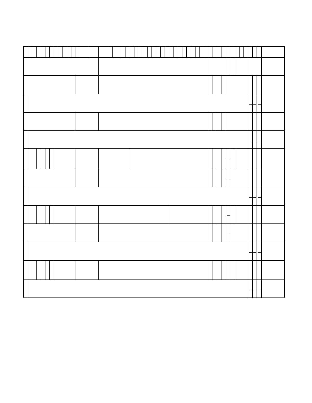
VMX SUPPORT FOR ADDRESS TRANSLATION
6
6
6
6
5
5
5
5
5
5
5
5
5
3
3
3
2
2
2
2
2
2
2
2
2
2
1
1
1
1
1
1
1
1
1
1
M1
M-1
3
2
1
0
9
8
7
6
5
4
3
2
1
2
1
0
9
8
7
6
5
4
3
2
1
0
9
8
7
6
5
4
3
2
1
0
9
8
7
6
5
4
3
2
1
0
S
A
EPT
EPT
S
Reserved
Address of EPT PML5 table or PML4 table
Rsvd.
/
PWL-
PS
EPTP3
S
2
D
1
MT
X
Ig
Ig
X
PML5E:
Ignored
Rsvd.
Address of EPT PML4 table
U
A
Reserved
5
W
R
n.
4
n.
present6
S
PML5E:
V
Ignored
0
0
0
not
E7
present
Ig
X
Ig
PML4E:
Ignored
Rsvd.
Address of EPT page-directory-pointer table
A
Reserved
X
W
R
n.
U
n.
present
S
PML4E:
V
Ignored
0
0
0
not
E
present
S
V
I
S
P
Physical
PDPTE:
G
Ig
X
P
EPT
V
Ign.SSIg
W
Ignored
Rsvd.
address of
Reserved
D
A
1
X
W
R
1GB
n.
9
P
n.
U
A
MT
E
8
1GB page
page
10
T
PDPTE:
Ig
X
Ig
Ignored
Rsvd.
Address of EPT page directory
A
0
Rsvd.
X
W
R
page
n.
U
n.
directory
S
PDPTE:
V
Ignored
0
0
0
not
E
present
I
S
S
V
PDE:
Ig
P
Physical address
Ig
X
P
EPT
V
Ign.
S
G
Ignored
Rsvd.
Reserved
D
A
1
X
W
R
2MB
n.
W
of 2MB page
n.
U
A
MT
E
S
P
page
T
PDE:
Ig
X
Ig
Ignored
Rsvd.
Address of EPT page table
A
0
Rsvd.
X
W
R
page
n.
U
n.
table
S
PDE:
V
Ignored
0
0
0
not
E
present
S
I
S
S
V
I
PTE:
Ig
P
Ig
P
Ig
X
P
EPT
V
S
G
Ignored
Rsvd.
Physical address of 4KB page
D
A
g
X
W
R
4KB
n.
P
n.
W
n.
U
A
MT
E
11
S
P
n
page
T
S
PTE:
V
Ignored
0
0
0
not
E
present
Figure 31-1. Formats of EPTP and EPT Paging-Structure Entries
NOTES:
1. M is an abbreviation for MAXPHYADDR. See Section 31.3.1.
2. Supervisor shadow-stack control.
3. See Section 27.6.11 for details of the EPTP.
4. Execute access for user-mode linear addresses. If the “mode-based execute control for EPT” VM-execution control is 0, this bit is
ignored.
5. Execute access. If the “mode-based execute control for EPT” VM-execution control is 1, this bit controls execute access for supervi-
sor-mode linear addresses.
Vol. 3C
31-13
VMX SUPPORT FOR ADDRESS TRANSLATION
6. If the “mode-based execute control for EPT” VM-execution control is 1, an EPT paging-structure entry is present if any of bits 2:0 or
bit 10 is 1. This table does not comprehend that fact.
7. Suppress #VE. If the “EPT-violation #VE” VM-execution control is 0, this bit is ignored.
8. Supervisor shadow-stack page. If bit 7 of the EPTP is 0, this bit is ignored.
9. Paging-write access. If the “EPT paging-write control” VM-execution control is 0, this bit is ignored.
10. Verify guest paging. If the “guest-paging verification” VM-execution control is 0, this bit is ignored.
11. Sub-page write permissions. If the “sub-page write permissions for EPT” VM-execution control is 0, this bit is ignored.
•
The access is a data write and, for any byte to be written, bit 1 (write access) was clear in any of the EPT
paging-structure entries used to translate the guest-physical address of the byte. Writes by the logical
processor to guest paging structures to update accessed and dirty flags are considered to be data writes.
If bit 6 of the EPT pointer (EPTP) is 1 (enabling accessed and dirty flags for EPT), processor accesses to guest
paging-structure entries are treated as writes with regard to EPT violations. Thus, if bit 1 is clear in any of the
EPT paging-structure entries used to translate the guest-physical address of a guest paging-structure entry, an
attempt to use that entry to translate a linear address causes an EPT violation.
(This does not apply to loads of the PDPTE registers by the MOV to CR instruction for PAE paging; see Section
5.4.1. Those loads of guest PDPTEs are treated as reads and do not cause EPT violations due to a guest-physical
address not being writable.)
Processor writes to guest paging structures to update accessed and dirty flags are called paging writes.
(When accessed and dirty flags for EPT are enabled all processor accesses to guest paging structures are
considered paging writes.) If the “EPT paging-write control” VM-execution control is 1, clearing the write-
access bit in the EPT paging-structure entry that maps a page does not prevent a paging write if bit 58 (paging-
write access) in that entry is 1. (EPT paging-structure entries that reference other EPT paging structures do not
use bit 58, and it remains the case that they must set the write-access bit for paging writes to be allowed.)
If the “sub-page write permissions for EPT” VM-execution control is 1, data writes to a guest-physical address
that would cause an EPT violation (as indicated above) do not do so in certain situations. If the guest-physical
address is mapped using a 4-KByte page and bit 61 (sub-page write permissions) of the EPT PTE used to map
the page is 1, writes to certain 128-byte sub-pages may be allowed. See Section 31.3.4 for details.
•
The access is an instruction fetch and the EPT paging structures prevent execute access to any of the bytes
being fetched. Whether this occurs depends upon the setting of the “mode-based execute control for EPT” VM-
execution control:
- If the control is 0, an instruction fetch from a byte is prevented if bit 2 (execute access) was clear in any of
the EPT paging-structure entries used to translate the guest-physical address of the byte.
- If the control is 1, an instruction fetch from a byte is prevented in either of the following cases:
• Paging maps the linear address of the byte as a supervisor-mode address and bit 2 (execute access for
supervisor-mode linear addresses) was clear in any of the EPT paging-structure entries used to
translate the guest-physical address of the byte.
Paging maps a linear address as a supervisor-mode address if the U/S flag (bit 2) is 0 in at least one of
the paging-structure entries controlling the translation of the linear address.
• Paging maps the linear address of the byte as a user-mode address and bit 10 (execute access for user-
mode linear addresses) was clear in any of the EPT paging-structure entries used to translate the guest-
physical address of the byte.
Paging maps a linear address as a user-mode address if the U/S flag is 1 in all of the paging-structure
entries controlling the translation of the linear address. If paging is disabled (CR0.PG = 0), every linear
address is a user-mode address.
•
If supervisor shadow-stack control is enabled (by setting bit 7 of EPTP), the access is a supervisor shadow-
stack access, and the EPT paging-structure entries used to translate the guest-physical address of the access
disallow supervisor shadow-stack accesses. Such an access is disallowed if any of the following hold:
- Bit 0 (read access) is clear in any EPT paging-structure entry used to translate the guest-physical address
of the access.
31-14
Vol. 3C
VMX SUPPORT FOR ADDRESS TRANSLATION
- Bit 1 (write access) is clear in any EPT paging-structure entry that references an EPT paging structure in the
translation of the guest-physical address. (Clearing bit 1 in the EPT paging-structure entry that maps the
page of the guest-physical address does not disallow shadow-stack reads and writes.)
- Bit 60 (supervisor-shadow stack access) is clear in the EPT paging-structure entry that maps the page of
the guest-physical address.
Supervisor shadow-stack control and the supervisor-shadow stack access bits in EPT paging-structure entries
do not affect other accesses (including user shadow-stack accesses).
• If the “guest-paging verification” and “EPT paging-write control” VM-execution controls are both 1, guest-
paging verification is performed for certain accesses related to translation of a linear address.
Specifically, guest-paging verification may apply to an access using a guest-physical address to the guest
paging-structure entry that maps a page for the linear address (see Chapter 5, “Paging”). It applies if bit 57
(verify guest paging) is set in the EPT paging-structure entry that maps a page for that guest-physical address.
When guest-paging verification occurs, there is an EPT violation if bit 58 (paging-write access) is clear in the
EPT paging-structure entry that was used to map a page for the guest-physical address of any guest paging-
structure entry that was used during translation of the original linear address.1
See Section 31.3.3.3 for details regarding the prioritization of such EPT violations relative to any page faults
that may occur due to the original reference to the linear address being translated.
31.3.3.3 Prioritization of EPT Misconfigurations and EPT Violations
The translation of a linear address to a physical address requires one or more translations of guest-physical
addresses using EPT (see Section 31.3.1). This section specifies the relative priority of EPT-induced VM exits with
respect to each other and to other events that may be encountered when accessing memory using a linear address.
For an access to a guest-physical address, determination of whether an EPT misconfiguration or an EPT violation
occurs is based on an iterative process:2
1. An EPT paging-structure entry is read (initially, this is an EPT PML5 entry or an EPT PML4 entry):
a. If the entry is not present (see Section 31.3.2), an EPT violation occurs.
b. If the entry is present but its contents are not configured properly (see Section 31.3.3.1), an EPT miscon-
figuration occurs.
c. If the entry is present and its contents are configured properly, operation depends on whether the entry
references another EPT paging structure (or if instead it is an EPT PDPTE or EPT PDE with bit 7 set to 1, or
an EPT PTE):
i) If the entry does reference another EPT paging structure, an entry from that structure is accessed;
step 1 is executed for that other entry.
ii) Otherwise, the entry is used to produce the ultimate physical address (the translation of the original
guest-physical address); step 2 is executed.
2. Once the ultimate physical address is determined, the privileges determined by the EPT paging-structure
entries are evaluated:
a. If the access to the guest-physical address is not allowed by these privileges (see Section 31.3.3.2), an EPT
violation occurs.
b. If the access to the guest-physical address is allowed by these privileges, memory is accessed using the
ultimate physical address.
If CR0.PG = 1, the translation of a linear address is also an iterative process, with the processor first accessing an
entry in the guest paging structure referenced by the guest-physical address in CR3,3 then accessing an entry in
1. When there is a restart of HLAT paging (see Section 5.5), the guest paging-structure entries used by HLAT paging (prior to the
restart) are not relevant to guest-paging verification.
2. This is a simplification of the more detailed description given in Section 31.3.2.
3. If PAE paging is in use, the processor instead uses the guest-physical address in the appropriate PDPTE register. If HLAT paging is
enabled, the processor instead uses the HLATP VMCS field. For simplicity, the remainder of this section refers only to CR3.
Vol. 3C
31-15
VMX SUPPORT FOR ADDRESS TRANSLATION
another guest paging structure referenced by the guest-physical address in the first guest paging-structure entry,
etc. Each guest-physical address is itself translated using EPT and may cause an EPT-induced VM exit. The
following items detail how page faults and EPT-induced VM exits are recognized during this iterative process:
1. An attempt is made to access a guest paging-structure entry with a guest-physical address (initially, the
address in CR3.
a. If the access fails because of an EPT misconfiguration or an EPT violation (see above), an EPT-induced
VM exit occurs.
b. If the access does not cause an EPT-induced VM exit, the translation continues. If guest-paging verification
is enabled (see Section 31.3.3.2), the processor notes whether the EPT paging-structure entry used to map
a page for the guest-physical address set bit 58 (paging write). Then, bit 0 (the present flag) of the guest
paging-structure entry is consulted:
i) If the present flag is 0 or any reserved bit is set, a page fault occurs.
ii) If the present flag is 1, no reserved bit is set, operation depends on whether the entry references
another guest paging structure (whether it is a guest PDE with PS = 1 or a guest PTE):
• If the entry does reference another guest paging structure, an entry from that structure is
accessed; step 1 is executed for that other entry.
• Otherwise, the entry is used to produce the ultimate guest-physical address (the translation of the
original linear address); step 2 is executed.
2. Once the ultimate guest-physical address is determined, the privileges determined by the guest paging-
structure entries are evaluated:
a. If the access to the linear address is not allowed by these privileges (e.g., it was a write to a read-only
page), a page fault occurs.
b. If the access to the linear address is allowed by these privileges, an attempt is made to access memory at
the ultimate guest-physical address:
i) If the access fails because of an EPT misconfiguration or an EPT violation (see above), an EPT-induced
VM exit occurs. It is at this point that guest-paging verification occurs (if enabled), using the paging-
write bits that were noted at occurrences of step 1b above (see Section 31.3.3.2 for details of guest-
paging verification).
ii) If the access does not cause an EPT-induced VM exit, memory is accessed using the ultimate physical
address (the translation, using EPT, of the ultimate guest-physical address).
If CR0.PG = 0, a linear address is treated as a guest-physical address and is translated using EPT (see above). This
process, if it completes without an EPT violation or EPT misconfiguration, produces a physical address and deter-
mines the privileges allowed by the EPT paging-structure entries. If these privileges do not allow the access to the
physical address (see Section 31.3.3.2), an EPT violation occurs. Otherwise, memory is accessed using the physical
address.
31.3.4 Sub-Page Write Permissions
Section 31.3.3.2 explained how EPT enforces the access rights for guest-physical addresses using EPT violations.
Since these access rights are determined using the EPT paging-structure entries that are used to translate a guest-
physical address, their granularity is limited to that which is used to map pages (1-GByte, 2-MByte, or 4-KByte).
The sub-page write-permission feature allows the control of write accesses to guest-physical addresses to be
controlled at finer granularity. Sub-page write permissions allow write accesses to be controlled at the granularity
of naturally aligned 128-byte sub-pages. Specifically, the feature allows writes to selected sub-pages of 4-KByte
page that would otherwise not be writable.
Sub-page write permissions are enabled setting the “sub-page write permissions for EPT” VM-execution control to
1. The remainder of this section describes changes to processor operation with this control setting.
Section 31.3.4.1 identifies the data accesses that are eligible for sub-page write permissions. Section 31.3.4.2
explains how the processor determines whether to allow such an access.
31-16
Vol. 3C
VMX SUPPORT FOR ADDRESS TRANSLATION
31.3.4.1 Write Accesses That Are Eligible for Sub-Page Write Permissions
A guest-physical address is eligible for sub-page write permissions if writes to it would be disallowed following
Section 31.3.3.2: bit 1 (write access) is clear in any of the EPT paging-structure entries used to translate the guest-
physical address. Guest-physical addresses to which writes would be disallowed for other reasons (e.g., the trans-
lation encounters an EPT paging-structure entry that is not present) are not eligible for sub-page write permis-
sions.
In addition, a guest-physical address is eligible for sub-page write permissions only if it is mapped using a 4-KByte
page and bit 61 (sub-page write permissions) of the EPT PTE used to map the page is 1. (Guest-physical addresses
mapped with larger pages are not eligible for sub-page write permissions.)
For some memory accesses, the processor ignores bit 61 in an EPT PTE used to map a 4-KByte page and does not
apply sub-page write permissions to the access. (In such a case, the access causes an EPT violation when indicated
by the conditions given in Section 31.3.3.2.) Sub-page write permissions never apply to the following accesses:
• A write access performed within a transactional region.
• A write access by an enclave to an address within the enclave's ELRANGE. (Sub-page write permissions may
apply to write accesses by an enclaves to addresses outside its ELRANGE.)
• A write access to the enclave page cache (EPC) by an Intel SGX instruction.
• A write access performed for architectural PEBS.
• A write access to a guest paging structure to update an accessed or dirty flag.
• Processor accesses to guest paging-structure entries when accessed and dirty flags for EPT are enabled (such
accesses are treated as writes with regard to EPT violations).
There are additional accesses to which sub-page write permissions might not be applied (behavior is model-
specific). The following items enumerate examples:
• A write access that crosses two 4-KByte pages. In this case, sub-page permissions may be applied to neither
or to only one of the pages. (There is no write to either page unless the write is allowed to both pages.)
• A write access by an instruction that performs multiple write accesses (sub-page write permissions are
intended principally for basic instructions such as AND, MOV, OR, TEST, XCHG, and XOR).
If a guest-physical address is eligible for sub-page write permissions, the processor determines whether to allow
write to the address using the process described in Section 31.3.4.2.
If a guest-physical address is eligible for sub-page write permissions and that address translates to an address on
the APIC-access page (see Section 32.4), the processor may treat a write access to the address as if the “virtualize
APIC accesses” VM-execution control were 0. For that reason, it is recommended that software not configure any
guest-physical address that translates to an address on the APIC-access page to be eligible for sub-page write
permissions.
31.3.4.2 Determining an Access’s Sub-Page Write Permission
Sub-page write permissions control write accesses individually to each of the 32 128-byte sub-pages of a 4-KByte
page. Bits 11:7 of guest-physical address identify the sub-page.
For each guest-physical address eligible for sub-page write permissions, there is a 64-bit sub-page permission
vector (SPP vector). All addresses on a 4-KByte page use the same SPP vector. If an address’s sub-page number
(bits 11:7 of the address) is S, writes to address are allowed if and only if bit 2S of the sub-page permission is set
to 1. (The bits at odd positions in a SPP vector are not used and must be zero.)
Each page’s SPP vector is located in memory. For a write to a guest-physical address eligible for sub-page write
permissions, the processor uses the following process to locate the address’s SPP vector:
1. The SPPTP (sub-page-permission-table pointer) VM-execution control field contains the physical address of the
4-KByte root SPP table (SSPL4 table). Bits 47:39 of the guest-physical address identify a 64-bit entry in that
table, called an SPPL4E.
2. A 4-KByte SPPL3 table is located at the physical address in the selected SPPL4E. Bits 38:30 of the guest-
physical address identify a 64-bit entry in that table, called an SPPL3E.
Vol. 3C
31-17
VMX SUPPORT FOR ADDRESS TRANSLATION
3. A 4-KByte SPPL2 table is located at the physical address in the selected SPPL3E. Bits 29:21 of the guest-
physical address identify a 64-bit entry in that table, called an SPPL2E.
4. A 4-KByte SPP-vector table (SSPL1 table) is located at the physical address in the selected SPPL2E. Bits 20:12
of the guest-physical address identify the 64-bit SPP vector for the address. As noted earlier, bit 2S of the sub-
page permission vector determines whether the address may be written, where S is the value of address
bits 11:7.
(The memory type used to access these tables is reported in bits 53:50 of the IA32_VMX_BASIC MSR. See
Appendix A.1.)
A write access to multiple 128-byte sub-pages on a single 4-KByte page is allowed only if the indicated bit in the
page’s SPP vector for each of those sub-pages is set to 1. The following items apply to cases in which an access
writes to two 4-KByte pages:
• If a write to either page would be disallowed according to Section 31.3.3.2, the access might be disallowed
even if the guest-physical address of that page is eligible for sub-page write permissions. (This behavior is
model-specific.)
• The access is allowed only if, for each page, either (1) a write to the page would be allowed following Section
31.3.3.2; or (2) both (a) the guest-physical address of that page is eligible for sub-page write permissions; and
(b) the page’s sub-page vector allows the write (as described above).
Bit 0 of each entry (SPPL4E, SPPL3E, or SPPL2E) is the entry’s valid bit. If the process above accesses an entry in
which this bit is 0, the process stops and the logical processor incurs an SPP miss.
In each entry (SPPL4E, SPPL3E, or SPPL2E), bits 11:1 are reserved, as are bits 63:MAXPHYADDR (see Section
31.3.1). If the process above accesses an entry in which the valid bit is 1 and in which some reserved bit is set, the
process stops and the logical processor incurs an SPP misconfiguration. Bits in an SPP vector in odd positions are
also reserved; an SPP misconfiguration occurs also any of those bits are set in the final SPP vector.
SPP misses and SPP misconfigurations are called SPP-related events and cause VM exits.
31.3.5 Accessed and Dirty Flags for EPT
The Intel 64 architecture supports accessed and dirty flags in ordinary paging-structure entries (see Section
5.8). Some processors also support corresponding flags in EPT paging-structure entries. Software should read the
VMX capability MSR IA32_VMX_EPT_VPID_CAP (see Appendix A.10) to determine whether the processor supports
this feature.
Software can enable accessed and dirty flags for EPT using bit 6 of the extended-page-table pointer (EPTP), a VM-
execution control field (see Table 27-9 in Section 27.6.11). If this bit is 1, the processor will set the accessed and
dirty flags for EPT as described below. In addition, setting this flag causes processor accesses to guest paging-
structure entries to be treated as writes (see below and Section 31.3.3.2).
For any EPT paging-structure entry that is used during guest-physical-address translation, bit 8 is the accessed
flag. For a EPT paging-structure entry that maps a page (as opposed to referencing another EPT paging structure),
bit 9 is the dirty flag.
Whenever the processor uses an EPT paging-structure entry as part of guest-physical-address translation, it sets
the accessed flag in that entry (if it is not already set).
Whenever there is a write to a guest-physical address, the processor sets the dirty flag (if it is not already set) in
the EPT paging-structure entry that identifies the final physical address for the guest-physical address (either an
EPT PTE or an EPT paging-structure entry in which bit 7 is 1).
When accessed and dirty flags for EPT are enabled, processor accesses to guest paging-structure entries are
treated as writes (see Section 31.3.3.2). Thus, such an access will cause the processor to set the dirty flag in the
EPT paging-structure entry that identifies the final physical address of the guest paging-structure entry.
(This does not apply to loads of the PDPTE registers for PAE paging by the MOV to CR instruction; see Section 5.4.1.
Those loads of guest PDPTEs are treated as reads and do not cause the processor to set the dirty flag in any EPT
paging-structure entry.)
These flags are “sticky,” meaning that, once set, the processor does not clear them; only software can clear them.
31-18
Vol. 3C
VMX SUPPORT FOR ADDRESS TRANSLATION
A processor may cache information from the EPT paging-structure entries in TLBs and paging-structure caches
(see Section 31.4). This fact implies that, if software changes an accessed flag or a dirty flag from 1 to 0, the
processor might not set the corresponding bit in memory on a subsequent access using an affected guest-physical
address.
31.3.6 Page-Modification Logging
When accessed and dirty flags for EPT are enabled, software can track writes to guest-physical addresses using a
feature called page-modification logging.
Software can enable page-modification logging by setting the “enable PML” VM-execution control (see Table 27-7
in Section 27.6.2). When this control is 1, the processor adds entries to the page-modification log as described
below. The page-modification log is a 4-KByte region of memory located at the physical address in the PML address
VM-execution control field. The page-modification log consists of 512 64-bit entries; the PML index VM-execution
control field indicates the next entry to use.
Before allowing a guest-physical access, the processor may determine that it first needs to set an accessed or dirty
flag for EPT (see Section 31.3.5). When this happens, the processor examines the PML index. If the PML index is
not in the range 0-511, there is a page-modification log-full event and a VM exit occurs. In this case, the
accessed or dirty flag is not set, and the guest-physical access that triggered the event does not occur.
If instead the PML index is in the range 0-511, the processor proceeds to update accessed or dirty flags for EPT as
described in Section 31.3.5. If the processor updated a dirty flag for EPT (changing it from 0 to 1), it then operates
as follows:
1. The guest-physical address of the access is written to the page-modification log. Specifically, the guest-
physical address is written to physical address determined by adding 8 times the PML index to the PML address.
Bits 11:0 of the value written are always 0 (the guest-physical address written is thus 4-KByte aligned).
2. The PML index is decremented by 1 (this may cause the value to transition from 0 to FFFFH).
Because the processor decrements the PML index with each log entry, the value may transition from 0 to FFFFH. At
that point, no further logging will occur, as the processor will determine that the PML index is not in the range 0-
511 and will generate a page-modification log-full event (see above).
31.3.7 EPT and Memory Typing
This section specifies how a logical processor determines the memory type use for a memory access while EPT is in
use. (See Chapter 14, “Memory Cache Control‚” of the Intel® 64 and IA-32 Architectures Software Developer’s
Manual, Volume 3A, for details of memory typing in the Intel 64 architecture.) Section 31.3.7.1 explains how the
memory type is determined for accesses to the EPT paging structures. Section 31.3.7.2 explains how the memory
type is determined for an access using a guest-physical address that is translated using EPT.
31.3.7.1 Memory Type Used for Accessing EPT Paging Structures
This section explains how the memory type is determined for accesses to the EPT paging structures. The determi-
nation is based first on the value of bit 30 (cache disable-CD) in control register CR0:
• If CR0.CD = 0, the memory type used for any such reference is the EPT paging-structure memory type, which
is specified in bits 2:0 of the extended-page-table pointer (EPTP), a VM-execution control field (see Section
27.6.11). A value of 0 indicates the uncacheable type (UC), while a value of 6 indicates the write-back type
(WB). Other values are reserved.
• If CR0.CD = 1, the memory type used for any such reference is uncacheable (UC).
The MTRRs have no effect on the memory type used for an access to an EPT paging structure.
31.3.7.2 Memory Type Used for Translated Guest-Physical Addresses
The effective memory type of a memory access using a guest-physical address (an access that is translated
using EPT) is the memory type that is used to access memory. The effective memory type is based on the value of
Vol. 3C
31-19
VMX SUPPORT FOR ADDRESS TRANSLATION
bit 30 (cache disable-CD) in control register CR0; the last EPT paging-structure entry used to translate the guest-
physical address (either an EPT PDE with bit 7 set to 1 or an EPT PTE); and the PAT memory type (see below):
• The PAT memory type depends on the value of CR0.PG:
- If CR0.PG = 0, the PAT memory type is WB (writeback).1
- If CR0.PG = 1, the PAT memory type is the memory type selected from the IA32_PAT MSR as specified in
Section 14.12.3, “Selecting a Memory Type from the PAT.”2
• The EPT memory type is specified in bits 5:3 of the last EPT paging-structure entry: 0 = UC; 1 = WC; 4 = WT;
5 = WP; and 6 = WB. Other values are reserved and cause EPT misconfigurations (see Section 31.3.3).
• If CR0.CD = 0, the effective memory type depends upon the value of bit 6 of the last EPT paging-structure
entry:
- If the value is 0, the effective memory type is the combination of the EPT memory type and the PAT memory
type specified in Table 14-7 in Section 14.5.2.2, using the EPT memory type in place of the MTRR memory
type.
- If the value is 1, the memory type used for the access is the EPT memory type. The PAT memory type is
ignored.
• If CR0.CD = 1, the effective memory type is UC.
The MTRRs have no effect on the memory type used for an access to a guest-physical address.
31.4
CACHING TRANSLATION INFORMATION
Processors supporting Intel® 64 and IA-32 architectures may accelerate the address-translation process by
caching on the processor data from the structures in memory that control that process. Such caching is discussed
in Section 5.10, “Caching Translation Information,” in the Intel® 64 and IA-32 Architectures Software Developer’s
Manual, Volume 3A. The current section describes how this caching interacts with the VMX architecture.
The VPID and EPT features of the architecture for VMX operation augment this caching architecture. EPT defines
the guest-physical address space and defines translations to that address space (from the linear-address space)
and from that address space (to the physical-address space). Both features control the ways in which a logical
processor may create and use information cached from the paging structures.
Section 31.4.1 describes the different kinds of information that may be cached. Section 31.4.2 specifies when such
information may be cached and how it may be used. Section 31.4.3 details how software can invalidate cached
information.
31.4.1 Information That May Be Cached
Section 5.10, “Caching Translation Information,” in the Intel® 64 and IA-32 Architectures Software Developer’s
Manual, Volume 3A, identifies two kinds of translation-related information that may be cached by a logical
processor: translations, which are mappings from linear page numbers to physical page frames, and paging-
structure caches, which map the upper bits of a linear page number to information from the paging-structure
entries used to translate linear addresses matching those upper bits.
The same kinds of information may be cached when VPIDs and EPT are in use. A logical processor may cache and
use such information based on its function. Information with different functionality is identified as follows:
1. If the capability MSR IA32_VMX_CR0_FIXED0 reports that CR0.PG must be 1 in VMX operation, CR0.PG can be 0 in VMX non-root
operation only if the “unrestricted guest” VM-execution control and bit 31 of the primary processor-based VM-execution controls are
both 1.
2. Table 14-11 in Section 14.12.3, “Selecting a Memory Type from the PAT,” illustrates how the PAT memory type is selected based on
the values of the PAT, PCD, and PWT bits in a page-table entry (or page-directory entry with PS = 1). For accesses to a guest paging-
structure entry X, the PAT memory type is selected from the table by using a value of 0 for the PAT bit with the values of PCD and
PWT from the paging-structure entry Y that references X (or from CR3 if X is in the root paging structure). With PAE paging, the PAT
memory type for accesses to the PDPTEs is WB.
31-20
Vol. 3C
VMX SUPPORT FOR ADDRESS TRANSLATION
• Linear mappings.1 There are two kinds:
- Linear translations. Each of these is a mapping from a linear page number to the physical page frame to
which it translates, along with information about access privileges and memory typing.
- Linear paging-structure-cache entries. Each of these is a mapping from the upper portion of a linear
address to the physical address of the paging structure used to translate the corresponding region of the
linear-address space, along with information about access privileges. For example, bits 47:39 of a linear
address would map to the address of the relevant page-directory-pointer table.
Linear mappings do not contain information from any EPT paging structure.
• Guest-physical mappings.2 There are two kinds:
- Guest-physical translations. Each of these is a mapping from a guest-physical page number to the physical
page frame to which it translates, along with information about access privileges and memory typing.
- Guest-physical paging-structure-cache entries. Each of these is a mapping from the upper portion of a
guest-physical address to the physical address of the EPT paging structure used to translate the corre-
sponding region of the guest-physical address space, along with information about access privileges.
The information in guest-physical mappings about access privileges and memory typing is derived from EPT
paging structures.
• Combined mappings.3 There are two kinds:
- Combined translations. Each of these is a mapping from a linear page number to the physical page frame
to which it translates, along with information about access privileges and memory typing.
- Combined paging-structure-cache entries. Each of these is a mapping from the upper portion of a linear
address to the physical address of the paging structure used to translate the corresponding region of the
linear-address space, along with information about access privileges.
The information in combined mappings about access privileges and memory typing is derived from both guest
paging structures and EPT paging structures.
Guest-physical mappings and combined mappings may also include SPP vectors and information about the data
structures used to locate SPP vectors (see Section 31.3.4.2).
31.4.2 Creating and Using Cached Translation Information
The following items detail the creation of the mappings described in the previous section:4
• The following items describe the creation of mappings while EPT is not in use (including execution outside VMX
non-root operation):
- Linear mappings may be created. They are derived from the paging structures referenced (directly or
indirectly) by the current value of CR3 and are associated with the current VPID and the current PCID.
- No linear mappings are created with information derived from paging-structure entries that are not present
(bit 0 is 0) or that set reserved bits. For example, if a PTE is not present, no linear mapping are created for
any linear page number whose translation would use that PTE.
- No guest-physical or combined mappings are created while EPT is not in use.
• The following items describe the creation of mappings while EPT is in use:
- Guest-physical mappings may be created. They are derived from the EPT paging structures referenced
(directly or indirectly) by bits 51:12 of the current EPTP. These 40 bits contain the address of the EPT root
1. Earlier versions of this manual used the term “VPID-tagged” to identify linear mappings.
2. Earlier versions of this manual used the term “EPTP-tagged” to identify guest-physical mappings.
3. Earlier versions of this manual used the term “dual-tagged” to identify combined mappings.
4. This section associated cached information with the current VPID and PCID. If PCIDs are not supported or are not being used (e.g.,
because CR4.PCIDE = 0), all the information is implicitly associated with PCID 000H; see Section 5.10.1, “Process-Context Identifiers
(PCIDs),” in the Intel® 64 and IA-32 Architectures Software Developer’s Manual, Volume 3A.
Vol. 3C
31-21
VMX SUPPORT FOR ADDRESS TRANSLATION
table (a EPT PML4 table with 4-level EPT or a EPT PML5 table with 5-level EPT); the notation EPTRTA refers
to those 40 bits. Newly created guest-physical mappings are associated with the current EPTRTA.
- Combined mappings may be created. They are derived from the EPT paging structures referenced (directly
or indirectly) by the current EPTRTA. If CR0.PG = 1, they are also derived from the paging structures
referenced (directly or indirectly) by the current value of CR3. They are associated with the current VPID,
the current PCID, and the current EPTRTA.1 No combined paging-structure-cache entries are created if
CR0.PG = 0.2
- No guest-physical mappings or combined mappings are created with information derived from EPT paging-
structure entries that are not present (see Section 31.3.2) or that are misconfigured (see Section
31.3.3.1).
- No combined mappings are created with information derived from guest paging-structure entries that are
not present or that set reserved bits.
- No linear mappings are created while EPT is in use.
As explained in Section 35.3.2, address translation is different in SEAM non-root operation: translation of SEAM-
guest private addresses use EPTP (as is done in VMX non-root operation); translation of SEAM-guest shared
addresses use the SEAM shared EPT pointer (a different VMCS field). Nevertheless, all guest-physical mappings
and combined mappings created and used in SEAM non-root operation (including those for SEAM-guest shared
addresses) are associated with the current EPTRTA (derived from EPTP).
The following items detail the use of the various mappings:
• If EPT is not in use (e.g., when outside VMX non-root operation), a logical processor may use cached mappings
as follows:
- For accesses using linear addresses, it may use linear mappings associated with the current VPID and the
current PCID. It may also use global TLB entries (linear mappings) associated with the current VPID and
any PCID.
- No guest-physical or combined mappings are used while EPT is not in use.
• If EPT is in use, a logical processor may use cached mappings as follows:
- For accesses using linear addresses, it may use combined mappings associated with the current VPID, the
current PCID, and the current EPTRTA. It may also use global TLB entries (combined mappings) associated
with the current VPID, the current EPTRTA, and any PCID.
- For accesses using guest-physical addresses, it may use guest-physical mappings associated with the
current EPTRTA.
- No linear mappings are used while EPT is in use.
31.4.3 Invalidating Cached Translation Information
Software modifications of paging structures (including EPT paging structures and the data structures used to locate
SPP vectors) may result in inconsistencies between those structures and the mappings cached by a logical
processor. Certain operations invalidate information cached by a logical processor and can be used to eliminate
such inconsistencies.
31.4.3.1 Operations that Invalidate Cached Mappings
The following operations invalidate cached mappings as indicated:
• Operations that architecturally invalidate entries in the TLBs or paging-structure caches independent of VMX
operation (e.g., the INVLPG and INVPCID instructions) invalidate linear mappings and combined mappings.3
1. At any given time, a logical processor may be caching combined mappings for a VPID and a PCID that are associated with different
EPTRTAs. Similarly, it may be caching combined mappings for an EPTRTA that are associated with different VPIDs and PCIDs.
2. If the capability MSR IA32_VMX_CR0_FIXED0 reports that CR0.PG must be 1 in VMX operation, CR0.PG can be 0 in VMX non-root
operation only if the “unrestricted guest” VM-execution control and bit 31 of the primary processor-based VM-execution controls are
both 1.
31-22
Vol. 3C
VMX SUPPORT FOR ADDRESS TRANSLATION
They are required to do so only for the current VPID (but, for combined mappings, all EPTRTAs). Linear
mappings for the current VPID are invalidated even if EPT is in use.1 Combined mappings for the current
VPID are invalidated even if EPT is not in use.2
•
An EPT violation invalidates any guest-physical mappings (associated with the current EPTRTA) that would be
used to translate the guest-physical address that caused the EPT violation. If that guest-physical address was
the translation of a linear address, the EPT violation also invalidates any combined mappings for that linear
address associated with the current PCID, the current VPID and the current EPTRTA.
•
If the “enable VPID” VM-execution control is 0, VM entries and VM exits invalidate linear mappings and
combined mappings associated with VPID 0000H (for all PCIDs). Combined mappings for VPID 0000H are
invalidated for all EPTRTAs.3
•
Execution of the INVVPID instruction invalidates linear mappings and combined mappings. Invalidation is
based on instruction operands, called the INVVPID type and the INVVPID descriptor. Four INVVPID types are
currently defined:
- Individual-address. If the INVVPID type is 0, the logical processor invalidates linear mappings and
combined mappings associated with the VPID specified in the INVVPID descriptor and that would be used
to translate the linear address specified in of the INVVPID descriptor. Linear mappings and combined
mappings for that VPID and linear address are invalidated for all PCIDs and, for combined mappings, all
EPTRTAs. (The instruction may also invalidate mappings associated with other VPIDs and for other linear
addresses.)
- Single-context. If the INVVPID type is 1, the logical processor invalidates all linear mappings and
combined mappings associated with the VPID specified in the INVVPID descriptor. Linear mappings and
combined mappings for that VPID are invalidated for all PCIDs and, for combined mappings, all EPTRTAs.
(The instruction may also invalidate mappings associated with other VPIDs.)
- All-context. If the INVVPID type is 2, the logical processor invalidates linear mappings and combined
mappings associated with all VPIDs except VPID 0000H and with all PCIDs. (The instruction may also
invalidate linear mappings with VPID 0000H.) Combined mappings are invalidated for all EPTRTAs.
- Single-context-retaining-globals. If the INVVPID type is 3, the logical processor invalidates linear
mappings and combined mappings associated with the VPID specified in the INVVPID descriptor. Linear
mappings and combined mappings for that VPID are invalidated for all PCIDs and, for combined mappings,
all EPTRTAs. The logical processor is not required to invalidate information that was used for global trans-
lations (although it may do so). See Section 5.10, “Caching Translation Information,” for details regarding
global translations. (The instruction may also invalidate mappings associated with other VPIDs.)
See Chapter 33 for details of the INVVPID instruction. See Section 31.4.3.3 for guidelines regarding use of this
instruction.4
•
Execution of the INVEPT instruction invalidates guest-physical mappings and combined mappings. Invalidation
is based on instruction operands, called the INVEPT type and the INVEPT descriptor. Two INVEPT types are
currently defined:
- Single-context. If the INVEPT type is 1, the logical processor invalidates all guest-physical mappings and
combined mappings associated with the EPTRTA specified in the INVEPT descriptor. Combined mappings for
that EPTRTA are invalidated for all VPIDs and all PCIDs. (The instruction may invalidate mappings
associated with other EPTRTAs.)
3.
See Section 5.10.4, “Invalidation of TLBs and Paging-Structure Caches,” in the Intel® 64 and IA-32 Architectures Software Devel-
oper’s Manual, Volume 3A, for an enumeration of operations that architecturally invalidate entries in the TLBs and paging-structure
caches independent of VMX operation.
1.
While no linear mappings are created while EPT is in use, a logical processor may retain, while EPT is in use, linear mappings (for the
same VPID as the current one) there were created earlier, when EPT was not in use.
2.
While no combined mappings are created while EPT is not in use, a logical processor may retain, while EPT is in not use, combined
mappings (for the same VPID as the current one) there were created earlier, when EPT was in use.
3.
VM entries and VM exits in SEAM invalidate mappings for VPID 10000H instead of 0000H.
4.
Executions of INVVPID outside of SEAM (even those of the all-context type) are defined to invalidate only mappings associated for
VPIDs 0000H-FFFFH. Similarly, executions in SEAM apply only to mappings associated with VPIDS 10000H-1FFFFH (the all-context
type need not invalidate mappings for VPID 10000H).
Vol. 3C
31-23
VMX SUPPORT FOR ADDRESS TRANSLATION
- All-context. If the INVEPT type is 2, the logical processor invalidates guest-physical mappings and
combined mappings associated with all EPTRTAs (and, for combined mappings, for all VPIDs and PCIDs).
See Chapter 33 for details of the INVEPT instruction. See Section 31.4.3.4 for guidelines regarding use of this
instruction.1
• A power-up or a reset invalidates all linear mappings, guest-physical mappings, and combined mappings.
31.4.3.2 Operations that Need Not Invalidate Cached Mappings
The following items detail cases of operations that are not required to invalidate certain cached mappings:
• Operations that architecturally invalidate entries in the TLBs or paging-structure caches independent of VMX
operation are not required to invalidate any guest-physical mappings.
• The INVVPID instruction is not required to invalidate any guest-physical mappings.
• The INVEPT instruction is not required to invalidate any linear mappings.
• VMX transitions are not required to invalidate any guest-physical mappings. If the “enable VPID” VM-execution
control is 1, VMX transitions are not required to invalidate any linear mappings or combined mappings.
• The VMXOFF and VMXON instructions are not required to invalidate any linear mappings, guest-physical
mappings, or combined mappings.
A logical processor may invalidate any cached mappings at any time. For this reason, the operations identified
above may invalidate the indicated mappings despite the fact that doing so is not required.
31.4.3.3 Guidelines for Use of the INVVPID Instruction
The need for VMM software to use the INVVPID instruction depends on how that software is virtualizing memory.
If EPT is not in use, it is likely that the VMM is virtualizing the guest paging structures. Such a VMM may configure
the VMCS so that all or some of the operations that invalidate entries the TLBs and the paging-structure caches
(e.g., the INVLPG instruction) cause VM exits. If VMM software is emulating these operations, it may be necessary
to use the INVVPID instruction to ensure that the logical processor’s TLBs and the paging-structure caches are
appropriately invalidated.
Requirements of when software should use the INVVPID instruction depend on the specific algorithm being used for
page-table virtualization. The following items provide guidelines for software developers:
• Emulation of the INVLPG instruction may require execution of the INVVPID instruction as follows:
- The INVVPID type is individual-address (0).
- The VPID in the INVVPID descriptor is the one assigned to the virtual processor whose execution is being
emulated.
- The linear address in the INVVPID descriptor is that of the operand of the INVLPG instruction being
emulated.
• Some instructions invalidate all entries in the TLBs and paging-structure caches-except for global translations.
An example is the MOV to CR3 instruction. (See Section 5.10, “Caching Translation Information,” in the Intel®
64 and IA-32 Architectures Software Developer’s Manual, Volume 3A, for details regarding global translations.)
Emulation of such an instruction may require execution of the INVVPID instruction as follows:
- The INVVPID type is single-context-retaining-globals (3).
- The VPID in the INVVPID descriptor is the one assigned to the virtual processor whose execution is being
emulated.
• Some instructions invalidate all entries in the TLBs and paging-structure caches-including for global transla-
tions. An example is the MOV to CR4 instruction if the value of value of bit 4 (page global enable-PGE) is
changing. Emulation of such an instruction may require execution of the INVVPID instruction as follows:
- The INVVPID type is single-context (1).
1. All executions of INVEPT invalidate mappings associated with all VPID: those that are used outside of SEAM, 0000H-FFFFH, and
those that are used in SEAM, 10000H-1FFFFH.
31-24
Vol. 3C
VMX SUPPORT FOR ADDRESS TRANSLATION
- The VPID in the INVVPID descriptor is the one assigned to the virtual processor whose execution is being
emulated.
If EPT is not in use, the logical processor associates all mappings it creates with the current VPID, and it will use
such mappings to translate linear addresses. For that reason, a VMM should not use the same VPID for different
non-EPT guests that use different page tables. Doing so may result in one guest using translations that pertain to
the other.
If EPT is in use, the instructions enumerated above might not be configured to cause VM exits and the VMM might
not be emulating them. In that case, executions of the instructions by guest software properly invalidate the
required entries in the TLBs and paging-structure caches (see Section 31.4.3.1); execution of the INVVPID instruc-
tion is not required.
If EPT is in use, the logical processor associates all mappings it creates with the value of bits 51:12 of current EPTP.
If a VMM uses different EPTP values for different guests, it may use the same VPID for those guests. Doing so
cannot result in one guest using translations that pertain to the other.
The following guidelines apply more generally and are appropriate even if EPT is in use:
• As detailed in Section 32.4.5, an access to the APIC-access page might not cause an APIC-access VM exit if
software does not properly invalidate information that may be cached from the paging structures. If, at one
time, the current VPID on a logical processor was a non-zero value X, it is recommended that software use the
INVVPID instruction with the “single-context” INVVPID type and with VPID X in the INVVPID descriptor before
a VM entry on the same logical processor that establishes VPID X and either (a) the “virtualize APIC accesses”
VM-execution control was changed from 0 to 1; or (b) the value of the APIC-access address was changed.
• Software can use the INVVPID instruction with the “all-context” INVVPID type immediately after execution of
the VMXON instruction or immediately prior to execution of the VMXOFF instruction. Either prevents potentially
undesired retention of information cached from paging structures between separate uses of VMX operation.
31.4.3.4 Guidelines for Use of the INVEPT Instruction
The following items provide guidelines for use of the INVEPT instruction to invalidate information cached from the
EPT paging structures.
• Software should use the INVEPT instruction with the “single-context” INVEPT type after making any of the
following changes to an EPT paging-structure entry (the INVEPT descriptor should contain an EPTP value that
references - directly or indirectly - the modified EPT paging structure):
- Changing any of the privilege bits 2:0 from 1 to 0.1
- Changing the physical address in bits 51:12.
- Clearing bit 8 (the accessed flag) if accessed and dirty flags for EPT will be enabled.
- For an EPT PDPTE or an EPT PDE, changing bit 7 (which determines whether the entry maps a page).
- For the last EPT paging-structure entry used to translate a guest-physical address (an EPT PDPTE with bit 7
set to 1, an EPT PDE with bit 7 set to 1, or an EPT PTE), changing either bits 5:3 or bit 6. (These bits
determine the effective memory type of accesses using that EPT paging-structure entry; see Section
31.3.7.)
- For the last EPT paging-structure entry used to translate a guest-physical address (an EPT PDPTE with bit 7
set to 1, an EPT PDE with bit 7 set to 1, or an EPT PTE), clearing bit 9 (the dirty flag) if accessed and dirty
flags for EPT will be enabled.
• Software should use the INVEPT instruction with the “single-context” INVEPT type before a VM entry with an
EPTP value X such that X[6] = 1 (accessed and dirty flags for EPT are enabled) if the logical processor had
earlier been in VMX non-root operation with an EPTP value Y such that Y[6] = 0 (accessed and dirty flags for
EPT are not enabled) and Y[51:12] = X[51:12].
• Software should use the INVEPT instruction with the “single-context” INVEPT type before a VM entry with an
EPTP value X if the logical processor had earlier been in VMX non-root operation with an EPTP value Y such that
Y[5:3] ≠ X[5:3] (different EPT page-walk length) and Y[51:12] = X[51:12].
1. If the “mode-based execute control for EPT” VM-execution control is 1, software should use the INVEPT instruction after changing
privilege bit 10 from 1 to 0.
Vol. 3C
31-25
VMX SUPPORT FOR ADDRESS TRANSLATION
• Software may use the INVEPT instruction after modifying a present EPT paging-structure entry (see Section
31.3.2) to change any of the privilege bits 2:0 from 0 to 1.1 Failure to do so may cause an EPT violation that
would not otherwise occur. Because an EPT violation invalidates any mappings that would be used by the access
that caused the EPT violation (see Section 31.4.3.1), an EPT violation will not recur if the original access is
performed again, even if the INVEPT instruction is not executed.
• Because a logical processor does not cache any information derived from EPT paging-structure entries that are
not present (see Section 31.3.2) or misconfigured (see Section 31.3.3.1), it is not necessary to execute INVEPT
following modification of an EPT paging-structure entry that had been not present or misconfigured.
• As detailed in Section 32.4.5, an access to the APIC-access page might not cause an APIC-access VM exit if
software does not properly invalidate information that may be cached from the EPT paging structures. If EPT
was in use on a logical processor at one time with EPTP X, it is recommended that software use the INVEPT
instruction with the “single-context” INVEPT type and with EPTP X in the INVEPT descriptor before a VM entry
on the same logical processor that enables EPT with EPTP X and either (a) the “virtualize APIC accesses” VM-
execution control was changed from 0 to 1; or (b) the value of the APIC-access address was changed.
• Software can use the INVEPT instruction with the “all-context” INVEPT type immediately after execution of the
VMXON instruction or immediately prior to execution of the VMXOFF instruction. Either prevents potentially
undesired retention of information cached from EPT paging structures between separate uses of VMX
operation.
In a system containing more than one logical processor, software must account for the fact that information from
an EPT paging-structure entry may be cached on logical processors other than the one that modifies that entry. The
process of propagating the changes to a paging-structure entry is commonly referred to as “TLB shootdown.” A
discussion of TLB shootdown appears in Section 5.10.5, “Propagation of Paging-Structure Changes to Multiple
Processors,” in the Intel® 64 and IA-32 Architectures Software Developer’s Manual, Volume 3A.
1. If the “mode-based execute control for EPT” VM-execution control is 1, software may use the INVEPT instruction after modifying a
present EPT paging-structure entry to change privilege bit 10 from 0 to 1.
31-26
Vol. 3C
CHAPTER 32
APIC VIRTUALIZATION AND VIRTUAL INTERRUPTS
The VMCS includes controls that enable the virtualization of interrupts and the Advanced Programmable Interrupt
Controller (APIC).
When these controls are used, the processor will emulate many accesses to the APIC, track the state of the virtual
APIC, and deliver virtual interrupts - all in VMX non-root operation with out a VM exit.1
The processor tracks the state of the virtual APIC using a virtual-APIC page identified by the virtual-machine
monitor (VMM). Section 32.1 discusses the virtual-APIC page and how the processor uses it to track the state of the
virtual APIC.
The following are the VM-execution controls relevant to APIC virtualization and virtual interrupts (see Section 27.6
for information about the locations of these controls):
• Virtual-interrupt delivery. This control enables the evaluation and delivery of pending virtual interrupts
(Section 32.2). It also enables the emulation of writes (memory-mapped or MSR-based, as enabled) to the
APIC registers that control interrupt prioritization.
• Use TPR shadow. This control enables emulation of accesses to the APIC’s task-priority register (TPR) via CR8
(Section 32.3) and, if enabled, via the memory-mapped or MSR-based interfaces.
• Virtualize APIC accesses. This control enables virtualization of memory-mapped accesses to the APIC
(Section 32.4) by causing VM exits on accesses to a VMM-specified APIC-access page. Some of the other
controls, if set, may cause some of these accesses to be emulated rather than causing VM exits.
• Virtualize x2APIC mode. This control enables virtualization of MSR-based accesses to the APIC (Section
32.5).
• APIC-register virtualization. This control allows memory-mapped and MSR-based reads of most APIC
registers (as enabled) by satisfying them from the virtual-APIC page. It directs memory-mapped writes to the
APIC-access page to the virtual-APIC page, following them by VM exits for VMM emulation.
• Process posted interrupts. This control allows software to post virtual interrupts in a data structure and send
a notification to another logical processor; upon receipt of the notification, the target processor will process the
posted interrupts by copying them into the virtual-APIC page (Section 32.6).
• IPI virtualization. This control enables the virtualization of interprocessor interrupts (Section 32.1.6).
“Virtualize APIC accesses”, “virtualize x2APIC mode”, “virtual-interrupt delivery”, and “APIC-register virtualization”
are all secondary processor-based VM-execution controls; if bit 31 of the primary processor-based VM-execution
controls is 0, the processor operates as if these controls were all 0. “IPI virtualization” is a tertiary processor-based
VM-execution control; if bit 17 of the primary processor-based VM-execution controls is 0, the processor operates
as if “IPI virtualization” were 0. See Section 27.6.2.
32.1
VIRTUAL APIC STATE
The virtual-APIC page is a 4-KByte region of memory that the processor uses to virtualize certain accesses to
APIC registers and to manage virtual interrupts. The physical address of the virtual-APIC page is the virtual-APIC
address, a 64-bit VM-execution control field in the VMCS (see Section 27.6.8).
Depending on the settings of certain VM-execution controls, the processor may virtualize certain fields on the
virtual-APIC page with functionality analogous to that performed by the local APIC. Section 32.1.1 identifies and
defines these fields. Section 32.1.2, Section 32.1.3, Section 32.1.4, and Section 32.1.5 detail the actions taken to
virtualize updates to some of these fields.
With the exception of fields corresponding to virtualized APIC registers (defined in Section 32.1.1), software may
modify the virtual-APIC page referenced by the current VMCS of a logical processor in VMX non-root operation.
(This is an exception to the general requirement given in Section 27.11.4.)
1. In most cases, it is not necessary for a virtual-machine monitor (VMM) to inject virtual interrupts as part of VM entry.
Vol. 3C
32-1
APIC VIRTUALIZATION AND VIRTUAL INTERRUPTS
32.1.1 Virtualized APIC Registers
Depending on the setting of certain VM-execution controls, a logical processor may virtualize certain accesses to
APIC registers using the following fields on the virtual-APIC page:
• Virtual task-priority register (VTPR): the 32-bit field located at offset 080H on the virtual-APIC page.
• Virtual processor-priority register (VPPR): the 32-bit field located at offset 0A0H on the virtual-APIC
page.
• Virtual end-of-interrupt register (VEOI): the 32-bit field located at offset 0B0H on the virtual-APIC page.
• Virtual interrupt-service register (VISR): the 256-bit value comprising eight non-contiguous 32-bit fields
at offsets 100H, 110H, 120H, 130H, 140H, 150H, 160H, and 170H on the virtual-APIC page. Bit x of the VISR
is at bit position (x & 1FH) at offset (100H | ((x & E0H) » 1)). The processor uses only the low 4 bytes of each
of the 16-byte fields at offsets 100H, 110H, 120H, 130H, 140H, 150H, 160H, and 170H.
• Virtual interrupt-request register (VIRR): the 256-bit value comprising eight non-contiguous 32-bit fields
at offsets 200H, 210H, 220H, 230H, 240H, 250H, 260H, and 270H on the virtual-APIC page. Bit x of the VIRR
is at bit position (x & 1FH) at offset (200H | ((x & E0H) » 1)). The processor uses only the low 4 bytes of each
of the 16-Byte fields at offsets 200H, 210H, 220H, 230H, 240H, 250H, 260H, and 270H.
• Virtual interrupt-command register (VICR_LO): the 32-bit field located at offset 300H on the virtual-APIC
page.
• Virtual interrupt-command register (VICR_HI): the 32-bit field located at offset 310H on the virtual-APIC
page.
The VTPR field virtualizes the TPR whenever the “use TPR shadow” VM-execution control is 1. The other fields indi-
cated above virtualize the corresponding APIC registers whenever the “virtual-interrupt delivery” VM-execution
control is 1. (VICR_LO and VICR_HI also virtualize the ICR when the “IPI virtualization” VM-execution control is 1.)
32.1.2 TPR Virtualization
The processor performs TPR virtualization in response to the following operations: (1) virtualization of the MOV
to CR8 instruction; (2) virtualization of a write to offset 080H on the APIC-access page; and (3) virtualization of the
WRMSR instruction with ECX = 808H. See Section 32.3, Section 32.4.3, and Section 32.5 for details of when TPR
virtualization is performed.
The following pseudocode details the behavior of TPR virtualization:
IF “virtual-interrupt delivery” is 0
THEN
IF VTPR[7:4] < TPR threshold (see Section 27.6.8)
THEN cause VM exit due to TPR below threshold;
FI;
ELSE
perform PPR virtualization (see Section 32.1.3);
evaluate pending virtual interrupts (see Section 32.2.1);
FI;
Any VM exit caused by TPR virtualization is trap-like: the instruction causing TPR virtualization completes before
the VM exit occurs (for example, the value of CS:RIP saved in the guest-state area of the VMCS references the next
instruction).
32.1.3 PPR Virtualization
The processor performs PPR virtualization in response to the following operations: (1) VM entry; (2) TPR virtu-
alization; and (3) EOI virtualization. See Section 29.3.2.5, Section 32.1.2, and Section 32.1.4 for details of when
PPR virtualization is performed.
PPR virtualization uses the guest interrupt status (specifically, SVI; see Section 27.4.2) and VTPR. The following
pseudocode details the behavior of PPR virtualization:
IF VTPR[7:4] ≥ SVI[7:4]
32-2
Vol. 3C
APIC VIRTUALIZATION AND VIRTUAL INTERRUPTS
THEN VPPR := VTPR & FFH;
ELSE VPPR := SVI & F0H;
FI;
PPR virtualization always clears bytes 3:1 of VPPR.
PPR virtualization is caused only by TPR virtualization, EOI virtualization, and VM entry. Delivery of a virtual inter-
rupt also modifies VPPR, but in a different way (see Section 32.2.2). No other operations modify VPPR, even if they
modify SVI, VISR, or VTPR.
32.1.4 EOI Virtualization
The processor performs EOI virtualization in response to the following operations: (1) virtualization of a write to
offset 0B0H on the APIC-access page; and (2) virtualization of the WRMSR instruction with ECX = 80BH. See
Section 32.4.3 and Section 32.5 for details of when EOI virtualization is performed. EOI virtualization occurs only
if the “virtual-interrupt delivery” VM-execution control is 1.
EOI virtualization uses and updates the guest interrupt status (specifically, SVI; see Section 27.4.2). The following
pseudocode details the behavior of EOI virtualization:
Vector := SVI;
VISR[Vector] := 0; (see Section 32.1.1 for definition of VISR)
IF any bits set in VISR
THEN SVI := highest index of bit set in VISR
ELSE SVI := 0;
FI;
perform PPR virtualiation (see Section 32.1.3);
IF EOI_exit_bitmap[Vector] = 1 (see Section 27.6.8 for definition of EOI_exit_bitmap)
THEN cause EOI-induced VM exit with Vector as exit qualification;
ELSE evaluate pending virtual interrupts; (see Section 32.2.1)
FI;
Any VM exit caused by EOI virtualization is trap-like: the instruction causing EOI virtualization completes before
the VM exit occurs (for example, the value of CS:RIP saved in the guest-state area of the VMCS references the next
instruction).
32.1.5 Self-IPI Virtualization
The processor performs self-IPI virtualization in response to the following operations: (1) virtualization of a
write to offset 300H on the APIC-access page; and (2) virtualization of the WRMSR instruction with ECX = 83FH.
See Section 32.4.3 and Section 32.5 for details of when self-IPI virtualization is performed. Self-IPI virtualization
occurs only if the “virtual-interrupt delivery” VM-execution control is 1.
Each operation that leads to self-IPI virtualization provides an 8-bit vector (see Section 32.4.3 and Section 32.5).
Self-IPI virtualization updates the guest interrupt status (specifically, RVI; see Section 27.4.2). The following
pseudocode details the behavior of self-IPI virtualization:
VIRR[Vector] := 1; (see Section 32.1.1 for definition of VIRR)
RVI := max{RVI,Vector};
evaluate pending virtual interrupts; (see Section 32.2.1)
32.1.6 IPI Virtualization
The processor performs IPI virtualization in response to the following operations: (1) virtualization of a write to
offset 300H on the APIC-access page (Section 32.4.3); (2) virtualization of the WRMSR instruction with ECX =
830H (Section 32.5); and (3) virtualization of some executions of SENDUIPI (Section 32.7). IPI virtualization
occurs only if the “IPI virtualization” VM-execution control is 1.
IPI virtualization uses virtual-interrupt posting, which is described in Section 32.1.6.1. Section 32.1.6.2 gives the
details of the operation of IPI virtualization.
Vol. 3C
32-3

APIC VIRTUALIZATION AND VIRTUAL INTERRUPTS
32.1.6.1 Virtual-Interrupt Posting
IPI virtualization is based on virtual-interrupt posting, a process that can direct virtual interrupts to a specific
virtual processor. With virtual-interrupt posting, a hardware or software agent “posts” a virtual interrupt in a data
structure (posted-interrupt descriptor or PID) and then sends an interrupt (notification) to the logical
processor on which the target virtual processor is operating. When that logical processor receives the notification,
it uses information in the PID to deliver the virtual interrupt to the virtual processor (see Section 32.6).
A PID is a 64-byte data structure. In an expected usage, there is one PID for each virtual processor; the virtual
processor’s VMCS contains a pointer to its PID. A PID has the format shown in Table 32-1.
Table 32-1. Format of Posted-Interrupt Descriptor (PID)
Bit
Name
Description
Position(s)
255:0
Posted-interrupt requests
One bit for each interrupt vector. There is a posted-interrupt request for a vector if
(PIR)
the corresponding bit is 1.
256
Outstanding notification (ON)
If this bit is set, there is a notification outstanding for one or more posted interrupts
in bits 255:0.
257
Suppress notify (SN)
Setting this bit directs agents not to send notifications.
271:258
Reserved
Reserved.
279:272
Notify vector (NV)
Notifications will use this vector.
287:280
Reserved
Reserved.
319:288
Notify destination (NDST)
Notifications will be directed to this physical APIC ID.
511:320
Reserved
Reserved.
A hardware or software agent posts a virtual interrupt to a virtual processor with following steps:
1. Read the PIR field in the virtual processor’s PID and write it back atomically, setting the bit that corresponds to
the virtual interrupt’s vector.
2. Read the notification-information field in the PID and write it back atomically, setting the ON bit if the ON and
SN bits were both 0 in the value read. (Step #2 may be done atomically with step #1.)
3. If step #2 changed the ON bit from 0 to 1, send a notification. The notification is an ordinary interrupt sent to
the physical APIC ID NDST with vector NV.
A processor’s response to the delivery of a notification is detailed in Section 32.6.
The use of virtual-interrupt posting for IPI virtualization is explained in Section 32.1.6.2.
32.1.6.2 IPI Virtualization Using Virtual-Interrupt Posting
Each operation that leads to IPI virtualization provides an 8-bit virtual vector V and a 32-bit virtual APIC ID T. IPI
virtualization uses those values to initiate the indicated virtual IPI using the PID-pointer table.
The PID-pointer table is a data structure referenced by the PID-pointer table address, a field in the VMCS. Each
entry in the PID-pointer table contains the following information:
• Bits 63:6 contain bits 63:6 of the 64-bit physical address of a PID (see Section 32.1.6.1).
• Bits 5:1 are reserved and must be 0.
• Bit 0 is a valid bit.
Each such address must be 64-byte aligned. The index of the last entry in the table is also a field in the VMCS.
When virtualizing an IPI, the CPU uses the virtual APIC ID T to select an entry from the PID-pointer table. It uses
the address in that entry to locate a posted-interrupt descriptor (PID) and then posts a virtual interrupt with vector
V in that PID. The following pseudocode details the behavior of IPI virtualization:
IF V < 16
THEN APIC-write VM exit;
// illegal vector
ELSE IF T ≤ last PID-pointer index
// a field in the VMCS
32-4
Vol. 3C
APIC VIRTUALIZATION AND VIRTUAL INTERRUPTS
THEN
PID_ADDR := 8 bytes at (PID-pointer table address + (T « 3));
IF PID_ADDR sets bits beyond the processor’s physical-address width1 OR
PID_ADDR[5:0] ≠ 000001b
// PID pointer not valid or reserved bits set
THEN APIC-write VM exit;
// See Section 32.4.3.3
ELSE
PID_ADDR[0] := 0;
// clear the valid bit before using as an address
PIR := 32 bytes at PID_ADDR;
// under lock
PIR[V] := 1;
store PIR at PID_ADDR;
// release lock; corresponds to step #1 in Section 32.1.6.1
NotifyInfo := 8 bytes at PID_ADDR + 32;
// under lock
IF NotifyInfo.ON = 0 AND NotifyInfo.SN = 0
THEN
NotifyInfo.ON := 1;
SendNotify := 1;
ELSE SendNotify := 0;
FI;
store NotifyInfo at PID_ADDR + 32;
// release lock; corresponds to step #2 in Section 32.1.6.1
IF SendNotify = 1
THEN send an IPI specified by NotifyInfo.NDST and NotifyInfo.NV; // step #3 in Section 32.1.6.1
FI;
FI;
ELSE APIC-write VM exit;
// virtual APIC ID beyond end of tables
FI;
The sending of the notification IPI is indicated by fields in the selected PID: NDST (PID[319:288]) and NV
(PID[279:272]):
• If the local APIC is in xAPIC mode, this is the IPI that would be generated by writing NDST[15:8]
(PID[303:296]) to ICR_HI[31:24] (offset 310H from IA32_APIC_BASE) and then writing NV to ICR_LO (offset
300H from IA32_APIC_BASE).
• If the local APIC is in x2APIC mode, this is the IPI that would be generated by executing WRMSR with ECX =
830H (ICR), EAX = NV, and EDX = NDST.
If the pseudocode specifies an APIC-write VM exit, this VM exit occurs as if there had been a write access to page
offset 300H on the APIC-access page (see Section 32.4.3.3).
32.2
EVALUATION AND DELIVERY OF VIRTUAL INTERRUPTS
If the “virtual-interrupt delivery” VM-execution control is 1, certain actions in VMX non-root operation or during
VM entry cause the processor to evaluate and deliver virtual interrupts.
Evaluation of virtual interrupts is triggered by certain actions change the state of the virtual-APIC page and is
described in Section 32.2.1. This evaluation may result in recognition of a virtual interrupt. Once a virtual interrupt
is recognized, the processor may deliver it within VMX non-root operation without a VM exit. Virtual-interrupt
delivery is described in Section 32.2.2.
32.2.1 Evaluation of Pending Virtual Interrupts
If the “virtual-interrupt delivery” VM-execution control is 1, certain actions cause a logical processor to evaluate
pending virtual interrupts.
The following actions cause the evaluation of pending virtual interrupts: VM entry; TPR virtualization; EOI virtual-
ization; self-IPI virtualization; and posted-interrupt processing. See Section 29.3.2.5, Section 32.1.2, Section
32.1.4, Section 32.1.5, and Section 32.6 for details of when evaluation of pending virtual interrupts is performed.
No other operations cause the evaluation of pending virtual interrupts, even if they modify RVI or VPPR.
1. Usually, the processor’s physical-address width is the value enumerated in CPUID.80000008H:EAX[7:0] (at most 52). If
IA32_TME_ACTIVATE[0] = 1 (indicating that TME has been configured), the width is reduced by the value of IA32_TME_ACTI-
VATE[39:36] when a logical processor is outside secure arbitration mode (SEAM; see Chapter 35); the value is not reduced in SEAM.
IA32_TME_ACTIVATE[39:36] is the number of physical-address bits reserved to encode TDX-private key identifiers. This number is
never greater than IA32_TME_ACTIVATE[35:32], which is the number physical-address bits used for key identifiers generally.
Vol. 3C
32-5
APIC VIRTUALIZATION AND VIRTUAL INTERRUPTS
Evaluation of pending virtual interrupts uses the guest interrupt status (specifically, RVI; see Section 27.4.2). The
following pseudocode details the evaluation of pending virtual interrupts:
IF logical processor in SEAM and RVI < 31
THEN RVI := 0;
FI;
IF “interrupt-window exiting” is 0 AND
RVI[7:4] > VPPR[7:4] (see Section 32.1.1 for definition of VPPR)
THEN recognize a pending virtual interrupt;
ELSE
do not recognize a pending virtual interrupt;
FI;
Once recognized, a virtual interrupt may be delivered in VMX non-root operation; see Section 32.2.2. Note that, in
SEAM, no virtual interrupt will be delivered with a vector lower than 31.
Evaluation of pending virtual interrupts is caused only by VM entry, TPR virtualization, EOI virtualization, self-IPI
virtualization, and posted-interrupt processing. No other operations do so, even if they modify RVI or VPPR. The
logical processor ceases recognition of a pending virtual interrupt following the delivery of a virtual interrupt.
32.2.2 Virtual-Interrupt Delivery
If a virtual interrupt has been recognized (see Section 32.2.1), it is delivered at an instruction boundary when the
following conditions all hold: (1) RFLAGS.IF = 1; (2) there is no blocking by STI; (3) there is no blocking by MOV
SS or by POP SS; and (4) the “interrupt-window exiting” VM-execution control is 0.
Virtual-interrupt delivery has the same priority as that of VM exits due to the 1-setting of the “interrupt-window
exiting” VM-execution control.1 Thus, non-maskable interrupts (NMIs) and higher priority events take priority over
delivery of a virtual interrupt; delivery of a virtual interrupt takes priority over external interrupts and lower priority
events.
Virtual-interrupt delivery wakes a logical processor from the same inactive activity states as would an external
interrupt. Specifically, it wakes a logical processor from the states entered using the HLT and MWAIT instructions.
It does not wake a logical processor in the shutdown state or in the wait-for-SIPI state.
Virtual-interrupt delivery updates the guest interrupt status (both RVI and SVI; see Section 27.4.2) and delivers an
event within VMX non-root operation without a VM exit. The following pseudocode details the behavior of virtual-
interrupt delivery (see Section 32.1.1 for definition of VISR, VIRR, and VPPR):
Vector := RVI;
VISR[Vector] := 1;
SVI := Vector;
VPPR := Vector & F0H;
VIRR[Vector] := 0;
IF any bits set in VIRR
THEN RVI := highest index of bit set in VIRR
ELSE RVI := 0;
FI;
IF logical processor is in SEAM and RVI < 31
THEN RVI := 0;
FI;
cease recognition of any pending virtual interrupt;
IF transactional execution is in effect
THEN abort transactional execution and transition to a non-transactional execution;
FI;
IF logical processor is in enclave mode
1. A logical processor never recognizes or delivers a virtual interrupt if the “interrupt-window exiting” VM-execution control is 1.
Because of this, the relative priority of virtual-interrupt delivery and VM exits due to the 1-setting of that control is not defined.
32-6
Vol. 3C
APIC VIRTUALIZATION AND VIRTUAL INTERRUPTS
THEN cause an Asynchronous Enclave Exit (AEX) (see Chapter 40, “Enclave Exiting Events”)
FI;
IF CR4.UINTR = 1 AND IA32_EFER.LMA = 1 AND Vector = UINV
THEN virtualize user-interrupt notification identification and processing (see Section 32.2.3)
ELSE deliver interrupt with Vector to guest software;
FI;
32.2.3 Virtualizing User-Interrupt Notifications
Section 9.5 describes the process of user-interrupt notification identification and processing. If the “virtual-inter-
rupt delivery” VM-execution control is 1, this process is modified as described in the following paragraphs.
The virtualized form of user-interrupt notification identification begins as described in Section 32.2.2. Following
this, instead of writing zero to the EOI register in the local APIC, the logical processor performs the initial steps of
EOI virtualization:
VISR[V] := 0;
IF any bit is set in VISR
THEN SVI := highest index of bit set in VISR
ELSE SVI := 0;
FI;
perform PPR virtualization (Section 32.1.3);
Unlike EOI virtualization resulting from a guest write to the EOI register (as defined for virtual-interrupt delivery),
the logical processor does not check the EOI-exit bitmap as part of this modified form of user-interrupt notification
identification, and the corresponding VM exits cannot occur.
Following this modified form of user-interrupt notification identification, the logical processor then performs user-
interrupt notification processing as specified in Section 9.5.2.
A logical processor is not interruptible during this modified form of user-interrupt notification identification or
between it and any subsequent user-interrupt notification processing.
If the user-interrupt notification identification that precedes user-interrupt notification processing occurred while
the logical processor was in the HLT state, the logical processor returns to the HLT state following user-interrupt
notification processing.
32.3
VIRTUALIZING CR8-BASED TPR ACCESSES
In 64-bit mode, software can access the local APIC’s task-priority register (TPR) through CR8. Specifically, software
uses the MOV from CR8 and MOV to CR8 instructions (see Section 13.8.6, “Task Priority in IA-32e Mode”). This
section describes how these accesses can be virtualized.
A virtual-machine monitor can virtualize these CR8-based APIC accesses by setting the “CR8-load exiting” and
“CR8-store exiting” VM-execution controls, ensuring that the accesses cause VM exits (see Section 28.1.3). Alter-
natively, there are methods for virtualizing some CR8-based APIC accesses without VM exits.
Normally, an execution of MOV from CR8 or MOV to CR8 that does not fault or cause a VM exit accesses the APIC’s
TPR. However, such an execution are treated specially if the “use TPR shadow” VM-execution control is 1. The
following items provide details:
• MOV from CR8. The instruction loads bits 3:0 of its destination operand with bits 7:4 of VTPR (see Section
32.1.1). Bits 63:4 of the destination operand are cleared.
• MOV to CR8. The instruction stores bits 3:0 of its source operand into bits 7:4 of VTPR; the remainder of VTPR
(bits 3:0 and bits 31:8) are cleared. Following this, the processor performs TPR virtualization (see Section
32.1.2).
Vol. 3C
32-7
APIC VIRTUALIZATION AND VIRTUAL INTERRUPTS
32.4
VIRTUALIZING MEMORY-MAPPED APIC ACCESSES
When the local APIC is in xAPIC mode, software accesses the local APIC’s control registers using a memory-mapped
interface. Specifically, software uses linear addresses that translate to physical addresses on page frame indicated
by the base address in the IA32_APIC_BASE MSR (see Section 13.4.4, “Local APIC Status and Location”). This
section describes how these accesses can be virtualized.
A virtual-machine monitor (VMM) can virtualize these memory-mapped APIC accesses by ensuring that any access
to a linear address that would access the local APIC instead causes a VM exit. This could be done using paging or
the extended page-table mechanism (EPT). Another way is by using the 1-setting of the “virtualize APIC accesses”
VM-execution control.
If the “virtualize APIC accesses” VM-execution control is 1, the logical processor treats specially memory accesses
using linear addresses that translate to physical addresses in the 4-KByte APIC-access page.1,2 (The APIC-access
page is identified by the APIC-access address, a field in the VMCS; see Section 27.6.8.)
In general, an access to the APIC-access page causes an APIC-access VM exit. APIC-access VM exits provide a
VMM with information about the access causing the VM exit. Section 32.4.1 discusses the priority of APIC-access
VM exits.
Certain VM-execution controls enable the processor to virtualize certain accesses to the APIC-access page without
a VM exit. In general, this virtualization causes these accesses to be made to the virtual-APIC page instead of the
APIC-access page.
NOTES
Unless stated otherwise, this section characterizes only linear accesses to the APIC-access page; an
access to the APIC-access page is a linear access if (1) it results from a memory access using a
linear address; and (2) the access’s physical address is the translation of that linear address.
Section 32.4.6 discusses accesses to the APIC-access page that are not linear accesses.
The distinction between the APIC-access page and the virtual-APIC page allows a VMM to share
paging structures or EPT paging structures among the virtual processors of a virtual machine (the
shared paging structures referencing the same APIC-access address, which appears in the VMCS of
all the virtual processors) while giving each virtual processor its own virtual APIC (the VMCS of each
virtual processor will have a unique virtual-APIC address).
Section 32.4.2 discusses when and how the processor may virtualize read accesses from the APIC-access page.
Section 32.4.3 does the same for write accesses. When virtualizing a write to the APIC-access page, the processor
typically takes actions in addition to passing the write through to the virtual-APIC page.
The discussion in those sections uses the concept of an operation within which these memory accesses may occur.
For those discussions, an “operation” can be an iteration of a REP-prefixed string instruction, an execution of any
other instruction, or delivery of an event through the IDT or with FRED.
The 1-setting of the “virtualize APIC accesses” VM-execution control may also affect accesses to the APIC-access
page that do not result directly from linear addresses. This is discussed in Section 32.4.6.
Special treatment may apply to Intel SGX instructions or if the logical processor is in enclave mode. See Section
42.5.3 for details.
1. Even when addresses are translated using EPT (see Section 31.3), the determination of whether an APIC-access VM exit occurs
depends on an access’s physical address, not its guest-physical address. Even when CR0.PG = 0, ordinary memory accesses by soft-
ware use linear addresses; the fact that CR0.PG = 0 means only that the identity translation is used to convert linear addresses to
physical (or guest-physical) addresses.
2. If EPT is enabled and there is write to a guest-physical address that translates to an address on the APIC-access page that is eligible
for sub-page write permissions (see Section 31.3.4.1), the processor may treat the write as if the “virtualize APIC accesses” VM-exe-
cution control were 0 (and not apply the treatment specified in this section). For that reason, it is recommended that software not
configure any guest-physical address that translates to an address on the APIC-access page to be eligible for sub-page write permis-
sions.
32-8
Vol. 3C
APIC VIRTUALIZATION AND VIRTUAL INTERRUPTS
32.4.1 Priority of APIC-Access VM Exits
The following items specify the priority of APIC-access VM exits relative to other events.
• The priority of an APIC-access VM exit due to a memory access is below that of any page fault or EPT violation
that that access may incur. That is, an access does not cause an APIC-access VM exit if it would cause a page
fault or an EPT violation.
• A memory access does not cause an APIC-access VM exit until after the accessed flags are set in the paging
structures (including EPT paging structures, if enabled).
• A write access does not cause an APIC-access VM exit until after the dirty flags are set in the appropriate
paging structure and EPT paging structure (if enabled).
• With respect to all other events, any APIC-access VM exit due to a memory access has the same priority as any
page fault or EPT violation that the access could cause. (This item applies to other events that the access may
generate as well as events that may be generated by other accesses by the same operation.)
These principles imply, among other things, that an APIC-access VM exit may occur during the execution of a
repeated string instruction (including INS and OUTS). Suppose, for example, that the first n iterations (n may be
0) of such an instruction do not access the APIC-access page and that the next iteration does access that page. As
a result, the first n iterations may complete and be followed by an APIC-access VM exit. The instruction pointer
saved in the VMCS references the repeated string instruction and the values of the general-purpose registers
reflect the completion of n iterations.
32.4.2 Virtualizing Reads from the APIC-Access Page
A read access from the APIC-access page causes an APIC-access VM exit if any of the following are true:
• The “use TPR shadow” VM-execution control is 0.
• The access is for an instruction fetch.
• The access is more than 32 bits in size.
• The access is part of an operation for which the processor has already virtualized a write to the APIC-access
page.
• The access is not entirely contained within the low 4 bytes of a naturally aligned 16-byte region. That is, bits
3:2 of the access’s address are 0, and the same is true of the address of the highest byte accessed.
• (Optionally) The destination of the access is a register other than a general-purpose register.
If none of the above are true (except possibly the last), whether a read access is virtualized depends on the setting
of the “APIC-register virtualization” and “virtual-interrupt delivery” VM-execution controls:
• A read access is virtualized if its page offset is 080H (task priority) regardless of the settings of the “APIC-
register virtualization” and “virtual-interrupt delivery” VM-execution controls.
• If the “virtual-interrupt delivery” VM-execution control is 1, a read access is virtualized if its page offset is 0B0H
(end of interrupt) or 300H (interrupt command - low).
• If “APIC-register virtualization” is 1, a read access is virtualized if it is entirely within one the following ranges
of offsets:
- 020H-023H (local APIC ID);
- 030H-033H (local APIC version);
- 080H-083H (task priority);
- 0B0H-0B3H (end of interrupt);
- 0D0H-0D3H (logical destination);
- 0E0H-0E3H (destination format);
- 0F0H-0F3H (spurious-interrupt vector);
- 100H-103H, 110H-113H, 120H-123H, 130H-133H, 140H-143H, 150H-153H, 160H-163H, or 170H-
173H (in-service);
Vol. 3C
32-9
APIC VIRTUALIZATION AND VIRTUAL INTERRUPTS
- 180H-183H, 190H-193H, 1A0H-1A3H, 1B0H-1B3H, 1C0H-1C3H, 1D0H-1D3H, 1E0H-1E3H, or 1F0H-
1F3H (trigger mode);
- 200H-203H, 210H-213H, 220H-223H, 230H-233H, 240H-243H, 250H-253H, 260H-263H, or 270H-
273H (interrupt request);
- 280H-283H (error status);
- 300H-303H or 310H-313H (interrupt command);
- 320H-323H, 330H-333H, 340H-343H, 350H-353H, 360H-363H, or 370H-373H (LVT entries);
- 380H-383H (initial count); or
- 3E0H-3E3H (divide configuration).
In all other cases, the access causes an APIC-access VM exit.
A read access from the APIC-access page that is virtualized returns data from the corresponding page offset on the
virtual-APIC page.1
32.4.3 Virtualizing Writes to the APIC-Access Page
Whether a write access to the APIC-access page is virtualized depends on the settings of the VM-execution controls
and the page offset of the access. Section 32.4.3.1 details when APIC-write virtualization occurs.
Unlike reads, writes to the local APIC have side effects; because of this, virtualization of writes to the APIC-access
page may require emulation specific to the access’s page offset (which identifies the APIC register being accessed).
Section 32.4.3.2 describes this APIC-write emulation.
For some page offsets, it is necessary for software to complete the virtualization after a write completes. In these
cases, the processor causes an APIC-write VM exit to invoke VMM software. Section 32.4.3.3 discusses APIC-
write VM exits.
32.4.3.1 Determining Whether a Write Access is Virtualized
A write access to the APIC-access page causes an APIC-access VM exit if any of the following are true:
• The “use TPR shadow” VM-execution control is 0.
• The access is more than 32 bits in size.
• The access is part of an operation for which the processor has already virtualized a write (with a different page
offset or a different size) to the APIC-access page.
• The access is not entirely contained within the low 4 bytes of a naturally aligned 16-byte region. That is, bits
3:2 of the access’s address are 0, and the same is true of the address of the highest byte accessed.
• (Optionally) The source of the access is a register other than a general-purpose register.
If none of the above are true (except possibly the last), whether a write access is virtualized depends on the
settings of the “APIC-register virtualization”, “virtual-interrupt delivery”, and “IPI virtualization” VM-execution
controls:
• A write access is virtualized if its page offset is 080H (task priority) regardless of the settings of the “APIC-
register virtualization” and “virtual-interrupt delivery” VM-execution controls.
• If the “virtual-interrupt delivery” VM-execution control is 1, a write access is virtualized if its page offset is 0B0H
(end of interrupt) or 300H (interrupt command - low).
• If the “IPI virtualization” VM-execution control is 1, a write access is virtualized if its page offset is 300H.
• If the “APIC-register virtualization” VM-execution control is 1, a write access is virtualized if it is entirely within
one the following ranges of offsets:
- 020H-023H (local APIC ID);
1. The memory type used for accesses that read from the virtual-APIC page is reported in bits 53:50 of the IA32_VMX_BASIC MSR
(see Appendix A.1).
32-10
Vol. 3C
APIC VIRTUALIZATION AND VIRTUAL INTERRUPTS
- 080H-083H (task priority);
- 0B0H-0B3H (end of interrupt);
- 0D0H-0D3H (logical destination);
- 0E0H-0E3H (destination format);
- 0F0H-0F3H (spurious-interrupt vector);
- 280H-283H (error status);
- 300H-303H or 310H-313H (interrupt command);
- 320H-323H, 330H-333H, 340H-343H, 350H-353H, 360H-363H, or 370H-373H (LVT entries);
- 380H-383H (initial count); or
- 3E0H-3E3H (divide configuration).
In all other cases, the access causes an APIC-access VM exit.
The processor virtualizes a write access to the APIC-access page by writing data to the corresponding page offset
on the virtual-APIC page.1 Following this, the processor performs certain actions after completion of the operation
of which the access was a part.2 APIC-write emulation is described in Section 32.4.3.2.
32.4.3.2 APIC-Write Emulation
If the processor virtualizes a write access to the APIC-access page, it performs additional actions after completion
of an operation of which the access was a part. These actions are called APIC-write emulation.
The details of APIC-write emulation depend upon the page offset of the virtualized write access:3
•
080H (task priority). The processor clears bytes 3:1 of VTPR and then causes TPR virtualization (Section
32.1.2).
• 0B0H (end of interrupt). If the “virtual-interrupt delivery” VM-execution control is 1, the processor clears VEOI
and then causes EOI virtualization (Section 32.1.4); otherwise, the processor causes an APIC-write VM exit
(Section 32.4.3.3).
•
300H (interrupt command - low). If the “virtual-interrupt delivery” VM-execution control is 1, the processor
checks the value of VICR_LO to determine whether the following are all true:
- Reserved bits (31:20, 17:16, 13) and bit 12 (delivery status) are all 0.
- Bits 19:18 (destination shorthand) are 01B (self).
- Bit 15 (trigger mode) is 0 (edge).
- Bits 10:8 (delivery mode) are 000B (fixed).
- Bits 7:4 (the upper half of the vector) are not 0000B.
If all of the items above are true, the processor performs self-IPI virtualization using the 8-bit vector in byte 0
of VICR_LO (Section 32.1.5).
If the “virtual-interrupt delivery” VM-execution control is 0, or if any of the items above are false, behavior
depends on the setting of the “IPI virtualization” VM-execution control:
- If the “IPI virtualization” VM-execution control is 1, the processor checks the value of VICR_LO to
determine whether the following are all true:
• Reserved bits (31:20, 17:16, 13) and bit 12 (delivery status) are all 0.
• Bits 19:18 (destination shorthand) are 00B (no shorthand).
1. The memory type used for accesses that write to the virtual-APIC page is reported in bits 53:50 of the IA32_VMX_BASIC MSR (see
Appendix A.1).
2. Recall that, for the purposes of this discussion, an operation is an iteration of a REP-prefixed string instruction, an execution of any
other instruction, or delivery of an event through the IDT or with FRED.
3. For any operation, there can be only one page offset for which a write access was virtualized. This is because a write access is not
virtualized if the processor has already virtualized a write access for the same operation with a different page offset.
Vol. 3C
32-11
APIC VIRTUALIZATION AND VIRTUAL INTERRUPTS
• Bit 15 (trigger mode) is 0 (edge).
• Bit 11 (destination mode) is 0 (physical).
• Bits 10:8 (delivery mode) are 000B (fixed).
If all of the items above are true, the processor performs IPI virtualization using the 8-bit vector in byte 0
of VICR_LO and the 8-bit APIC ID in VICR_HI[31:24] (Section 32.1.6); otherwise, the processor causes an
APIC-write VM exit.
- If the “IPI virtualization” VM-execution control is 0, the processor causes an APIC-write VM exit.
•
310H-313H (interrupt command - high). The processor clears bytes 2:0 of VICR_HI. No other virtualization or
VM exit occurs.
• Any other page offset. The processor causes an APIC-write VM exit.
APIC-write emulation takes priority over system-management interrupts (SMIs), INIT signals, and lower priority
events. APIC-write emulation is not blocked if RFLAGS.IF = 0 or by the MOV SS, POP SS, or STI instructions.
If an operation causes a fault after a write access to the APIC-access page and before APIC-write emulation, and
that fault is delivered without a VM exit, APIC-write emulation occurs after the fault is delivered and before the fault
handler can execute. If an operation causes a VM exit (perhaps due to a fault) after a write access to the APIC-
access page and before APIC-write emulation, the APIC-write emulation does not occur.
32.4.3.3 APIC-Write VM Exits
In certain cases, VMM software must be invoked to complete the virtualization of a write access to the APIC-access
page. In this case, APIC-write emulation causes an APIC-write VM exit. (Section 32.4.3.2 details the cases that
causes APIC-write VM exits.)
APIC-write VM exits are invoked by APIC-write emulation, and APIC-write emulation occurs after an operation that
performs a write access to the APIC-access page. Because of this, every APIC-write VM exit is trap-like: it occurs
after completion of the operation containing the write access that caused the VM exit (for example, the value of
CS:RIP saved in the guest-state area of the VMCS references the next instruction).
The basic exit reason for an APIC-write VM exit is “APIC write.” The exit qualification is the page offset of the write
access that led to the VM exit.
As noted in Section 32.5, execution of WRMSR with ECX = 83FH (self-IPI MSR) can lead to an APIC-write VM exit if
the “virtual-interrupt delivery” VM-execution control is 1; the exit qualification for the APIC-write VM exit is 3F0H.
As noted in Section 32.1.6 and in Section 32.7, IPI virtualization and execution of SENDUIPI may lead to APIC-write
VM exits; these VM exits produce an exit qualification of 300H.
32.4.4 Instruction-Specific Considerations
Certain instructions that use linear address may cause page faults even though they do not use those addresses to
access memory. The APIC-virtualization features may affect these instructions as well:
• CLFLUSH, CLFLUSHOPT. With regard to faulting, the processor operates as if each of these instructions reads
from the linear address in its source operand. If that address translates to one on the APIC-access page, the
instruction may cause an APIC-access VM exit. If it does not, it will flush the corresponding cache line on the
virtual-APIC page instead of the APIC-access page.
• ENTER. With regard to faulting, the processor operates if ENTER writes to the byte referenced by the final value
of the stack pointer (even though it does not if its size operand is non-zero). If that value translates to an
address on the APIC-access page, the instruction may cause an APIC-access VM exit. If it does not, it will cause
the APIC-write emulation appropriate to the address’s page offset.
• MASKMOVQ and MASKMOVDQU. Even if the instruction’s mask is zero, the processor may operate with
regard to faulting as if MASKMOVQ or MASKMOVDQU writes to memory (the behavior is implementation-
specific). In such a situation, an APIC-access VM exit may occur.
• MONITOR. With regard to faulting, the processor operates as if MONITOR reads from the effective address in
RAX. If the resulting linear address translates to one on the APIC-access page, the instruction may cause an
32-12
Vol. 3C
APIC VIRTUALIZATION AND VIRTUAL INTERRUPTS
APIC-access VM exit.1 If it does not, it will monitor the corresponding address on the virtual-APIC page instead
of the APIC-access page.
• PREFETCH. An execution of the PREFETCH instruction that would result in an access to the APIC-access page
does not cause an APIC-access VM exit. Such an access may prefetch data; if so, it is from the corresponding
address on the virtual-APIC page.
Virtualization of accesses to the APIC-access page is principally intended for basic instructions such as AND, MOV,
OR, TEST, XCHG, and XOR. Use of an instruction that normally operates on floating-point, SSE, AVX, or AVX-512
registers may cause an APIC-access VM exit unconditionally regardless of the page offset it accesses on the APIC-
access page.
32.4.5 Issues Pertaining to Page Size and TLB Management
The 1-setting of the “virtualize APIC accesses” VM-execution is guaranteed to apply only if translations to the APIC-
access address use a 4-KByte page. The following items provide details:
• If EPT is not in use, any linear address that translates to an address on the APIC-access page should use a 4-
KByte page. Any access to a linear address that translates to the APIC-access page using a larger page may
operate as if the “virtualize APIC accesses” VM-execution control were 0.
• If EPT is in use, any guest-physical address that translates to an address on the APIC-access page should use
a 4-KByte page. Any access to a linear address that translates to a guest-physical address that in turn
translates to the APIC-access page using a larger page may operate as if the “virtualize APIC accesses” VM-
execution control were 0. (This is true also for guest-physical accesses to the APIC-access page; see Section
32.4.6.1.)
In addition, software should perform appropriate TLB invalidation when making changes that may affect APIC-
virtualization. The specifics depend on whether VPIDs or EPT is being used:
• VPIDs being used but EPT not being used. Suppose that there is a VPID that has been used before and that
software has since made either of the following changes: (1) set the “virtualize APIC accesses” VM-execution
control when it had previously been 0; or (2) changed the paging structures so that some linear address
translates to the APIC-access address when it previously did not. In that case, software should execute
INVVPID (see “INVVPID- Invalidate Translations Based on VPID” in Section 33.3) before performing on the
same logical processor and with the same VPID.2
• EPT being used. Suppose that there is an EPTP value that has been used before and that software has since
made either of the following changes: (1) set the “virtualize APIC accesses” VM-execution control when it had
previously been 0; or (2) changed the EPT paging structures so that some guest-physical address translates to
the APIC-access address when it previously did not. In that case, software should execute INVEPT (see
“INVEPT- Invalidate Translations Derived from EPT” in Section 33.3) before performing on the same logical
processor and with the same EPTP value.3
• Neither VPIDs nor EPT being used. No invalidation is required.
Failure to perform the appropriate TLB invalidation may result in the logical processor operating as if the “virtualize
APIC accesses” VM-execution control were 0 in responses to accesses to the affected address. (No invalidation is
necessary if neither VPIDs nor EPT is being used.)
32.4.6 APIC Accesses Not Directly Resulting From Linear Addresses
Section 32.4 has described the treatment of accesses that use linear addresses that translate to addresses on the
APIC-access page. This section considers memory accesses that do not result directly from linear addresses.
1. This chapter uses the notation RAX, RIP, RSP, RFLAGS, etc. for processor registers because most processors that support VMX oper-
ation also support Intel 64 architecture. For IA-32 processors, this notation refers to the 32-bit forms of those registers (EAX, EIP,
ESP, EFLAGS, etc.). In a few places, notation such as EAX is used to refer specifically to lower 32 bits of the indicated register.
2. INVVPID should use either (1) the all-contexts INVVPID type; (2) the single-context INVVPID type with the VPID in the INVVPID
descriptor; or (3) the individual-address INVVPID type with the linear address and the VPID in the INVVPID descriptor.
3. INVEPT should use either (1) the global INVEPT type; or (2) the single-context INVEPT type with the EPTP value in the INVEPT
descriptor.
Vol. 3C
32-13
APIC VIRTUALIZATION AND VIRTUAL INTERRUPTS
• An access is called a guest-physical access if (1) CR0.PG = 1;1 (2) the “enable EPT” VM-execution control is
1;2 (3) the access’s physical address is the result of an EPT translation; and (4) either (a) the access was not
generated by a linear address; or (b) the access’s guest-physical address is not the translation of the access’s
linear address. Section 32.4.6.1 discusses the treatment of guest-physical accesses to the APIC-access page.
• An access is called a physical access if (1) either (a) the “enable EPT” VM-execution control is 0; or (b) the
access’s physical address is not the result of a translation through the EPT paging structures; and (2) either
(a) the access is not generated by a linear address; or (b) the access’s physical address is not the translation
of its linear address. Section 32.4.6.2 discusses the treatment of physical accesses to the APIC-access page.
32.4.6.1 Guest-Physical Accesses to the APIC-Access Page
Guest-physical accesses include the following when guest-physical addresses are being translated using EPT:
• Reads from the guest paging structures when translating a linear address (such an access uses a guest-physical
address that is not the translation of that linear address).
• Loads of the page-directory-pointer-table entries by MOV to CR when the logical processor is using (or that
causes the logical processor to use) PAE paging (see Section 5.4).
• Updates to the accessed and dirty flags in the guest paging structures when using a linear address (such an
access uses a guest-physical address that is not the translation of that linear address).
• Memory accesses by Intel Processor Trace when the “Intel PT uses guest physical addresses” VM-execution
control is 1 (see Section 28.5.4).
• Writes by architectural PEBS when the “PEBS uses guest physical addresses” VM-execution control is 1 (see
Section 28.5.5).
Every guest-physical access using a guest-physical address that translates to an address on the APIC-access page
causes an APIC-access VM exit. Such accesses are never virtualized regardless of the page offset.
The following items specify the priority relative to other events of APIC-access VM exits caused by guest-physical
accesses to the APIC-access page.
• The priority of an APIC-access VM exit caused by a guest-physical access to memory is below that of any EPT
violation that that access may incur. That is, a guest-physical access does not cause an APIC-access VM exit if
it would cause an EPT violation.
• With respect to all other events, any APIC-access VM exit caused by a guest-physical access has the same
priority as any EPT violation that the guest-physical access could cause.
32.4.6.2 Physical Accesses to the APIC-Access Page
Physical accesses include the following:
• If the “enable EPT” VM-execution control is 0:
- Reads from the paging structures when translating a linear address.
- Loads of the page-directory-pointer-table entries by MOV to CR when the logical processor is using (or that
causes the logical processor to use) PAE paging (see Section 5.4).
- Updates to the accessed and dirty flags in the paging structures.
• If the “enable EPT” VM-execution control is 1, accesses to the EPT paging structures (including updates to the
accessed and dirty flags for EPT).
• Any of the following accesses made by the processor to support VMX non-root operation:
- Accesses to the VMCS region.
1. If the capability MSR IA32_VMX_CR0_FIXED0 reports that CR0.PG must be 1 in VMX operation, CR0.PG must be 1 unless the “unre-
stricted guest” VM-execution control and bit 31 of the primary processor-based VM-execution controls are both 1.
2. “Enable EPT” is a secondary processor-based VM-execution control. If bit 31 of the primary processor-based VM-execution controls
is 0, VMX non-root operation functions as if the “enable EPT” VM-execution control were 0. See Section 27.6.2.
32-14
Vol. 3C
APIC VIRTUALIZATION AND VIRTUAL INTERRUPTS
- Accesses to data structures referenced (directly or indirectly) by physical addresses in VM-execution
control fields in the VMCS. These include the I/O bitmaps, the MSR bitmaps, and the virtual-APIC page.
• Accesses that effect transitions into and out of SMM.1 These include the following:
- Accesses to SMRAM during SMI delivery and during execution of RSM.
- Accesses during SMM VM exits (including accesses to MSEG) and during VM entries that return from SMM.
A physical access to the APIC-access page may or may not cause an APIC-access VM exit. If it does not cause an
APIC-access VM exit, it may access the APIC-access page or the virtual-APIC page. Physical write accesses to the
APIC-access page may or may not cause APIC-write emulation or APIC-write VM exits.
The priority of an APIC-access VM exit caused by physical access is not defined relative to other events that the
access may cause.
It is recommended that software not set the APIC-access address to any of the addresses used by physical memory
accesses (identified above). For example, it should not set the APIC-access address to the physical address of any
of the active paging structures if the “enable EPT” VM-execution control is 0.
32.5
VIRTUALIZING MSR-BASED APIC ACCESSES
When the local APIC is in x2APIC mode, software accesses the local APIC’s control registers using the MSR inter-
face. Specifically, software uses the RDMSR and WRMSR instructions, setting ECX (identifying the MSR being
accessed) to values in the range 800H-8FFH (see Section 13.12, “Extended XAPIC (x2APIC)”). This section
describes how these accesses can be virtualized.
A virtual-machine monitor can virtualize these MSR-based APIC accesses by configuring the MSR bitmaps (see
Section 27.6.9) to ensure that the accesses cause VM exits (see Section 28.1.3). Alternatively, there are methods
for virtualizing some MSR-based APIC accesses without VM exits.
Normally, an execution of RDMSR or WRMSR that does not fault or cause a VM exit accesses the MSR indicated in
ECX. However, such an execution treats some values of ECX in the range 800H-8FFH specially if the “virtualize
x2APIC mode” VM-execution control is 1. The following items provide details:
• RDMSR. The instruction’s behavior depends on the setting of the “APIC-register virtualization” VM-execution
control.
- If the “APIC-register virtualization” VM-execution control is 0, behavior depends upon the value of ECX.
• If ECX contains 808H (indicating the TPR MSR), the instruction reads the 8 bytes from offset 080H on
the virtual-APIC page (VTPR and the 4 bytes above it) into EDX:EAX. This occurs even if the local APIC
is not in x2APIC mode (no general-protection fault occurs because the local APIC is not x2APIC mode).
• If ECX contains any other value in the range 800H-8FFH, the instruction operates normally. If the local
APIC is in x2APIC mode and ECX indicates a readable APIC register, EDX and EAX are loaded with the
value of that register. If the local APIC is not in x2APIC mode or ECX does not indicate a readable APIC
register, a general-protection fault occurs.
- If “APIC-register virtualization” is 1 and ECX contains a value in the range 800H-8FFH, the instruction reads
the 8 bytes from offset X on the virtual-APIC page into EDX:EAX, where X = (ECX & FFH) « 4. This occurs
even if the local APIC is not in x2APIC mode (no general-protection fault occurs because the local APIC is
not in x2APIC mode).
• WRMSR. The instruction’s behavior depends on the value of ECX and the setting of the “virtual-interrupt
delivery” and “IPI virtualization” VM-execution controls.
Special processing applies in the following cases: (1) ECX contains 808H (indicating the TPR MSR); (2) ECX
contains 80BH (indicating the EOI MSR) and the “virtual-interrupt delivery” VM-execution control is 1;
(3) ECX contains 83FH (indicating the self-IPI MSR) and the “virtual-interrupt delivery” VM-execution control
is 1; and (4) ECX contains 830H (indicating the ICR MSR) and the “IPI virtualization” VM-execution control is
1.
1. Technically, these accesses do not occur in VMX non-root operation. They are included here for clarity.
Vol. 3C
32-15
APIC VIRTUALIZATION AND VIRTUAL INTERRUPTS
If special processing applies, no general-protection exception is produced due to the fact that the local APIC is
in xAPIC mode. However, WRMSR does perform the normal reserved-bit checking:
- If ECX contains 808H or 83FH, a general-protection fault occurs if either EDX or EAX[31:8] is non-zero.
- If ECX contains 80BH, a general-protection fault occurs if either EDX or EAX is non-zero.
- If ECX contains 830H, a general-protection fault occurs if any of bits 31:20, 17:16, or 13 of EAX is non-zero.
If there is no fault, WRMSR stores EDX:EAX at offset X on the virtual-APIC page, where X = (ECX & FFH) « 4.
Following this, the processor performs an operation depending on the value of ECX:
- If ECX contains 808H, the processor performs TPR virtualization (see Section 32.1.2).
- If ECX contains 80BH, the processor performs EOI virtualization (see Section 32.1.4).
- If ECX contains 83FH, the processor then checks the value of EAX[7:4] and proceeds as follows:
• If the value is non-zero, the logical processor performs self-IPI virtualization with the 8-bit vector in
EAX[7:0] (see Section 32.1.5).
• If the value is zero, the logical processor causes an APIC-write VM exit as if there had been a write
access to page offset 3F0H on the APIC-access page (see Section 32.4.3.3).
- If ECX contains 830H, the processor then checks the value of VICR to determine whether the following are
all true:
• Bits 19:18 (destination shorthand) are 00B (no shorthand).
• Bit 15 (trigger mode) is 0 (edge).
• Bit 12 (unused) is 0.
• Bit 11 (destination mode) is 0 (physical).
• Bits 10:8 (delivery mode) are 000B (fixed).
If all of the items above are true, the processor performs IPI virtualization using the 8-bit vector in byte 0
of VICR and the 32-bit APIC ID in VICR[63:32] (see Section 32.1.6). Otherwise, the logical processor
causes an APIC-write VM exit (see Section 32.4.3.3).
If special processing does not apply, the instruction operates normally. If the local APIC is in x2APIC mode
and ECX indicates a writable APIC register, the value in EDX:EAX is written to that register. If the local APIC is
not in x2APIC mode or ECX does not indicate a writable APIC register, a general-protection fault occurs.
32.6
POSTED-INTERRUPT PROCESSING
Posted-interrupt processing is a feature by which a processor processes the virtual interrupts by recording them as
pending on the virtual-APIC page.
Posted-interrupt processing is enabled by setting the “process posted interrupts” VM-execution control. The
processing is performed in response to the arrival of an interrupt with the posted-interrupt notification vector.
In response to such an interrupt, the processor processes virtual interrupts recorded in a data structure called a
posted-interrupt descriptor (PID). The posted-interrupt notification vector and the address of the PID are fields
in the VMCS; see Section 27.6.8.
If the “process posted interrupts” VM-execution control is 1, a logical processor uses a 64-byte posted-interrupt
descriptor located at the posted-interrupt descriptor address. Table 32-2 gives the format of a PID:1
Use of the PID differs from that of other data structures that are referenced by pointers in a VMCS. There is a
general requirement that software ensure that each such data structure is modified only when no logical processor
with a current VMCS that references it is in VMX non-root operation. That requirement does not apply to the
posted-interrupt descriptor. There is a requirement, however, that such modifications be done using locked read-
modify-write instructions or other atomic operations.
1. Table 32-1 gives the same format; it is repeated here for the reader, omitting fields that are not used by posted-interrupt process-
ing.
32-16
Vol. 3C

APIC VIRTUALIZATION AND VIRTUAL INTERRUPTS
Table 32-2. Format of Posted-Interrupt Descriptor (PID)
Bit
Name
Description
Position(s)
255:0
Posted-interrupt requests
One bit for each interrupt vector. There is a posted-interrupt request for a vector if
(PIR)
the corresponding bit is 1.
256
Outstanding notification (ON)
If this bit is set, there is a notification outstanding for one or more posted interrupts
in bits 255:0.
511:257
Reserved or used for virtual-
Some of these bits are used by virtual-interrupt posting (Section 32.1.6.1). Posted-
interrupt posting
interrupt processing does not use or modify these bits.
If the “external-interrupt exiting” VM-execution control is 1, any unmasked external interrupt causes a VM exit
(see Section 28.2). If the “process posted interrupts” VM-execution control is also 1, this behavior is changed and
the processor handles an external interrupt as follows:1
1. The local APIC is acknowledged; this provides the processor core with an interrupt vector, called here the
physical vector.
2. If the physical vector equals the posted-interrupt notification vector, the logical processor continues to the next
step. Otherwise, a VM exit occurs as it would normally due to an external interrupt; the vector is saved in the
exiting-event identification field.
3. The processor clears the outstanding-notification bit in the posted-interrupt descriptor. This is done atomically
so as to leave the remainder of the descriptor unmodified (e.g., with a locked AND operation).
4. The processor writes zero to the EOI register in the local APIC; this dismisses the interrupt with the posted-
interrupt notification vector from the local APIC.
5. The logical processor performs a logical-OR of PIR into VIRR and clears PIR. No other agent can read or write a
PIR bit (or group of bits) between the time it is read (to determine what to OR into VIRR) and when it is cleared.
6. The logical processor sets RVI to be the maximum of the old value of RVI and the highest index of all bits that
were set in PIR; if no bit was set in PIR, RVI is left unmodified.
7. The logical processor evaluates pending virtual interrupts as described in Section 32.2.1.
The logical processor performs the steps above in an uninterruptible manner. If step #7 leads to recognition of a
virtual interrupt, the processor may deliver that interrupt immediately.
Steps #1 to #7 above occur when the interrupt controller delivers an unmasked external interrupt to the CPU core.
The following items consider certain cases of interrupt delivery:
• Interrupt delivery can occur between iterations of a REP-prefixed instruction (after at least one iteration has
completed but before all iterations have completed). If this occurs, the following items characterize processor
state after posted-interrupt processing completes and before guest execution resumes:
- RIP references the REP-prefixed instruction;
- RCX, RSI, and RDI are updated to reflect the iterations completed; and
- RFLAGS.RF = 1.
• Interrupt delivery can occur when the logical processor is in the active, HLT, or MWAIT states. If the logical
processor had been in the active or MWAIT state before the arrival of the interrupt, it is in the active state
following completion of step #7; if it had been in the HLT state, it returns to the HLT state after step #7 (if a
pending virtual interrupt was recognized, the logical processor may immediately wake from the HLT state).
• Interrupt delivery can occur while the logical processor is in enclave mode. If the logical processor had been in
enclave mode before the arrival of the interrupt, an Asynchronous Enclave Exit (AEX) may occur before the
steps #1 to #7 (see Chapter 40, “Enclave Exiting Events”). If no AEX occurs before step #1 and a VM exit
occurs at step #2, an AEX occurs before the VM exit is delivered.
1. VM entry ensures that the “process posted interrupts” VM-execution control is 1 only if the “external-interrupt exiting” VM-execu-
tion control is also 1. SeeSection 29.2.1.1.
Vol. 3C
32-17
APIC VIRTUALIZATION AND VIRTUAL INTERRUPTS
32.7
VIRTUALIZING SENDUIPI
The user-interrupt feature includes the SENDUIPI instruction that software operating with CPL = 3 can use to send
user interrupts to another software thread (“user IPIs”). The SENDUIPI instruction has the following high-level
operation:
read selected entry from user-interrupt target table;
use address in entry to read the referenced user posted-interrupt descriptor (UPID);
update certain fields in UPID;
if necessary, send ordinary IPI indicated in UPID’s notification information;
The last step uses two fields in the UPID: an 8-bit notification vector (UPID.NV) and a 32-bit notification destination
(an APIC ID, UPID.NDST). Outside of VMX non-root operation, the processor implements the last step as follows:
• If the local APIC is in xAPIC mode, it writes UPID.NDST[15:8] to ICR_HI[31:24] (offset 310H from
IA32_APIC_BASE) and then writes UPID.NV to ICR_LO (offset 300H).
• If the local APIC is in x2APIC mode, it performs the control-register write that would be done by an execution
of WRMSR with ECX = 310H (ICR), EAX = UPID.NV, and EDX = UPID.NDST.
In VMX non-root operation, implementation of the step depends on the settings of the “use TPR shadow,” “virtualize
APIC accesses,” and “IPI virtualization” VM-execution controls:1
1. If the “use TPR shadow” VM-execution control is 0, the behavior is not modified: the logical processor sends the
specified IPI by writing to the local APIC’s ICR as specified above (based on the current mode of the local APIC).
2. If the “use TPR shadow” VM-execution control is 1 and the “virtualize APIC accesses” VM-execution control is 0,
the logical processor virtualizes the sending of an x2APIC-mode IPI with the following steps:
a. The 64-bit value Z is written to offset 300H on the virtual-APIC page (VICR), where Z[7:0] = UPID.NV (the
8-bit virtual vector), Z[63:32] = UPID.NDST (the 32-bit virtual APIC ID) and Z[31:8] = 000000H
(indicating a physically addressed fixed-mode IPI).
b. If the “IPI virtualization” VM-execution control is 1, IPI virtualization (Section 32.1.6) is performed using
the vector UPID.NV and the 32-bit virtual APIC ID UPID.NDST.
3. If the “use TPR shadow” and “virtualize APIC accesses” VM-execution controls are both 1, the logical processor
virtualizes the sending of an xAPIC-mode IPI by performing the following steps:
a. The 32-bit value X is written to offset 310H on the virtual-APIC page (VICR_HI), where X[31:24] =
UPID.NDST[15:8] (the 8-bit virtual APIC ID) and X[23:0] = 000000H.2
b. The 32-bit value Y is written to offset 300H on the virtual-APIC page (VICR_LO), where Y[7:0] = UPID.NV
(the 8-bit virtual vector) and Y[31:8] = 000000H (indicating a physically addressed fixed-mode IPI).
c. If the “IPI virtualization” VM-execution control is 1, IPI virtualization is performed using the vector UPID.NV
and the APIC ID UPID.NDST[15:8]. IPI virtualization will use only the 8-bit APIC ID from bits 15:8 of the
UPID’s destination field (the 8-bit value written earlier to bits 31:24 of VICR_HI).
4. If the “use TPR shadow” VM-execution control is 1 and the “IPI virtualization” VM-execution control is 0, an
APIC-write VM exit occurs as if there had been a write access to page offset 300H on the APIC-access page (see
Section 32.4.3.3).
1. The setting of the “virtualize x2APIC mode” VM-execution control does not affect this operation.
2. For xAPIC mode (which is virtualized if the “virtualize APIC accesses” VM-execution control is 1), the destination APIC ID is in byte 1
(not byte 0) of the UPID’s 4-byte NDST field.
32-18
Vol. 3C
CHAPTER 33
VMX INSTRUCTION REFERENCE
33.1
OVERVIEW
This chapter describes the virtual-machine extensions (VMX) for the Intel 64 and IA-32 architectures. VMX is
intended to support virtualization of processor hardware and a system software layer acting as a host to multiple
guest software environments. The virtual-machine extensions (VMX) includes five instructions that manage the
virtual-machine control structure (VMCS), four instructions that manage VMX operation, two TLB-management
instructions, and two instructions for use by guest software. Additional details of VMX are described in Chapter 26
through Chapter 32.
The behavior of the VMCS-maintenance instructions is summarized below:
• VMPTRLD - This instruction takes a single 64-bit source operand that is in memory. It makes the referenced
VMCS active and current, loading the current-VMCS pointer with this operand and establishes the current VMCS
based on the contents of VMCS-data area in the referenced VMCS region. Because this makes the referenced
VMCS active, a logical processor may start maintaining on the processor some of the VMCS data for the VMCS.
• VMPTRST - This instruction takes a single 64-bit destination operand that is in memory. The current-VMCS
pointer is stored into the destination operand.
• VMCLEAR - This instruction takes a single 64-bit operand that is in memory. The instruction sets the launch
state of the VMCS referenced by the operand to “clear”, renders that VMCS inactive, and ensures that data for
the VMCS have been written to the VMCS-data area in the referenced VMCS region. If the operand is the same
as the current-VMCS pointer, that pointer is made invalid.
• VMREAD - This instruction reads a component from a VMCS (the encoding of that field is given in a register
operand) and stores it into a destination operand that may be a register or in memory.
• VMWRITE - This instruction writes a component to a VMCS (the encoding of that field is given in a register
operand) from a source operand that may be a register or in memory.
The behavior of the VMX management instructions is summarized below:
• VMLAUNCH - This instruction launches a virtual machine managed by the VMCS. A VM entry occurs, trans-
ferring control to the VM.
• VMRESUME - This instruction resumes a virtual machine managed by the VMCS. A VM entry occurs, trans-
ferring control to the VM.
• VMXOFF - This instruction causes the processor to leave VMX operation.
• VMXON - This instruction takes a single 64-bit source operand that is in memory. It causes a logical processor
to enter VMX root operation and to use the memory referenced by the operand to support VMX operation.
The behavior of the VMX-specific TLB-management instructions is summarized below:
• INVEPT - This instruction invalidates entries in the TLBs and paging-structure caches that were derived from
extended page tables (EPT).
• INVVPID - This instruction invalidates entries in the TLBs and paging-structure caches based on a Virtual-
Processor Identifier (VPID).
None of the instructions above can be executed in compatibility mode; they generate invalid-opcode exceptions if
executed in compatibility mode.
The behavior of the guest-available instructions is summarized below:
• VMCALL - This instruction allows software in VMX non-root operation to call the VMM for service. A VM exit
occurs, transferring control to the VMM.
• VMFUNC - This instruction allows software in VMX non-root operation to invoke a VM function (processor
functionality enabled and configured by software in VMX root operation) without a VM exit.
Vol. 3C
33-1
VMX INSTRUCTION REFERENCE
33.2
CONVENTIONS
The operation sections for the VMX instructions in Section 33.3 use the pseudo-function VMexit, which indicates
that the logical processor performs a VM exit.
The operation sections also use the pseudo-functions VMsucceed, VMfail, VMfailInvalid, and VMfailValid. These
pseudo-functions signal instruction success or failure by setting or clearing bits in RFLAGS and, in some cases, by
writing the VM-instruction error field. The following pseudocode fragments detail these functions:
VMsucceed:
CF := 0;
PF := 0;
AF := 0;
ZF := 0;
SF := 0;
OF := 0;
VMfail(ErrorNumber):
IF VMCS pointer is valid
THEN VMfailValid(ErrorNumber);
ELSE VMfailInvalid;
FI;
VMfailInvalid:
CF := 1;
PF := 0;
AF := 0;
ZF := 0;
SF := 0;
OF := 0;
VMfailValid(ErrorNumber):// executed only if there is a current VMCS
CF := 0;
PF := 0;
AF := 0;
ZF := 1;
SF := 0;
OF := 0;
Set the VM-instruction error field to ErrorNumber;
The different VM-instruction error numbers are enumerated in Section 33.4, “VM Instruction Error Numbers.”
33.3
VMX INSTRUCTIONS
This section provides detailed descriptions of the VMX instructions.
Processors that support SEAM also support the following SEAM instructions: SEAMCALL, SEAMOPS, SEAMRET, and
TDCALL. These instructions are specified in Section 35.5, “SEAM Instruction Reference”.
33-2
Vol. 3C
VMX INSTRUCTION REFERENCE
INVEPT- Invalidate Translations Derived from EPT
Opcode/
Op/En
Description
Instruction
66 0F 38 80
RM
Invalidates EPT-derived entries in the TLBs and paging-structure caches (in 64-bit mode).
INVEPT r64, m128
66 0F 38 80
RM
Invalidates EPT-derived entries in the TLBs and paging-structure caches (outside 64-bit
mode).
INVEPT r32, m128
Instruction Operand Encoding
Op/En
Operand 1
Operand 2
Operand 3
Operand 4
RM
ModRM:reg (r)
ModRM:r/m (r)
NA
NA
Description
Invalidates mappings in the translation lookaside buffers (TLBs) and paging-structure caches that were derived
from extended page tables (EPT). (See Chapter 31, “VMX Support for Address Translation.”) Invalidation is based
on the INVEPT type specified in the register operand and the INVEPT descriptor specified in the memory
operand.
Outside IA-32e mode, the register operand is always 32 bits, regardless of the value of CS.D; in 64-bit mode, the
register operand has 64 bits (the instruction cannot be executed in compatibility mode).
The INVEPT types supported by a logical processors are reported in the IA32_VMX_EPT_VPID_CAP MSR (see
Appendix A, “VMX Capability Reporting Facility”). There are two INVEPT types currently defined:
• Single-context invalidation. If the INVEPT type is 1, the logical processor invalidates all mappings associated
with bits 51:12 of the EPT pointer (EPTP) specified in the INVEPT descriptor. It may invalidate other mappings
as well.
• Global invalidation: If the INVEPT type is 2, the logical processor invalidates mappings associated with all
EPTPs.
If an unsupported INVEPT type is specified, the instruction fails.
INVEPT invalidates all the specified mappings for the indicated EPTP(s) regardless of the VPID and PCID values with
which those mappings may be associated.
The INVEPT descriptor comprises 128 bits and contains a 64-bit EPTP value in bits 63:0 (see Figure 33-1).
127
6463
0
Reserved (must be zero)
EPT pointer (EPTP)
Figure 33-1. INVEPT Descriptor
Operation
IF (not in VMX operation) or (CR0.PE = 0) or (RFLAGS.VM = 1) or (IA32_EFER.LMA = 1 and CS.L = 0)
THEN #UD;
ELSIF in VMX non-root operation
THEN VM exit;
ELSIF CPL > 0
THEN #GP(0);
ELSE
INVEPT- Invalidate Translations Derived from EPT
33-3
Vol. 3C
VMX INSTRUCTION REFERENCE
INVEPT_TYPE := value of register operand;
IF IA32_VMX_EPT_VPID_CAP MSR indicates that processor does not support INVEPT_TYPE
THEN VMfail(Invalid operand to INVEPT/INVVPID);
ELSE
// INVEPT_TYPE must be 1 or 2
INVEPT_DESC := value of memory operand;
EPTP := INVEPT_DESC[63:0];
CASE INVEPT_TYPE OF
1:
// single-context invalidation
IF VM entry with the “enable EPT“ VM execution control set to 1 (see Section 29.2.1.1)
would fail due to the EPTP value
THEN VMfail(Invalid operand to INVEPT/INVVPID);
ELSE
Invalidate mappings associated with EPTP[51:12];
VMsucceed;
FI;
BREAK;
2:
// global invalidation
Invalidate mappings associated with all EPTPs;
VMsucceed;
BREAK;
ESAC;
FI;
FI;
Flags Affected
See the operation section and Section 33.2.
Protected Mode Exceptions
#GP(0)
If the current privilege level is not 0.
If the memory operand effective address is outside the CS, DS, ES, FS, or GS segment limit.
If the DS, ES, FS, or GS register contains an unusable segment.
If the source operand is located in an execute-only code segment.
#PF(fault-code)
If a page fault occurs in accessing the memory operand.
#SS(0)
If the memory operand effective address is outside the SS segment limit.
If the SS register contains an unusable segment.
#UD
If not in VMX operation.
If the logical processor does not support EPT (IA32_VMX_PROCBASED_CTLS2[33]=0).
If the logical processor supports EPT (IA32_VMX_PROCBASED_CTLS2[33]=1) but does not
support the INVEPT instruction (IA32_VMX_EPT_VPID_CAP[20]=0).
Real-Address Mode Exceptions
#UD
The INVEPT instruction is not recognized in real-address mode.
Virtual-8086 Mode Exceptions
#UD
The INVEPT instruction is not recognized in virtual-8086 mode.
Compatibility Mode Exceptions
#UD
The INVEPT instruction is not recognized in compatibility mode.
33-4
Vol. 3C
INVEPT- Invalidate Translations Derived from EPT
VMX INSTRUCTION REFERENCE
64-Bit Mode Exceptions
#GP(0)
If the current privilege level is not 0.
If the memory operand is in the CS, DS, ES, FS, or GS segments and the memory address is
in a non-canonical form.
#PF(fault-code)
If a page fault occurs in accessing the memory operand.
#SS(0)
If the memory operand is in the SS segment and the memory address is in a non-canonical
form.
#UD
If not in VMX operation.
If the logical processor does not support EPT (IA32_VMX_PROCBASED_CTLS2[33]=0).
If the logical processor supports EPT (IA32_VMX_PROCBASED_CTLS2[33]=1) but does not
support the INVEPT instruction (IA32_VMX_EPT_VPID_CAP[20]=0).
INVEPT- Invalidate Translations Derived from EPT
33-5
Vol. 3C
VMX INSTRUCTION REFERENCE
INVVPID- Invalidate Translations Based on VPID
Opcode/
Op/En
Description
Instruction
66 0F 38 81
RM
Invalidates entries in the TLBs and paging-structure caches based on VPID (in 64-bit
mode).
INVVPID r64, m128
66 0F 38 81
RM
Invalidates entries in the TLBs and paging-structure caches based on VPID (outside 64-bit
mode).
INVVPID r32, m128
Instruction Operand Encoding
Op/En
Operand 1
Operand 2
Operand 3
Operand 4
RM
ModRM:reg (r)
ModRM:r/m (r)
NA
NA
Description
Invalidates mappings in the translation lookaside buffers (TLBs) and paging-structure caches based on virtual-
processor identifier (VPID). (See Chapter 31, “VMX Support for Address Translation.”) Invalidation is based on
the INVVPID type specified in the register operand and the INVVPID descriptor specified in the memory
operand.
Outside IA-32e mode, the register operand is always 32 bits, regardless of the value of CS.D; in 64-bit mode, the
register operand has 64 bits (the instruction cannot be executed in compatibility mode).
The INVVPID types supported by a logical processors are reported in the IA32_VMX_EPT_VPID_CAP MSR (see
Appendix A, “VMX Capability Reporting Facility”). There are four INVVPID types currently defined:
• Individual-address invalidation: If the INVVPID type is 0, the logical processor invalidates mappings for the
linear address and VPID specified in the INVVPID descriptor. In some cases, it may invalidate mappings for
other linear addresses (or other VPIDs) as well.
• Single-context invalidation: If the INVVPID type is 1, the logical processor invalidates all mappings tagged with
the VPID specified in the INVVPID descriptor. In some cases, it may invalidate mappings for other VPIDs as
well.
• All-contexts invalidation: If the INVVPID type is 2, the logical processor invalidates all mappings tagged with all
VPIDs except VPID 0000H. In some cases, it may invalidate translations with VPID 0000H as well.
• Single-context invalidation, retaining global translations: If the INVVPID type is 3, the logical processor
invalidates all mappings tagged with the VPID specified in the INVVPID descriptor except global translations. In
some cases, it may invalidate global translations (and mappings with other VPIDs) as well. See the “Caching
Translation Information” section in Chapter 5 of the Intel® 64 and IA-32 Architectures Software Developer’s
Manual, Volume 3A, for information about global translations.
If an unsupported INVVPID type is specified, the instruction fails.
INVVPID invalidates all the specified mappings for the indicated VPID(s) regardless of the EPTP and PCID values
with which those mappings may be associated.
The INVVPID descriptor comprises 128 bits and consists of a VPID and a linear address as shown in Figure 33-2.
127
6463
1615
0
Linear
Address
Reserved (must be zero)
VPID
Figure 33-2. INVVPID Descriptor
33-6
Vol. 3C
INVVPID- Invalidate Translations Based on VPID
VMX INSTRUCTION REFERENCE
Operation
IF (not in VMX operation) or (CR0.PE = 0) or (RFLAGS.VM = 1) or (IA32_EFER.LMA = 1 and CS.L = 0)
THEN #UD;
ELSIF in VMX non-root operation
THEN VM exit;
ELSIF CPL > 0
THEN #GP(0);
ELSE
INVVPID_TYPE := value of register operand;
IF IA32_VMX_EPT_VPID_CAP MSR indicates that processor does not support
INVVPID_TYPE
THEN VMfail(Invalid operand to INVEPT/INVVPID);
ELSE
// INVVPID_TYPE must be in the range 0-3
INVVPID_DESC := value of memory operand;
IF INVVPID_DESC[63:16] ≠ 0
THEN VMfail(Invalid operand to INVEPT/INVVPID);
ELSE
CASE INVVPID_TYPE OF
0:
// individual-address invalidation
VPID := INVVPID_DESC[15:0];
IF VPID = 0
THEN VMfail(Invalid operand to INVEPT/INVVPID);
ELSE
GL_ADDR := INVVPID_DESC[127:64];
IF (GL_ADDR is not in a canonical form)
THEN
VMfail(Invalid operand to INVEPT/INVVPID);
ELSE
Invalidate mappings for GL_ADDR tagged with VPID;
VMsucceed;
FI;
FI;
BREAK;
1:
// single-context invalidation
VPID := INVVPID_DESC[15:0];
IF VPID = 0
THEN VMfail(Invalid operand to INVEPT/INVVPID);
ELSE
Invalidate all mappings tagged with VPID;
VMsucceed;
FI;
BREAK;
2:
// all-context invalidation
Invalidate all mappings tagged with all non-zero VPIDs;
VMsucceed;
BREAK;
3:
// single-context invalidation retaining globals
VPID := INVVPID_DESC[15:0];
IF VPID = 0
THEN VMfail(Invalid operand to INVEPT/INVVPID);
ELSE
Invalidate all mappings tagged with VPID except global translations;
VMsucceed;
INVVPID- Invalidate Translations Based on VPID
33-7
Vol. 3C
VMX INSTRUCTION REFERENCE
FI;
BREAK;
ESAC;
FI;
FI;
FI;
Flags Affected
See the operation section and Section 33.2.
Protected Mode Exceptions
#GP(0)
If the current privilege level is not 0.
If the memory operand effective address is outside the CS, DS, ES, FS, or GS segment limit.
If the DS, ES, FS, or GS register contains an unusable segment.
If the source operand is located in an execute-only code segment.
#PF(fault-code)
If a page fault occurs in accessing the memory operand.
#SS(0)
If the memory operand effective address is outside the SS segment limit.
If the SS register contains an unusable segment.
#UD
If not in VMX operation.
If the logical processor does not support VPIDs (IA32_VMX_PROCBASED_CTLS2[37]=0).
If the logical processor supports VPIDs (IA32_VMX_PROCBASED_CTLS2[37]=1) but does not
support the INVVPID instruction (IA32_VMX_EPT_VPID_CAP[32]=0).
Real-Address Mode Exceptions
#UD
The INVVPID instruction is not recognized in real-address mode.
Virtual-8086 Mode Exceptions
#UD
The INVVPID instruction is not recognized in virtual-8086 mode.
Compatibility Mode Exceptions
#UD
The INVVPID instruction is not recognized in compatibility mode.
64-Bit Mode Exceptions
#GP(0)
If the current privilege level is not 0.
If the memory operand is in the CS, DS, ES, FS, or GS segments and the memory address is
in a non-canonical form.
#PF(fault-code)
If a page fault occurs in accessing the memory operand.
#SS(0)
If the memory destination operand is in the SS segment and the memory address is in a non-
canonical form.
#UD
If not in VMX operation.
If the logical processor does not support VPIDs (IA32_VMX_PROCBASED_CTLS2[37]=0).
If the logical processor supports VPIDs (IA32_VMX_PROCBASED_CTLS2[37]=1) but does not
support the INVVPID instruction (IA32_VMX_EPT_VPID_CAP[32]=0).
33-8
Vol. 3C
INVVPID- Invalidate Translations Based on VPID

VMX INSTRUCTION REFERENCE
VMCALL-Call to VM Monitor
Opcode/
Op/En
Description
Instruction
0F 01 C1
ZO
Call to VM monitor by causing VM exit.
VMCALL
Instruction Operand Encoding
Op/En
Operand 1
Operand 2
Operand 3
Operand 4
ZO
NA
NA
NA
NA
Description
This instruction allows guest software can make a call for service into an underlying VM monitor. The details of the
programming interface for such calls are VMM-specific; this instruction does nothing more than cause a VM exit,
registering the appropriate exit reason.
Use of this instruction in VMX root operation invokes an SMM monitor (see Section 34.15.2). This invocation will acti-
vate the dual-monitor treatment of system-management interrupts (SMIs) and system-management mode (SMM)
if it is not already active (see Section 34.15.6).
Operation
IF not in VMX operation
THEN #UD;
ELSIF in VMX non-root operation
THEN VM exit;
ELSIF (RFLAGS.VM = 1) or (IA32_EFER.LMA = 1 and CS.L = 0)
THEN #UD;
ELSIF CPL > 0 or in SEAM root operation
THEN #GP(0);
ELSIF in SMM or the logical processor does not support the dual-monitor treatment of SMIs and SMM or the valid bit in the IA32_SM-
M_MONITOR_CTL MSR is clear
THEN VMfail (VMCALL executed in VMX root operation);
ELSIF dual-monitor treatment of SMIs and SMM is active
THEN perform an SMM VM exit (see Section 34.15.2);
ELSIF current-VMCS pointer is not valid
THEN VMfailInvalid;
ELSIF launch state of current VMCS is not clear
THEN VMfailValid(VMCALL with non-clear VMCS);
ELSIF VM-exit control fields are not valid (see Section 34.15.6.1)
THEN VMfailValid (VMCALL with invalid VM-exit control fields);
ELSE
enter SMM;
read revision identifier in MSEG;
IF revision identifier does not match that supported by processor
THEN
leave SMM;
VMfailValid(VMCALL with incorrect MSEG revision identifier);
ELSE
read SMM-monitor features field in MSEG (see Section 34.15.6.1);
IF features field is invalid
THEN
leave SMM;
VMCALL-Call to VM Monitor
33-9
Vol. 3C
VMX INSTRUCTION REFERENCE
VMfailValid(VMCALL with invalid SMM-monitor features);
ELSE activate dual-monitor treatment of SMIs and SMM (see Section 34.15.6);
FI;
FI;
FI;
Flags Affected
See the operation section and Section 33.2.
Protected Mode Exceptions
#GP(0)
If the current privilege level is not 0 and the logical processor is in VMX root operation.
If in SEAM root operation.
#UD
If executed outside VMX operation.
Real-Address Mode Exceptions
#UD
If executed outside VMX operation.
Virtual-8086 Mode Exceptions
#UD
If executed outside VMX non-root operation.
Compatibility Mode Exceptions
#UD
If executed outside VMX non-root operation.
64-Bit Mode Exceptions
#UD
If executed outside VMX operation.
33-10
Vol. 3C
VMCALL-Call to VM Monitor
VMX INSTRUCTION REFERENCE
VMCLEAR-Clear Virtual-Machine Control Structure
Opcode/
Op/En
Description
Instruction
66 0F C7 /6
M
Copy VMCS data to VMCS region in memory.
VMCLEAR m64
Instruction Operand Encoding
Op/En
Operand 1
Operand 2
Operand 3
Operand 4
M
ModRM:r/m (r)
NA
NA
NA
Description
This instruction applies to the VMCS whose VMCS region resides at the physical address contained in the instruction
operand. The instruction ensures that VMCS data for that VMCS (some of these data may be currently maintained
on the processor) are copied to the VMCS region in memory. It also initializes parts of the VMCS region (for
example, it sets the launch state of that VMCS to clear). See Chapter 27, “Virtual Machine Control Structures.”
The operand of this instruction is always 64 bits and is always in memory. If the operand is the current-VMCS
pointer, then that pointer is made invalid (set to FFFFFFFF_FFFFFFFFH).
Note that the VMCLEAR instruction might not explicitly write any VMCS data to memory; the data may be already
resident in memory before the VMCLEAR is executed.
Operation
IF (register operand) or (not in VMX operation) or (CR0.PE = 0) or (RFLAGS.VM = 1) or (IA32_EFER.LMA = 1 and CS.L = 0)
THEN #UD;
ELSIF in VMX non-root operation
THEN VM exit;
ELSIF CPL > 0
THEN #GP(0);
ELSE
addr := contents of 64-bit in-memory operand;
IF addr is not 4KB-aligned OR
addr sets any bits beyond the processor’s physical-address width1,2
THEN VMfail(VMCLEAR with invalid physical address);
ELSIF addr = VMXON pointer
THEN VMfail(VMCLEAR with VMXON pointer);
ELSE
ensure that data for VMCS referenced by the operand is in memory;
initialize implementation-specific data in VMCS region;
launch state of VMCS referenced by the operand := “clear”
IF operand addr = current-VMCS pointer
THEN current-VMCS pointer := FFFFFFFF_FFFFFFFFH;
FI;
VMsucceed;
1. If IA32_VMX_BASIC[48] is read as 1, VMfail occurs if addr sets any bits in the range 63:32; see Appendix A.1.
2. Usually, the processor’s physical-address width is the value enumerated in CPUID.80000008H:EAX[7:0] (at most 52). If
IA32_TME_ACTIVATE[0] = 1 (indicating that TME has been configured), the width is reduced by the value of IA32_TME_ACTI-
VATE[39:36] when a logical processor is outside secure arbitration mode (SEAM; see Chapter 35); the value is not reduced in SEAM.
IA32_TME_ACTIVATE[39:36] is the number of physical-address bits reserved to encode TDX-private key identifiers. This number is
never greater than IA32_TME_ACTIVATE[35:32], which is the number physical-address bits used for key identifiers generally.
VMCLEAR-Clear Virtual-Machine Control Structure
33-11
Vol. 3C