Maserati Quattroporte (2014 year). Manual in english - page 2
Understanding the Vehicle
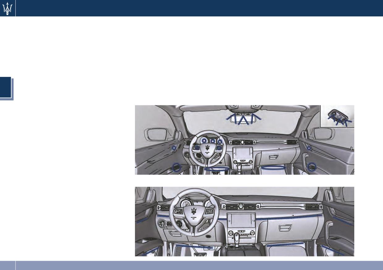
Courtesy Dimmable Lights
• front footrest light;
The following dimmable courtesy
• front seats night lighting.
lights, can be set with the regulation
device:
• instrument cluster dials and display;
• dome light (front/rear);
• inside door handle LED;
• doors and steering wheel backlight
3
controls LED;
108
Understanding the Vehicle
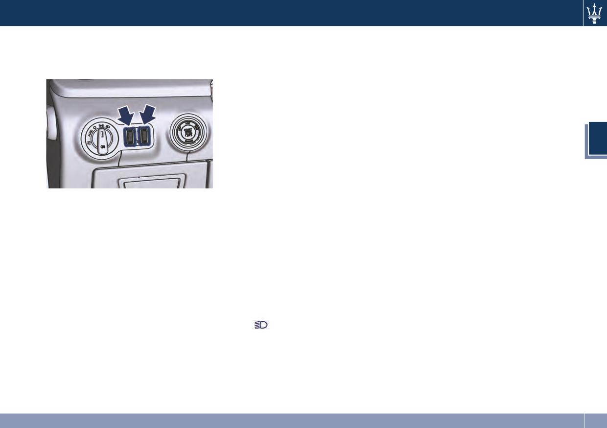
Dimmer Controls
Dome Lights
3rd
Stable position: allows
Dimmer controls are located beside
switching on the main and
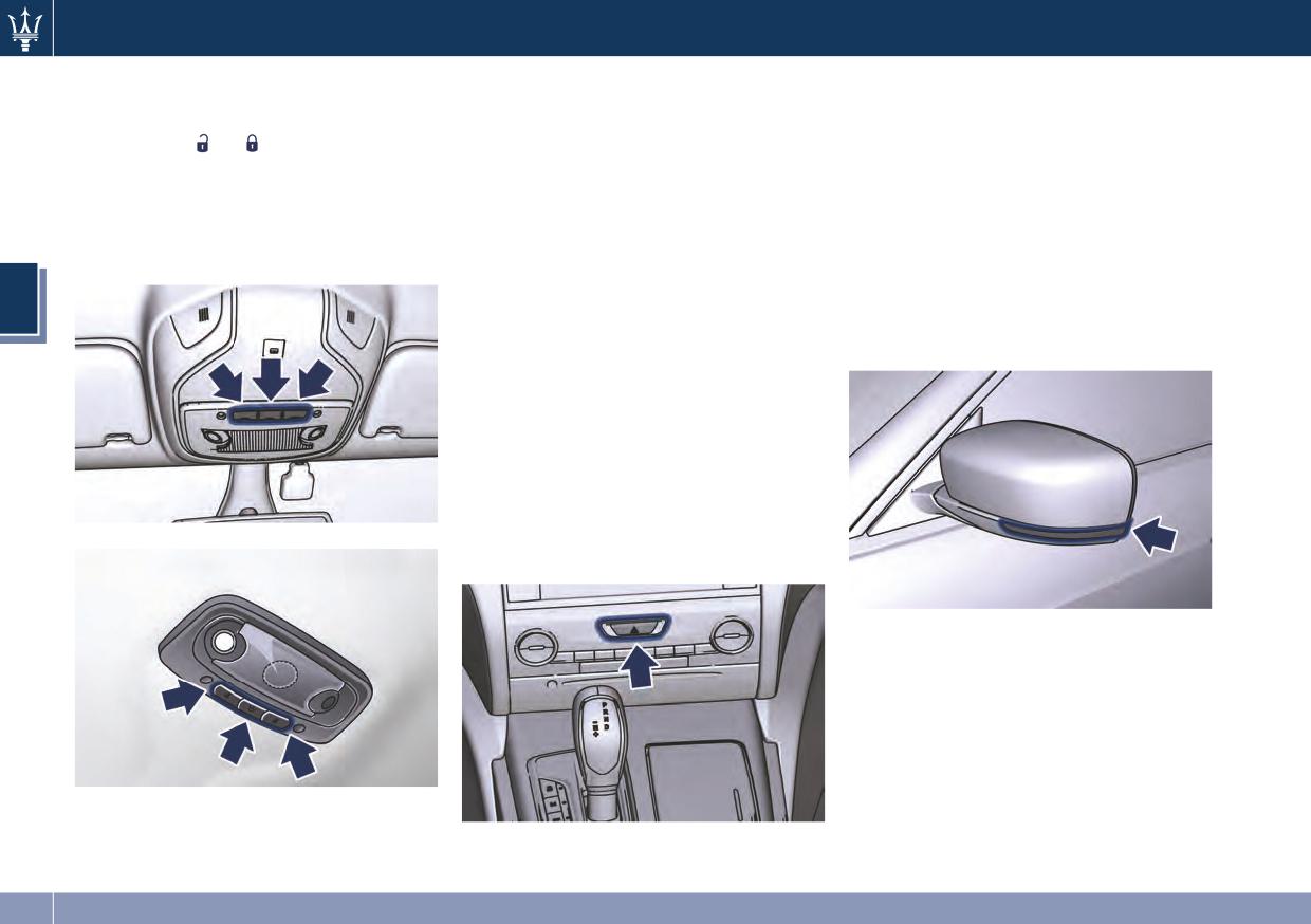
The front and rear part of the dome,
the multifunction light control lever.
the reading lights of the
include each a central and two
front dome light.
reading lights.
The central light automatically turns
on when one of the doors is opened
NOTE:
and turns off when the door is closed
The left regulator operates only with
(timed switching off). The light may be
park lights or low beams lights on.
switched on manually by pressing the
3
central button.
The right regulator has 2 different
The reading lights are controlled by
positions:
the respective side buttons.
0
Stable position: front seat
If they are turned on by pressing the
(OFF)
lighting and front dome light
button, both central and reading
The regulation device rotates from
LED are turned off.
lights will stay on for about 10
position “0” downward and back
minutes after turning the engine off,
upward performing stable and
1st
Dimmable position: allows
and will then turn off gradually.
dimmable positions.
minimum to maximum
When the exterior lights are switched
brightness tuning of the
The left regulator switch has 4
on, the two night LEDs fitted on the
front dome light LED and the
different positions:
side of the buttons will light up to
front seats lighting.
0
Stable position: lower level
facilitate use of the shift lever and the
(OFF)
of the internal lighting.
central console.
NOTE:
If one or more doors are opened, the
1st
Dimmable position: allows
The right regulator is only active if the
front and rear dome lights will turn on
minimum to maximum
switch is in “AUTO” or in low beam
for 27 seconds. If the door is closed
brightness tuning of the
mode
before this time, the lights will dim
instrument cluster dials,
and subsequently switch off after
display, control switches and
about 3 seconds.
MTC’s backlight, including all
displayed messages.
2nd
Stable position: allows
maximum brightness set.
109
Understanding the Vehicle
NOTE:
automatically and remain lit for
Integrated External Rear View
approx. 15 minutes.
The dome lights will also turn on by
Mirror Lights
pressing the
or
button for
NOTE:
Driver and passenger external mirrors
centralized doors unlock and lock on
On the front dome light there are also
are supplied with LED turn signals
the key fob RKE transmitter. See
the sunroof control and the
integrated on the support.
“Illuminated Entry/Exit” section 2 for
HomeLink® controls (if foreseen).
The LED turn signal indicators flash
further information.
simultaneously with the corresponding
turn signal lights in the front and rear
Hazard Warning Flashers
of the vehicle. Turning on the hazard
3
Press the indicated button on the
warning lights will also activate these
center of the control panel to turn on
LEDs.
the hazard warning flashers. The
operation is independent from the
ignition key position.
Press the button again to turn them
off.
When these lights are on, the turn
signals, the related indicator light on
the instrument cluster and the button
itself will flash.
In the event of a collision causing
automatic interruption of fuel supply,
the dome lights switch on
110
Understanding the Vehicle
• To turn the wipers off rotate the
Windshield Wipers and
lever to “OFF”.
Washers
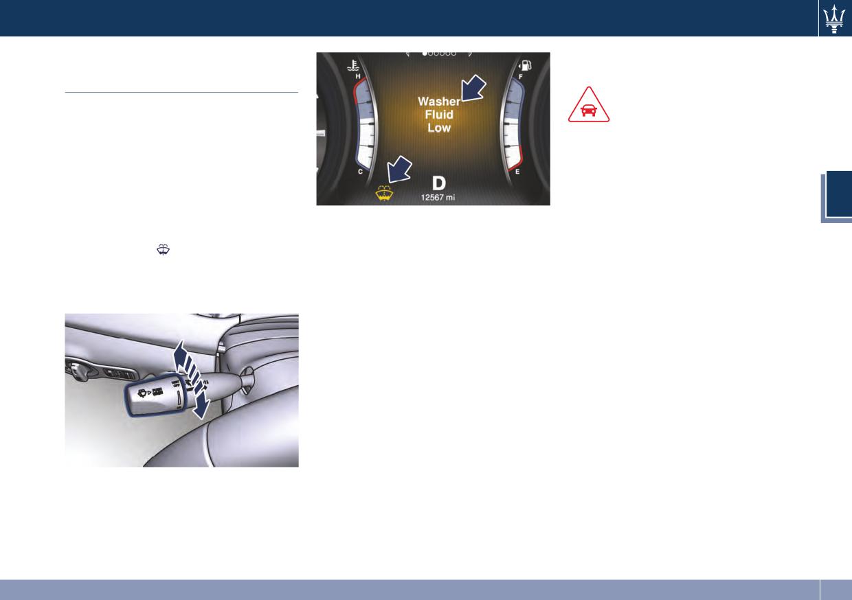
The multifunction lever operates the
CAUTION!
windshield wipers and washer when
the ignition switch is placed in RUN or
• Turn the windshield wipers off when
ACC position. The multifunction lever
driving through an automatic car
is located on the left side of the
wash. The windshield wipers may be
steering column.
damaged if the wiper control is left
3
The headlight and windshield washers
in any position other than “OFF”.
share the same fluid reservoir, and a
Windshield Wipers
• In cold weather, always turn off the
low fluid level is indicated by the same
wiper switch and allow the wipers to
• Rotate the end of the multifunction
indicator light
and by the message
return to the park position before
lever to one of the four settings to
on the instrument cluster.
turning off the engine. If the wiper
activate the automatic intermittent
To refill the fluid, see “Maintenance
switch is left on and the wipers
setting (see “Rain Sensing Wipers”
Procedures” in section 7.
freeze to the windshield, the wiper
paragraph in this chapter).
motor may be damaged when the
• For low speed wiper operation
vehicle is restarted.
(stable position "LO"): rotate the
• Always remove any buildup of snow
end of the multifunction control
that prevents the windshield wiper
lever forward to the first trigger
blades from returning to the off
after the intermittent setting.
position. If the windshield wiper
• Rotate to the second trigger after
control is turned off and the blades
the intermittent setting for
cannot return to the off position, the
high-speed (stable position HI) wiper
wiper motor may be damaged.
operation.
• Rotate the end of the lever
downward to the “MIST” position to
activate a single wipe cycle. The
wipers will continue to operate until
you release the multifunction lever.
111
Understanding the Vehicle
Rain Sensing Wipers
• Use of RainX® or products containing
Headlights On with Wipers
wax or silicone may reduce rain
This feature detects moisture on the
When activating this function, the
sensor performance.
windshield through an internal rear
headlights will light up approximately
view mirror integrated sensor, which
The rain sensing system has protective
10 seconds after the wipers are turned
automatically activates the wipers.
features for the wiper blades and
on if the headlight switch is placed in
Rotate the end of the multifunction
arms. It will not operate under the
“AUTO” position. In addition, the
lever to one of four settings to adjust
following conditions:
headlights switch off when the wipers
the detection system.
are turned off (position “OFF”) if they
• Low Temperature Wipe Inhibit: the
Wiper delay position 1 is the least
were previously turned by using this
3
rain sensing feature will not operate
sensitive, and wiper delay position 4 is
function. Powering on Headlights with
when the ignition is in RUN position,
the most sensitive. Setting 3 should be
wipers can be activated and
the vehicle is stationary and the
used for normal rain conditions.
deactivated with the MTC System, see
outside temperature is below 32 °F
The rain sense wipers will
“MTC Settings” in section 4 for further
(0°C), To resume, set the automatic
automatically change between an
information.
feature on the multifunction lever,
intermittent wipe, slow wipe and a
start the engine and drive or wait
Wipers Blades Maintenance
fast wipe depending on the amount of
until the outside temperature rises
detected moisture sensed by a
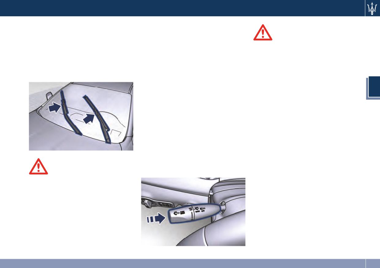
When the wiper arms are in “P” (park
above freezing.
particular area of the windshield.
position) it is not possible to check or
• Neutral Wipe Inhibit: the rain sensing
Place the wiper switch in the “OFF”
replace the blades (Service position) as
feature will not operate when the
position when you do not want to use
they are folded under the hood. To
ignition is placed in the RUN
the automatic intermittent system.
service the blades it is necessary to
position, the transmission shift lever
The rain sensing feature can be turned
shift the multifunction lever to “OFF”
is in the N (Neutral) position and the
on and off using the MTC System, see
and the ignition switch to OFF
vehicle speed is less than 5 mph
“MTC Settings” in section 4 for further
position.
(8 km/h). To resume, set the
information.
Shift the control lever within 15
multifunction lever to the automatic
seconds to the “MIST” panic position
function or move the shift lever out
(counterclockwise rotation of the twist
CAUTION!
of N (Neutral).
switch) and release. The blades are
• The rain sensing feature may not
brought in a position enabling the
function properly with ice or dried
opening of the wiper arms and change
salt water on the windshield.
of the blades. It is possible to use the
panic position for a maximum of 3
112
Understanding the Vehicle
times within two minutes,
Windshield and Headlight
corresponding to different the blades
Washers
WARNING!
positions on the windshield. When
To use the washer, push the end of the
• Do not start the windshield washer
completed bring the ignition switch in
multifunction lever inward (toward
during the cold months until the
RUN: the arms will reposition. If
the steering column) and hold it as
windshield has warmed up. If it has
necessary move the multifunction
long as washer spray is desired.
not warmed up, the liquid could
lever to other required operating
If you activate the washer while the
freeze on the glass and block your
positions.
windshield wiper control is in the
view.
automatic intermittent range, the
• Sudden loss of visibility through the
3
wipers will operate for two wipe
windshield could lead to a collision.
cycles after releasing the lever and
You might not see other vehicles or
then resume the previously selected
other obstacles. To avoid sudden
intermittent interval.
icing of the windshield during
If you activate the washer while the
freezing weather, warm the
windshield wiper is turned off (OFF)
windshield with the defroster
the wipers will operate for three wipe
before and during windshield
cycles and then turn off.
washer use.
At low external temperatures, the
fluid supply nozzles are heated by
The multifunction lever also operates
internal resistors to avoid fluid
the headlight washers when the
WARNING!
freezing inside.
ignition switch is in RUN position and
the headlights are turned on.
Operate or service the wiper blades
The headlight washers will spray a
without deactivating the wipers
timed high pressure spray of washer
(“OFF” position) leaving the ignition
fluid onto each headlight lens every
switch in RUN can be dangerous for
11 windshield wipers cycles.
the operator since the rain sensor may
suddenly activate the wipers. Always
use “Service” position for any
intervention on the wiper blades.
113
Understanding the Vehicle
any other object in the power outlets
Interior Features
as this will damage the outlet and
WARNING!
blow the fuse. Damages caused by
Electric Power Outlets
improper use of the power outlet are
High power consumption items
The vehicle is equipped with three
plugged into this outlet for long
not covered by the New Vehicle
12 Volt (13 Amp) electric power
periods may discharge the battery
Limited Warranty.
outlets, one available for each front
and/or prevent the engine from
seats, rear seats passengers and one
starting.
fitted in the trunk.
3
In vehicles with “Comfort Luxury” rear
WARNING!
seats, there is an extra 12 V power
To avoid serious injury or death:
outlet inside the rear console storage
• Only devices designed for use in this
compartment and others in the rear of
type of outlet should be inserted
the reclining shelf between the seats.
into any 12 Volt outlet.
All power outlets are supplied only
when the engine is started or the
• Replacing the fuses that protect
ignition device set on ACC or RUN.
power outlets with others of higher
Power outlets are protected by a fuse.
amperage, there is the risk of fire.
Insert a cigar lighter or accessory plug
• Do not touch with wet hands.
into the power outlets to ensure
• Close the lids when the plug is not
proper operation. Otherwise, check
used and while driving the vehicle.
the matching fuse integrity, see “Fuse
• If this outlet is mishandled, it may
Replacement” in section 7 for further
cause an electric shock and failure.
information.
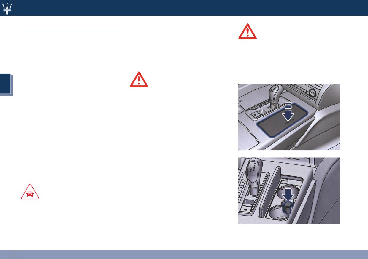
Power Outlet inside the Cup Holder
CAUTION!
To access the power outlet inside the
cup holder beside the shift lever, press
• Do not plug in accessories that
the cover as indicated to open
exceed the maximum power of 160
completely.
Watts (13 Amps) at 12 Volts or 150
Watts at 115 Volts.
• Power outlets are designed for
accessory plugs only. Do not insert
114
Understanding the Vehicle
Power Outlets inside the Central
Console
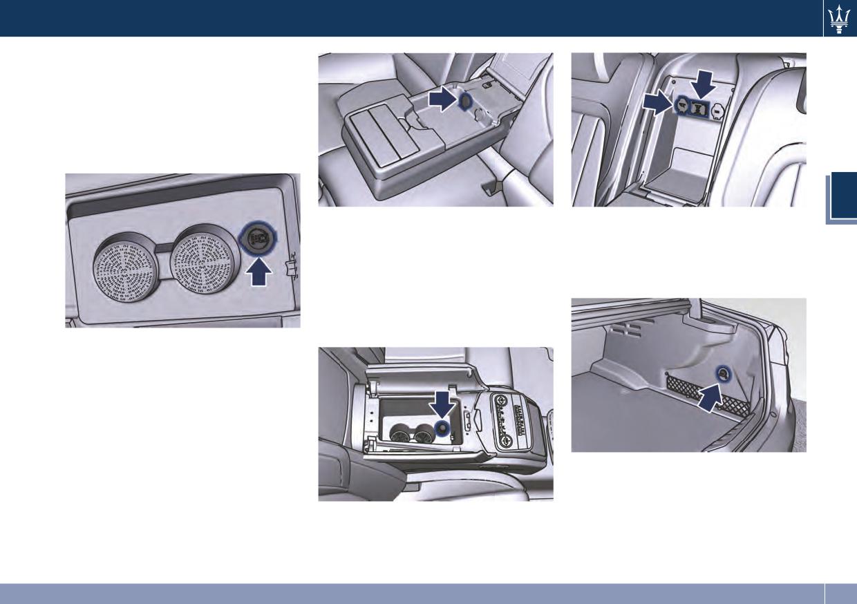
To access the power outlet located
inside the glove box of the central
console you need to open the half-lids
as indicated in the following
paragraph.
3
A 12 V power outlet both inside the
“Comfort Luxury” Rear Seats
central console and in the rear of the
Power Outlet inside the Trunk
reclining shelf, are available for rear
seats passengers (see “Comfort Luxury
The power outlet is positioned on the
Rear Seats” in this section).
right side of the trunk.
In the rear of the reclining shelf, on
request, can be installed a 115 V - AC
(150 W) power outlet.
Rear Power Outlets
If the vehicle is equipped with bench
seats, a 12 V power outlet inside the
armrest between the seats, is available
for rear seat passengers (see “Rear
Seats” in this section).
“Comfort Luxury” Rear Seats
115
Understanding the Vehicle
Cup Holders
The vehicle is equipped with several
cup holders.
CAUTION!
• Use light and shatterproof
containers.
3
• Do not forcefully push unsuitable
containers into the cup holders to
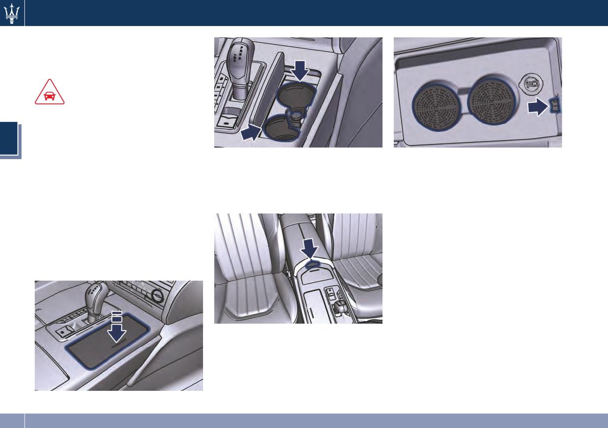
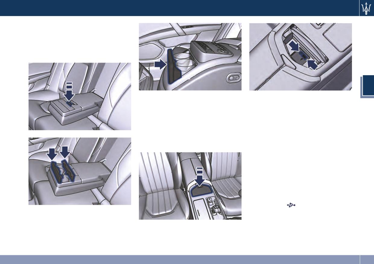
Pressing the indicated button, the
To close one or both of the half-lids,
prevent damage to the containers.
half-lids will rise completely enabling
push them down to the locking
• Do not store hot drinks.
access to the inner compartment
position.
where the two cup holders are
Front Seats Cup Holders
NOTE:
located.
The front cup holders are located
Vehicles equipped with the four-zone
within the central console beside the
air conditioning system, are not
transmission shift lever.
equipped with cup holders inside the
To access the cup holder, push the lid
central console.
as shown in the picture and it will
open completely.
The storage and passenger
compartment share the same air
conditioning even though you may
exclude the air conditioning of the cup
holder compartment by moving the
indicated button.
116
Understanding the Vehicle
Rear Seats Cup Holders
Two cup holders are available in the
frontside of the rear seats central
armrest, press the button as shown in
the picture to access them.
3
“Comfort Luxury” rear seats
The AUX auxiliary port features:
• typical input impedance between
AUX and USB Port
AUX-IN and AUX_REF: 13 Kohm;
The AUX and USB ports are located
• max. applicable voltage: 0.75 Vrms at
inside the compartment behind the
1 kHz;
transmission shift lever. To access the
• input compatible only with 3.5 mm
ports, push the lid as indicated: it will
jack connectors (not included).
open completely.
Any player with these characteristics
and analog audio output (headset
output type) can be served by the MTC
System. The system can recognize the
connection to a player outlet
autonomously enabling access to the
audio functions connected to this
source.
The USB port
, available by
On vehicles equipped with the
removing protection cap, allows the
“Comfort Luxury” rear seats, the cup
data exchange and charge of the
holders are located in the front and
connected source. If there are MP3
rear central storage compartment (see
files on the USB device, they will
“Comfort Luxury Rear Seats” in this
automatically start playing.
section for further information).
117
Understanding the Vehicle
If you are already listening to music
from a different source you need to
CAUTION!
select the USB function to start playing
audio contents (refer to the MTC
Do not leave your USB device, iPod® or
guide).
an external audio source in the vehicle
for extended period of time: extreme
NOTE:
temperatures and humidity can occur
• Another USB port is present inside
in the vehicle.
the armrest between the rear bench
3
seats.
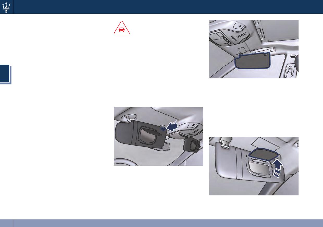
Sun Visors
• Optional “Comfort Luxury” rear seats
Sun visors can be folded to the front
By lowering the visor on the
are equipped with a USB port
and to the side of the vehicle. To move
passenger's side you can access the
beneath the reclining shelf between
the visor laterally, lower and release it
courtesy mirror with incorporated light
the seats (see “Comfort Luxury Rear
from its catch as indicated.
illuminating automatically (with the
Seats” in this section).
ignition switch in RUN) by raising the
• The "Rear Seat Entertainment"
mirror protective cover. Before raising
option, includes a AUX and a USB
the visor, close the mirror cover.
port in the rear of each front seat
A paper holder is fitted inside each sun
(see “Interior Features” in this
visor.
section).
iPod® Connection
An iPod® can be connected to the
system via USB and AUX ports by
means of a special cable (optional).
The MTC will then control the
following functions: play, pause, fast
forward, rewind, next track, previous
track, random or repeat mode,
selection and navigation of
playlist/genre/singer/album/Podcast.
118
Understanding the Vehicle
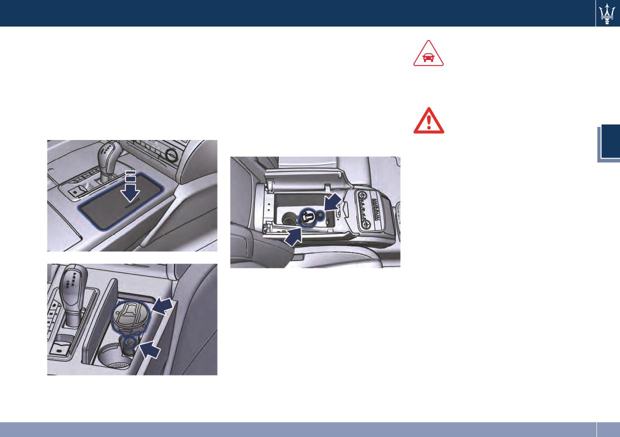
Smoking Kit (optional)
The rear seat passengers can use the
removable ashtray by inserting it into
The kit includes a lighter and a
CAUTION!
the rear doors pocket, while the
removable ashtray with cover.
lighter can be inserted into the power
After use, always make sure that the
The Smoking kit for front seats
outlet inside the armrest between the
cigarette lighter is switched off.
passengers is located inside the box
rear seats.
beside the transmission shift lever and
On vehicles equipped with rear seats
can be accessed by pressing the cover
“Comfort Luxury” Smoking kit, lighter
as indicated.
WARNING!
and ashtray are fitted inside the
center console between the seats.
• The cigarette lighter reaches high
3
temperatures. Handle it carefully
and do not allow children to use to
avoid risk of fire and injury!
• The cigarette lighter outlet may not
be used as a power.
“Comfort Luxury” Rear Seats
Pressing the central button activates
the cigarette lighter. After about 20
seconds the button returns
automatically to the initial position
and stops the heating: now the
cigarette lighter is ready for use.
119
Understanding the Vehicle
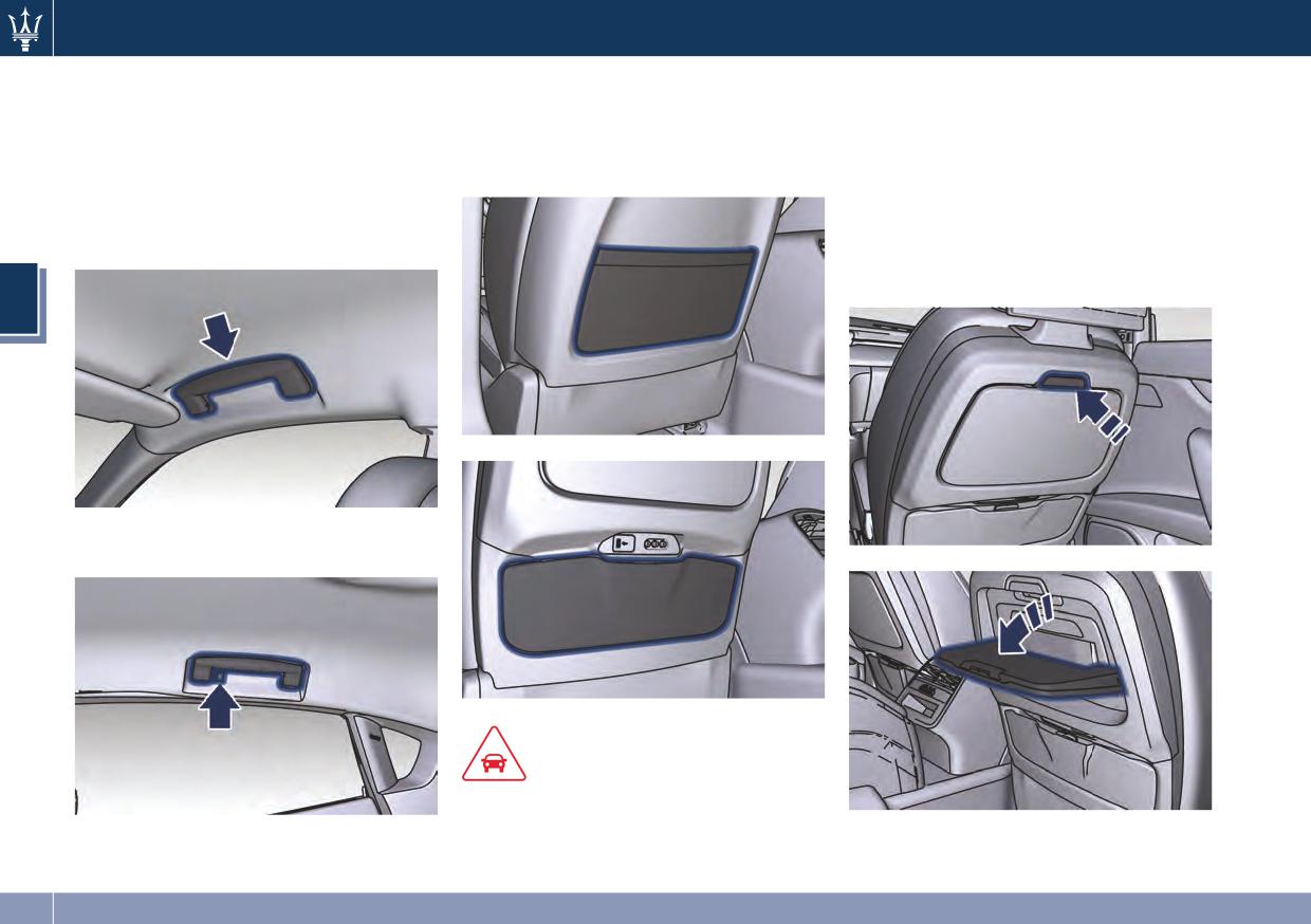
Handholds and Cloth Hooks
Map Pockets
Tables (optional)
Handholds are fitted above the
Front seats are fitted with map
Tables are fitted in the back of the
passenger doors. Once grabbed, they
pockets, on the rear of the seatbacks,
front seats.
will lower until the block position.
and accessible by rear passengers.
• Opening: press the upper button and
When released, a return spring will
lower the table until the supporting
bring them back to the original
mechanism snap locks.
position.
• Closing: lift the table until the upper
button snap locks.
3
Rear handholds also include a clothes
hook.
CAUTION!
Do not put heavy or sharp objects in
the map pockets.
120
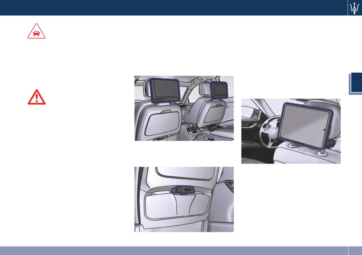
Understanding the Vehicle
Rear Seat Entertainment
See the user guide provided with the
vehicle documentation.
(optional)
CAUTION!
As the table is not equipped with cup
This optional includes the installation
iPad Holder (Genuine
holders, do not place open drinks
of a screen in the rear of each front
Accessory)
containers on the tables during the
seatback and a remote control to
The Authorized Maserati Dealer can
journey in order not to damage or
connect with an external video source
provide you with all information
stain the surrounding upholstery if
and any audio devices.
about the “Maserati iPad Holder”
they fall over.
mounted on the rear of the front
seatbacks, available in the Genuine
3
Accessories range.
WARNING!
• When the table is not used, it should
be closed to prevent rear seat
passengers from being hit by its
edges and corners.
• When closing the table, hold it up
carefully in order to avoid pinching
Inside the map pocket on the rear of
your fingers.
the seat-back there are two leds to
illuminate the RSE system outlets.
121
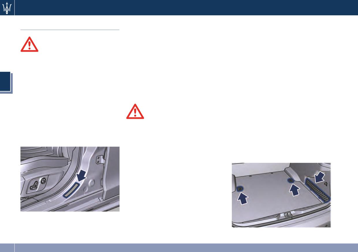
Understanding the Vehicle
Do not exceed the specified Gross
The trunk is the most suitable place to
Cargo Area
Vehicle Weight Rating (GVWR) or the
load bulky and heavy objects onboard
Gross Axle Weight Rating (GAWR)
the vehicle. The maximum allowable
front and rear.
load on the floor of the trunk is 440 lb
WARNING!
The GVWR is the total allowable
(200 kg).
To help protect against personal injury,
weight of your vehicle. This includes
To load your vehicle properly, store
passengers should not be seated in
driver, passengers, and cargo.
heavier items below and be sure you
the rear cargo area. The rear cargo
The total load must be limited so that
distribute their weight as evenly as
space is intended for load carrying
you do not exceed the GVWR
possible.
3
purposes only, not for passengers,
indicated on the label.
Stow all loose items securely before
who should sit in seats and use seat
you start driving as they could move
Vehicle Loading
belts.
during the trip.
Light objects can be stored in the net
Vehicle Load Carrying Capacity
pocket on the right side of the trunk.
WARNING!
To fasten heavy and bulky luggage
The load carrying capacity of your
• Improper weight distribution can
inside the compartment a luggage net
vehicle is shown on the vehicle
have an adverse effect on the way
with hooks anchored to the floor is
homologation label positioned on the
the vehicle steers, handles and the
available upon request. The hooking
driver's side rear door pillar.
way the brakes operate.
eyelets of the net are positioned on
the floor and on the rear wall of the
• Never drive with the trunk open.
trunk.
Exhaust gases can enter the
passenger compartment.
• Do not pile luggage or cargo higher
than the top of the seatback. This
could impair visibility or become
dangerous in a sudden stop or
collision.
The information indicated on the label
concerns passengers and luggage
loading operations.
122
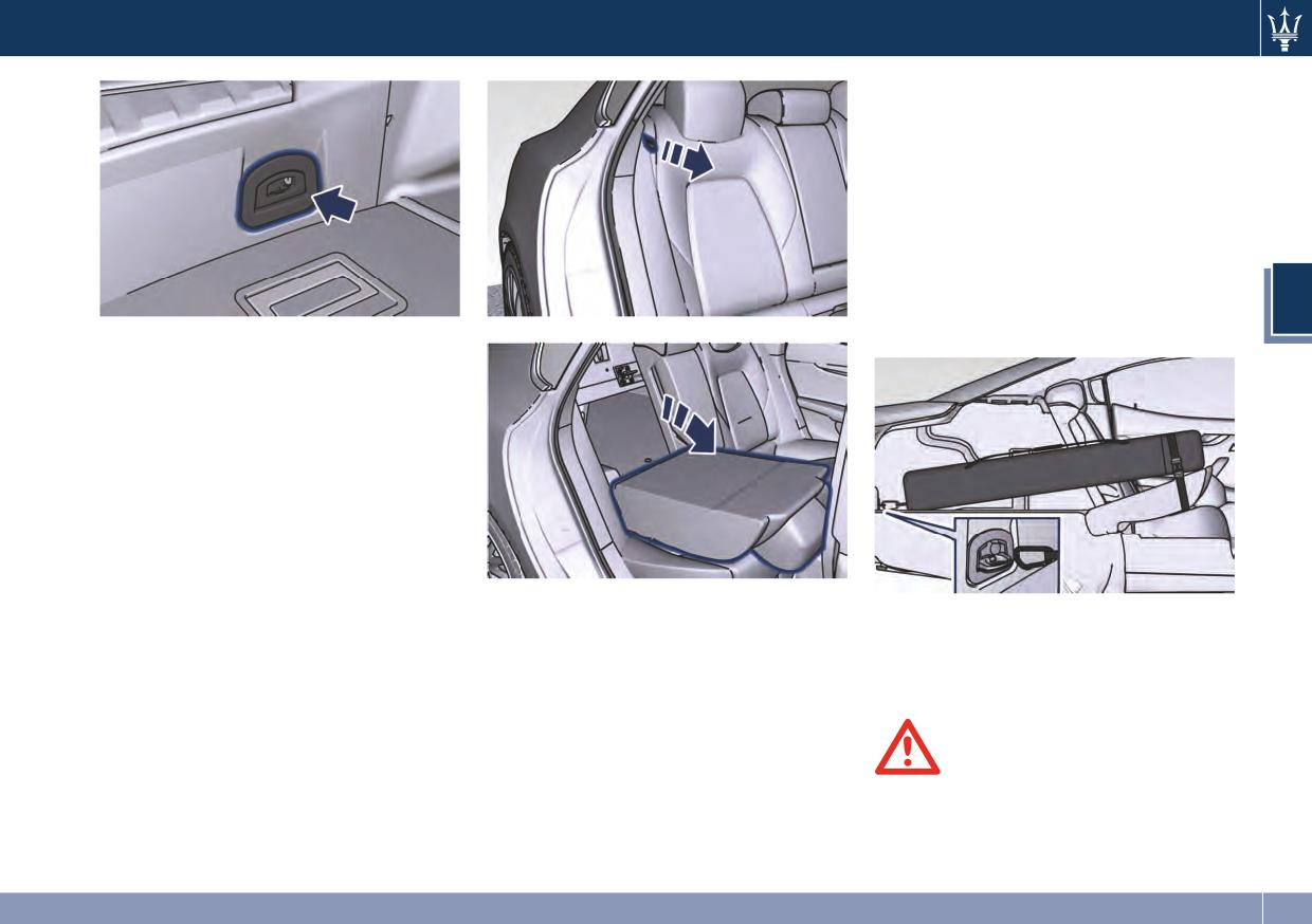
Understanding the Vehicle
NOTE:
To safely store the Ski and Snowboard
Bag, tilt forward the short seatback
side. Secure the rear hook of the bag
to the eyelet located on the rear wall
of the trunk compartment. Wrap the
belt around the seat back of the
folded seat and fasten the belt buckle.
Tighten the belt as much as necessary
3
to prevent the bag from moving.
NOTE:
The Authorized Maserati Dealer can
provide you with information about
the available Genuine Accessories for
the trunk compartment.
Loading with Rear Seatbacks
Down
The 60/40 split-folding rear seat with
folding option on the smaller side
only, provides cargo-carrying
The seat folded down, provides a
When the seatback is folded to the
versatility.
continuous nearly-flat extension of
upright position, make sure it is
The seatback folds down easily by
the load floor able to accommodate
latched by strongly pulling on the top
pulling the tab between the seatback
large sized equipment and objects
of the seatback above the seat strap.
and the bolster.
(such as the “Maserati Ski and
Snowboard Bag”) that may not fit
with the normal dimensions of the
trunk.
WARNING!
• Make sure that the seatback is
securely locked into position.
(Continued)
123
Understanding the Vehicle
(Continued)
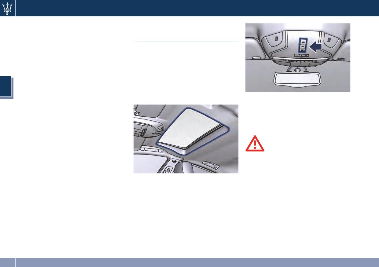
Power Sunroof with
If the seatback is not securely locked
into position, the seat will not
Sunshade
provide the proper stability for child
The sunroof is power controlled and
seats and/or passengers. An
can only be operated with the ignition
improperly latched seat could cause
switch in RUN position. It can slide
serious injury.
lengthways and be raised at the rear
• The cargo area in the rear of the
(tilting).
vehicle with the rear seatbacks in
By opening the sunroof a front flap
3
the folded down position should not
rises automatically in order to deviate
be used as a play area by children
the air flow.
The sunshade can be opened manually.
when the vehicle is in motion. They
However, the sunshade will open
could be seriously injured in a
automatically as the sunroof opens.
collision. Children should be seated
The sunshade cannot be closed if the
and use proper restraint system.
sunroof is open.
WARNING!
• Improper use of the sunroof can be
dangerous, even if it features a
finger-trap prevention system.
Before and during the sunroof
The power sunroof controls are
operation, always make sure that
located between the sun visors on the
passengers are not exposed to the
overhead console.
risk of injuries caused by the moving
roof or by personal objects dragged
or hit by the moving sunroof.
• Never leave children in a vehicle
with the key fob RKE transmitter in
the passenger compartment.
(Continued)
124
Understanding the Vehicle
(Continued)
• Full or partial manual opening
Pinch Protect Feature
• In a collision, there is a greater risk
To open the sunroof manually press
This feature will detect an obstruction
of being thrown from the vehicle if
the rearward button for less than
in the opening of the sunroof during
the sunroof is open. Always fasten
half second to move step by step
express close operation. If an
your seat belt properly and make
the sunroof panel.
obstruction is detected, the sunroof
sure all passengers are properly
will automatically retract. If this
secured too.
Venting Sunroof
occurs, remove the obstruction then
• Do not allow small children to
Press and release the central button,
press the forward button and release
operate the sunroof. Never insert
and the sunroof will open to the vent
to express close.
fingers, other body parts, or any
3
position. This is called “Express Vent”,
object through the opening sunroof.
and will occur regardless of sunroof
NOTE:
position. During this opening
If three consecutive attempts to close
operation, any movement of the
the sunroof result in pinch protect
CAUTION!
button will stop the sunroof.
reversals, the fourth attempt will be
manual, with pinch protect feature
• In the event of rain, always close the
Closing Sunroof
disabled.
sunroof to prevent water
• Full automatic express closing
infiltrations from staining the
Pinch Protect Override
Press the forward button for more
fabric/leather upholstery.
than half second and the sunroof
If any obstruction (ice, debris, etc.)
• Do not open the sunroof if there is
will close automatically regardless
prevents closing the sunroof, press the
ice on it: risk of damage.
of any previous position. The
forward button and hold for two
sunroof will close fully and stop
seconds after the reversal occurs. This
Slide Opening Sunroof
automatically. During this
allows the sunroof to move toward
• Full automatic express opening
operation, if any button is pressed,
the closed position.
the sunroof will stop.
Press the button rearward for more
NOTE:
than half second and the sunroof
• Full or partial manual closing
Pinch protection is disabled while
will open automatically regardless
To close the sunroof manually press
pressing the forward button.
of any previous position. The
the forward button for less than
sunroof will open fully and stop
half second to move step by step
automatically. During this
the sunroof panel.
operation, if any sunroof button is
pressed, the sunroof will stop.
125
Understanding the Vehicle
To Close the Power Sunroof
together to minimize the buffeting. If
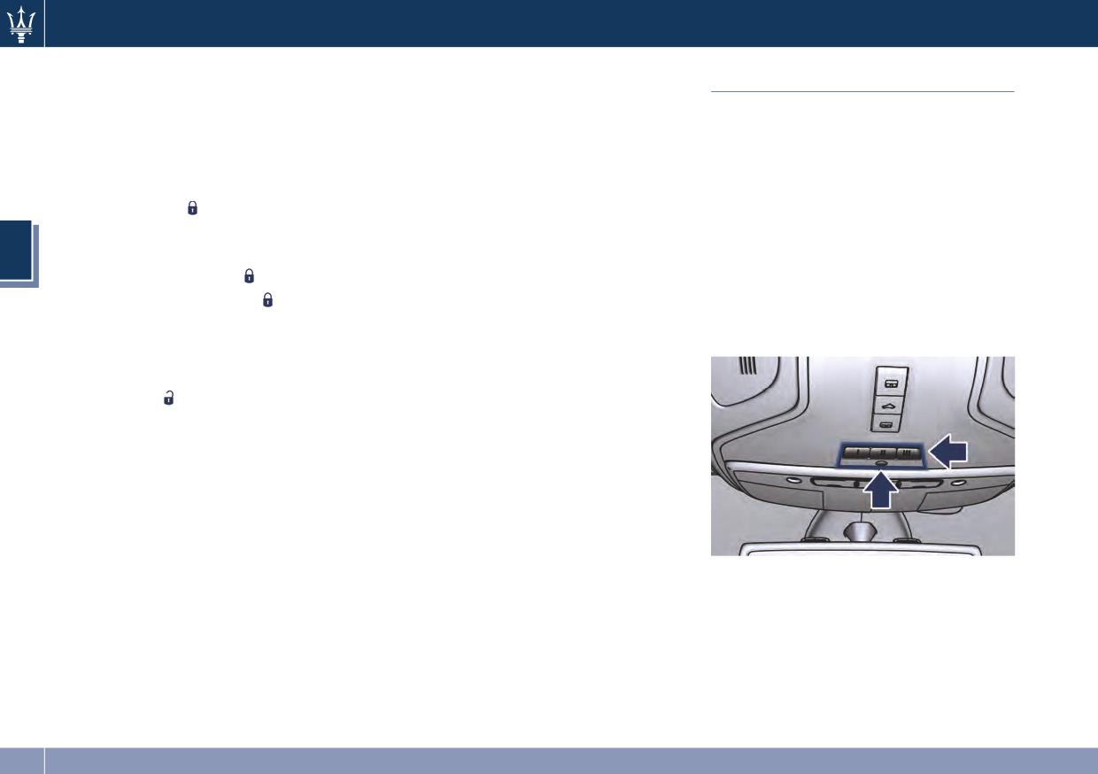
HomeLink® (Optional)
the buffeting occurs with the sunroof
with RKE Transmitter and
open, then adjust the sunroof opening
HomeLink® replaces up to three
Ignition Off
to minimize the buffeting.
hand-held transmitters that operate
When the ignition switch is in OFF
automatic devices that open garage
position, if the sunroof is open, it can
Ignition Off Operation
doors and gates, enable/disable the
be closed together with the windows
The power sunroof controls will
lighting or security systems. The
by pressing the
button on the RKE
remain active for up to approximately
HomeLink® unit is powered by your
transmitter (refer to “Power
ten minutes after the ignition switch is
vehicles 12 Volt battery. The
Windows” in Section 2).
3
in OFF position. Opening either front
HomeLink® buttons that are located in
• Press and release the
button.
door will cancel this feature. The
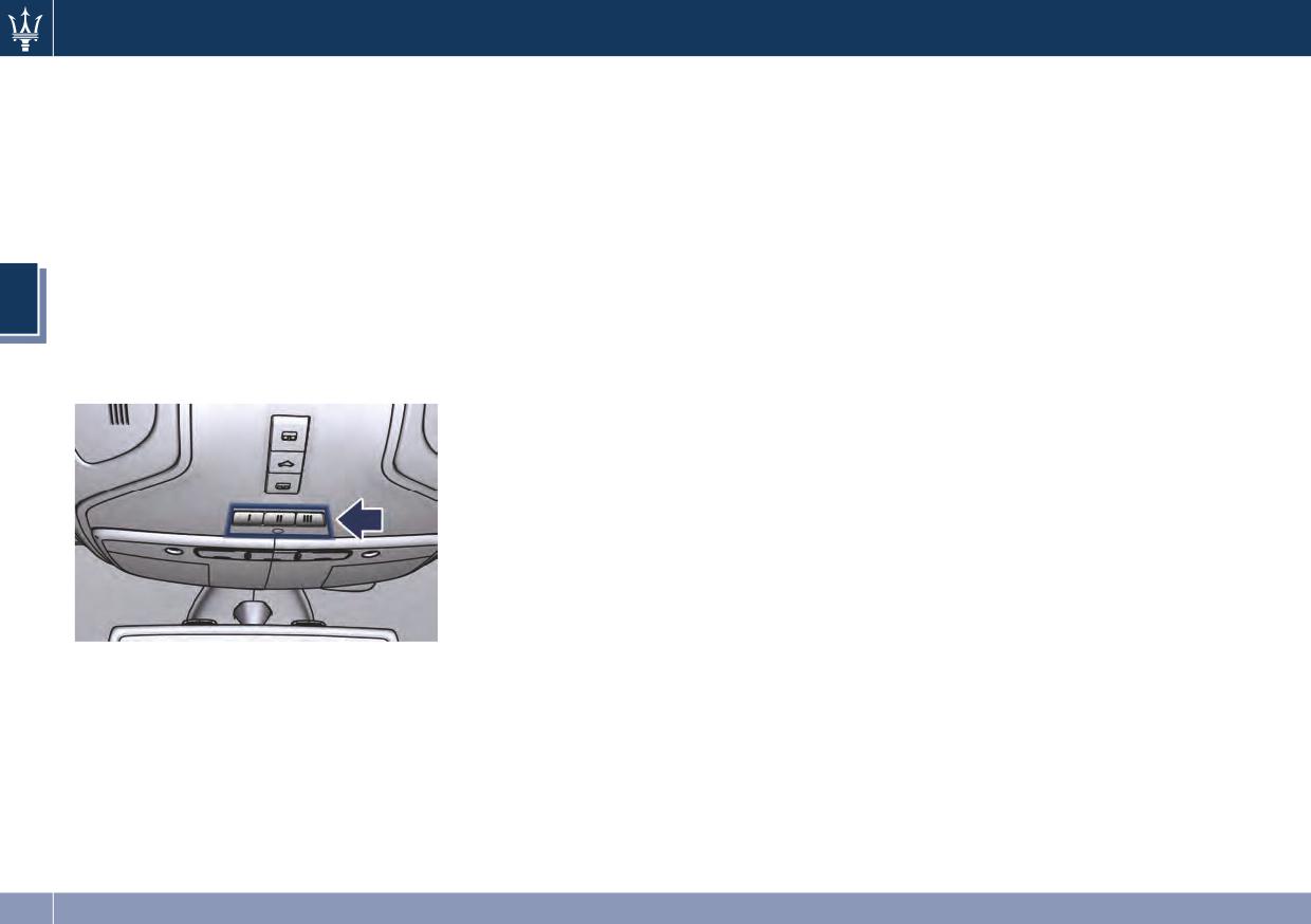
the overhead console designate the
ignition system timing can be set using
three different HomeLink® channels.
• Press a second time the
button
the MTC System (see “MTC Settings” in
The HomeLink® warning light is
and keep it pressed until the sunroof
section 4).
located above the center button.
is completely closed.
NOTE:
Sunroof Maintenance
Pressing the
button on the RKE
Use only a nonabrasive cleaner and a
transmitter will only open the
soft cloth to clean the glass panel.
windows but will have no effect on
the sunroof.
Wind Buffeting
Wind buffeting can be described as
the perception of pressure or a
helicopter-type sound. Your vehicle
NOTE:
may exhibit wind buffeting with the
HomeLink® is disabled when the
windows down, or the sunroof in
vehicle security alarm is active (see
certain open or partially open
“Vehicle security alarm” in section 2).
positions. This is a normal occurrence
and can be minimized. If the buffeting
occurs with the rear windows open,
then open the front and rear windows
126
Understanding the Vehicle
General Information
Before You Start Programming
®
This device complies with FCC rules
HomeLink
WARNING!
Part 15 and Industry Canada RSS-210.
Be sure that your vehicle is parked
• Your motorized door or gate will
Operation is subject to the following
outside of the garage before you
open and close while you are
two conditions:
begin programming.
programming the universal
transceiver. Do not program the
• This device may not cause harmful
For more efficient programming and
transceiver if people, pets or other
interference.
accurate transmission of the
objects are in the path of the door
radio-frequency signal it is
• This device must accept any
or gate. Only use this transceiver
recommended that a new battery be
interference that may be received
3
with a garage door opener that has
placed in the hand-held transmitter of
including interference that may
a “stop and reverse” feature as
the device that is being programmed
cause undesired operation.
required by Federal safety
to the HomeLink® system.
NOTE:
Before starting programming it is
standards. This includes most garage
• The transmitter has been tested and
necessary to erase the standard codes
door opener models manufactured
it complies with FCC and IC rules.
memorized on the HomeLink® device
after 1982. Do not use a garage door
Changes or modifications not
during the production phase. To erase
opener without these safety
expressly approved by the party
such codes:
features. Call toll-free 1-800-355-
responsible for compliance could
3515 or, on the Internet at
• place the ignition device in the RUN
void the user’s authority to operate
www.HomeLink.com for safety
position without starting the engine;
the device.
information or assistance.
• press and hold the two outside
• The term IC before the
• Vehicle exhaust contains carbon
HomeLink® buttons (I and III) until
certification/registration number
monoxide, a dangerous gas. Do not
the warning light starts flashing
only signifies that Industry Canada
run your vehicle in the garage while
(after approximately 20 seconds);
technical specifications were met.
programming the transceiver.
• release the buttons.
Exhaust gas can cause serious injury
or death.
127
Understanding the Vehicle
NOTE:
System with devices provided
has been acquired and programmed
• Erasing the standard codes should
correctly by the HomeLink® system.
with rolling codes
only be performed when
Programming the hand-held
NOTE:
programming HomeLink® for the
transmitters
first time. Do not perform this
• On the last versions of this device it is
For programming garage door/gate
no longer necessary to keep the
operation to program additional
openers that were manufactured after
button on the transmitter and the
buttons.
1995.
HomeLink® buttons pressed; you just
• If you have any problems, or require
These devices can be identified by the
have to release the HomeLink®
assistance, please call toll-free
3
“LEARN” or “TRAIN” setting button
button immediately and keep only
1-800-355-3515 or, on the Internet
located where the hanging antenna is
the first one pressed.
at www.HomeLink.com for
attached to the garage door/gate
information or assistance.
• The distance necessary between the
opener. It is NOT the button that is
portable hand-held transmitter and
normally used to open and close the
the HomeLink® in the vehicle
door.
depends on the system you wish to
The name and color of the button may
program. Probably it will be
vary by manufacturer.
necessary to try several times. Upon
• Place the ignition device to the RUN
every attempt, keep the setting
position without starting the engine.
position for at least 15 seconds
before trying again.
• Place the hand-held transmitter 1 to
3 inches (5 - 30 cm) away from the
Synchronizing the rolling codes
HomeLink® button you wish to
program.
At the end of the previously described
programming, if the HomeLink® has
• Simultaneously press and hold both
been programmed for a rolling code
the Homelink® button you want to
system, it will be necessary to
program and the hand-held
synchronize it to ensure its correct
transmitter button.
operation.
• Continue to hold buttons until the
warning light starts flashing quickly;
• Locate the “LEARN” or “TRAINING”
then release both buttons.
setting button of the opening motor.
The quick flashing light indicates that
Firmly press it and then release it. On
the channel with the new frequency
some garage door openers/devices
128
Understanding the Vehicle
there may be a light that blinks
• Place the ignition device to the RUN
NOTE:
when the garage door opener/device
position without starting the engine.
The distance necessary between the
is in the LEARN/TRAIN mode.
• Press and hold the desired
portable hand-held transmitter and
HomeLink® button.
the HomeLink® in the vehicle depends
NOTE:
• Without releasing the button
on the system you wish to program.
You have 30 seconds in which to
proceed with “Programming the
Probably it will be necessary to try
initiate the next step after the setting
hand-held transmitters” from second
several times. Upon every attempt,
button has been pressed.
step and follow all remaining steps.
keep the setting position for at least
15 seconds before trying again.
• Return to the vehicle and press the
System with devices without
3
programmed HomeLink® button for
rolling code
• Press and hold the programmed
two seconds and then release it.
HomeLink® button.
Programming the hand-held
• Repeat this operation a second time.
transmitters
If the garage door opener/device
If the garage door opening device
activates, programming is complete.
For programming garage door
activates, the programming/
To program the remaining two
openers manufactured before 1995.
synchronization phase is complete.
HomeLink® buttons, repeat each step
• Turn the ignition device to the RUN
for each remaining button. Do not
NOTE:
position without starting the engine.
erase the channels.
If the garage door opening device
• Place the hand-held transmitter 1 to
does not activate, press the button a
Reprogramming a Single HomeLink®
3 inches (5 to 30 cm) away from the
third time for two seconds and then
Button
HomeLink® button you wish to
release it to complete the
To reprogram a channel that has been
program.
programming/synchronization phase.
previously trained, follow these steps:
• Simultaneously press and hold both
buttons until the warning light starts
• Place the ignition device to the RUN
• To program the remaining two
flashing quickly; then release both
position without starting the engine.
HomeLink® buttons, repeat each
buttons.
• Press and hold the desired
step for each remaining button. DO
The quick flashing light indicates that
HomeLink® button.
NOT erase the channels.
the channel with the new frequency
• Without releasing the button
Reprogramming a Single HomeLink®
has been acquired and programmed
proceed with “Programming the
Button
correctly by the HomeLink® system.
hand-held transmitters” from second
To reprogram a channel that has been
step and follow all remaining steps.
previously trained, follow these steps:
129
Understanding the Vehicle
Using HomeLink®
Troubleshooting Tips
To operate, press and release the
If you are having trouble
programmed HomeLink® button.
programming HomeLink®, here are
Activation will now occur for the
some of the most common solutions:
programmed device (i.e., garage door
• Replace the battery in the original
opener, gate operator, security system,
hand-held transmitter.
entry door lock, home/office lighting,
• Press the LEARN button on the
etc.). The hand-held transmitter of the
garage door opener to complete the
device may also be used at any time.
3
training for a rolling code.
Security
• Did you unplug the device for
programming and remember to plug
It is advised to erase all channels
it back in?
before you sell or turn in your vehicle.
If you have any problems, or require
To erase the channels press and hold
assistance, please call toll-free
the two outside HomeLink® buttons (I
1-800-355-3515 or, on the Internet at
and III) until the warning light starts
www.HomeLink.com for information
flashing (after approximately 20
or assistance.
seconds).
The HomeLink® Universal Transceiver is
disabled when the vehicle security
alarm is active (see “Vehicle security
alarm” in section 2).
130
Understanding the Vehicle
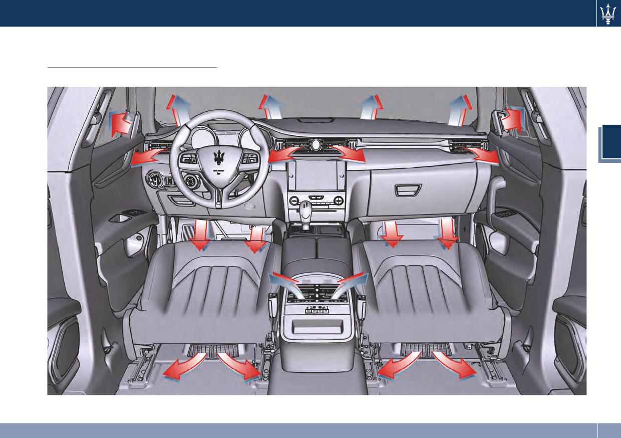
Air Conditioning
Distribution
3
A/C Dual-zone
131
Understanding the Vehicle
3
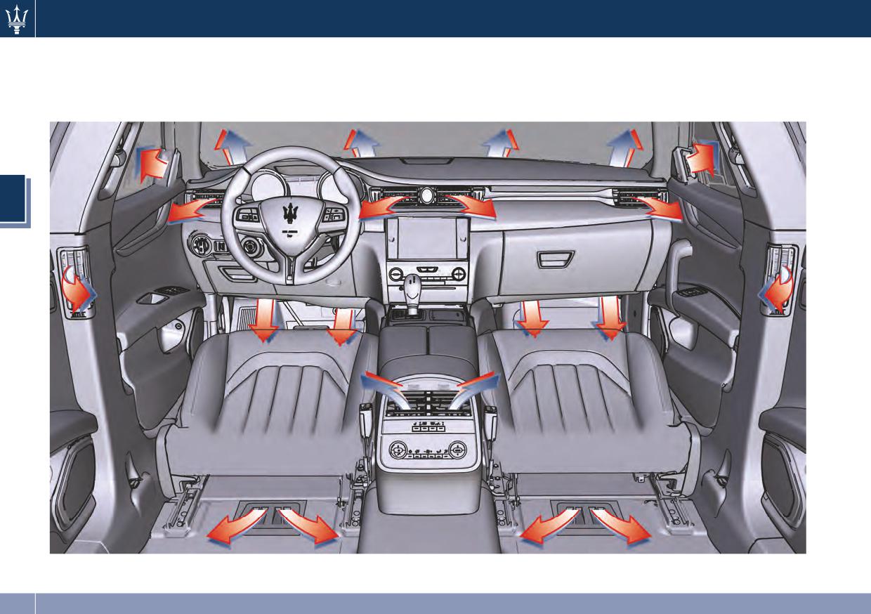
A/C Four-zone
132
Understanding the Vehicle
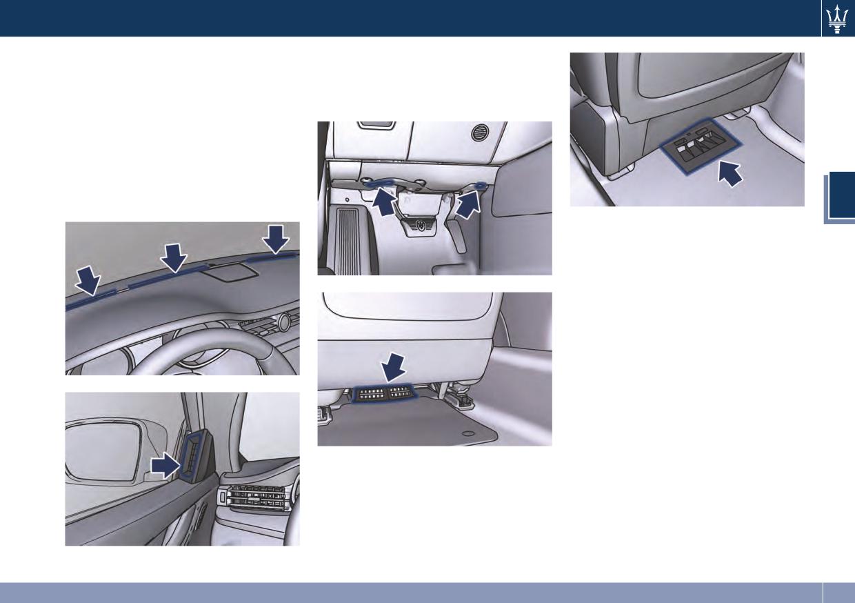
Adjustable and fixed air vents allow
• The fixed vents under the dashboard
Air Conditioning System to achieve
and below the front seats aim to
the optimal comfort conditions.
ventilate the lower part of the
passenger compartment.
• The fixed vents, positioned on the
upper part of the dashboard,
beneath the windshield and above
the front part of the front door
panels are meant to guarantee the
demisting and defrosting of the
3
windshield and the side windows.
A/C Four-zone floor vent
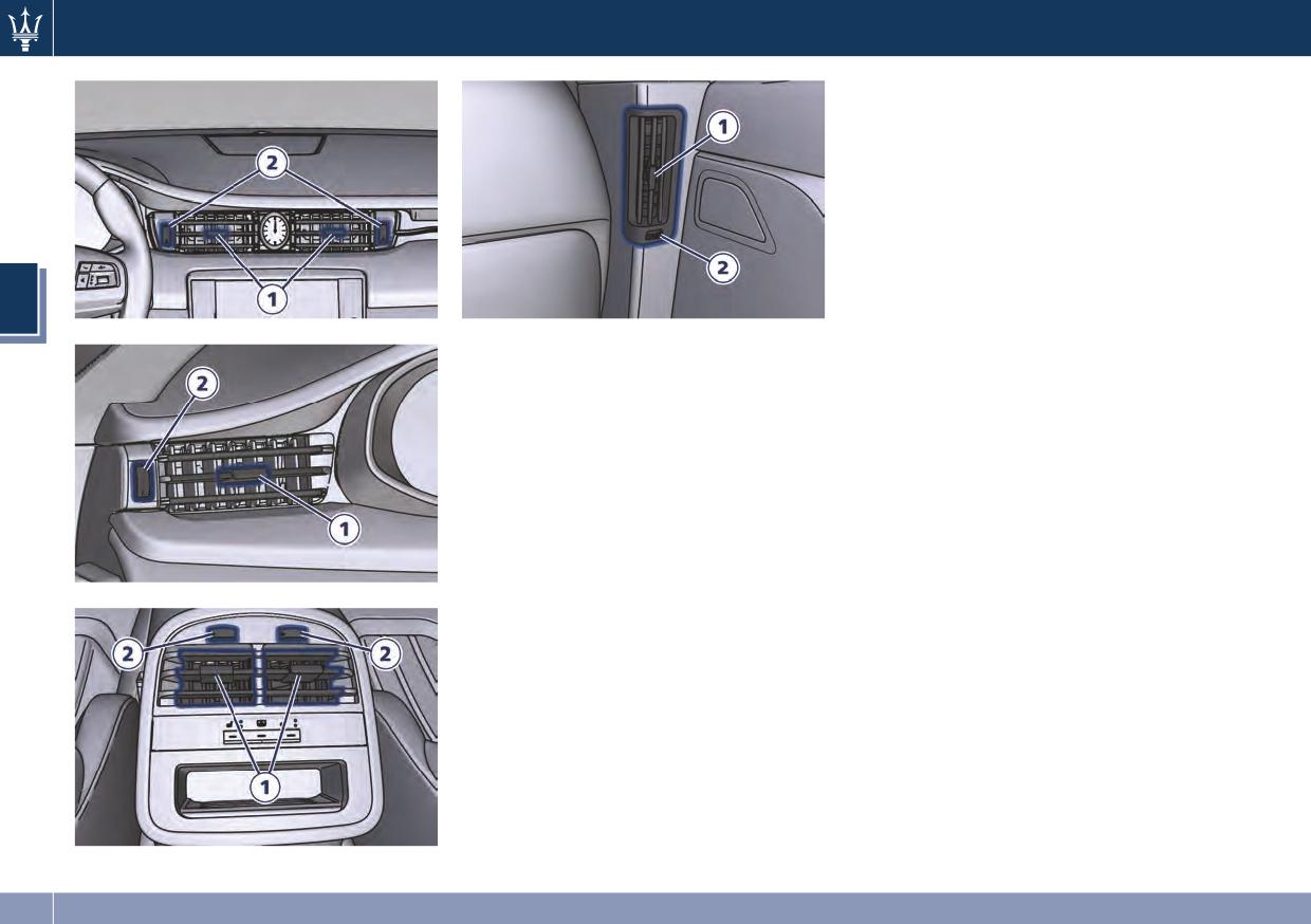
• The adjustable air vents are located
at the center and at the side ends of
the dashboard. They have the
purpose of ventilating the upper
part of the passenger compartment.
Two more vents, adjustable by the
rear passengers, are placed at the
rear end of the central console.
• Optional four-zone air conditioning
provides additional adjustable vents
on the side pillars between the
doors. These vents can be adjusted in
vertical and horizontal direction, by
operating on the central paddle 1, as
A/C Dual-zone floor vent
indicated in the following pictures.
The rotor 2, located near each air
vent, allows to regulate the airflow,
or to close the vent. Orienting these
vents it is also possible to demist the
rear-door windows.
133
Understanding the Vehicle
3
A/C Four-zone side pillar vent
NOTE:
In order to avoid the obstruction of
the windshield defrost vents, it is
recommended not to place objects on
the dashboard.
134
4 - Dashboard Instruments and Controls
Instrument Cluster
136
Infotainment System
157
Audio Controls
159
Audio System
161
MTC Settings
162
Slot for SD Memory Card and CD/DVD
170
Dashboard Compartments
171
Analog Clock
172
Air Conditioning Controls
172
Phone and Voice Controls on Steering Wheel
180
135
Dashboard Instruments and Controls
Instrument Cluster
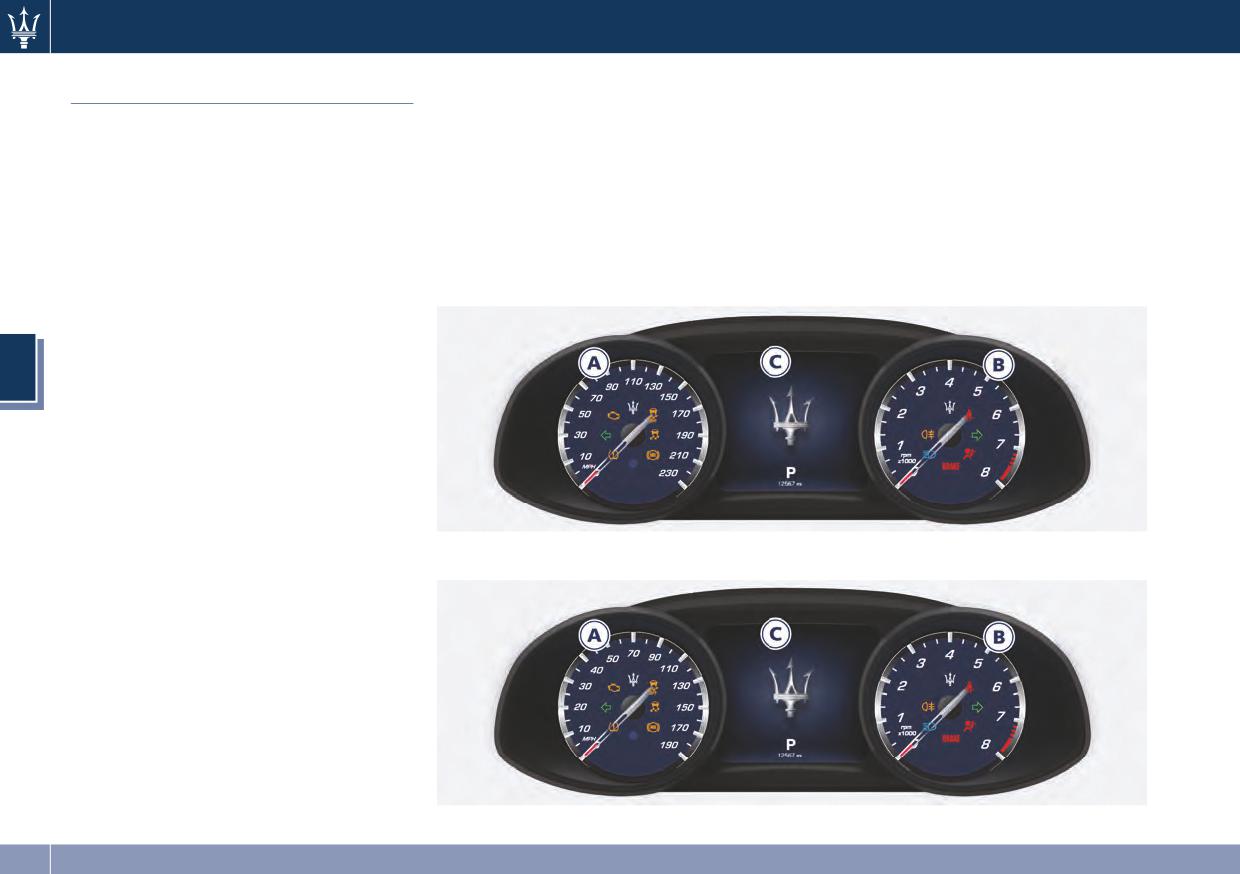
The instrument cluster is divided into
three main areas displaying
information, symbols and text and/or
icon messages.
A. Analogic speedometer. It
indicates the vehicle speed in
MPH.
B.
Rev Counter.
C.
TFT display.
4
NOTE:
The image shows the instrument
cluster before starting the engine.
V8 Engine
V6 Engine
136
Dashboard Instruments and Controls
In the TFT area, the odometer display
Warning Lights on Analog
shows the total distance the vehicle
Instruments
has been driven.
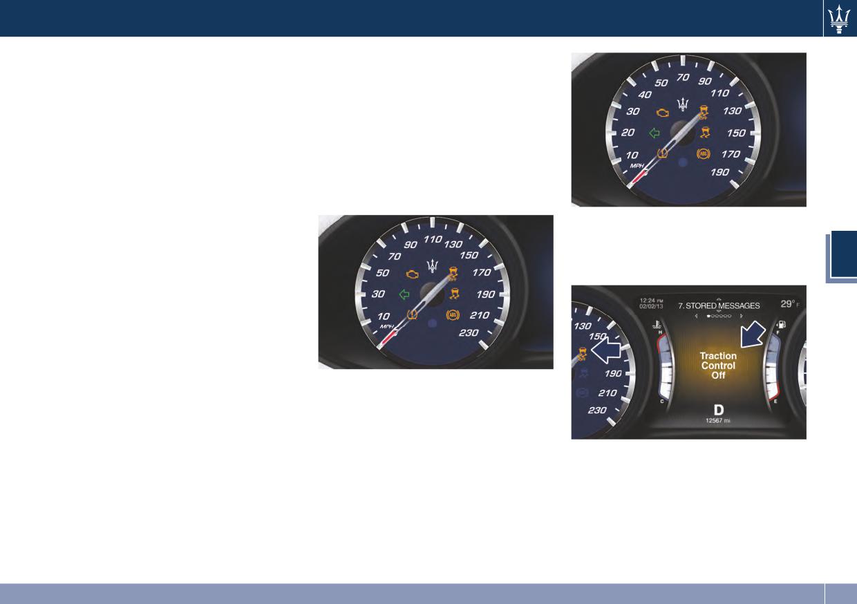
Warning Lights on Speedometer
U.S. Federal Regulations requires that
upon transfer of vehicle ownership,
The following warning lights are
the seller certify to the purchaser the
displayed on the speedometer, and
correct mileage that the vehicle has
related messages are visible for 5
been driven.
seconds on sector 1 of the display,
If your odometer needs to be repaired
unless otherwise indicated (see “TFT
or serviced, the repair technician
Display” paragraph in this chapter).
should leave the odometer reading
V6 Engine
the same as it was before the repair or
Malfunction warning messages will be
service. This repair should be
stored in “Stored Messages” (see
4
performed by an Authorized Maserati
example in picture).
Dealer.
The odometer setting should be
maintained following the repair or
service.
Keep a record of the odometer
mileage before any repair or service to
ensure that the odometer is properly
V8 Engine
reset.
Speedometer and Rev Counter display
the main warning lights (see “Warning
Lights on Analog Instruments” in this
chapter). The other warning lights are
displayed in the lower part of the TFT
display (see “Warning Lights on
Display” in this chapter).
137
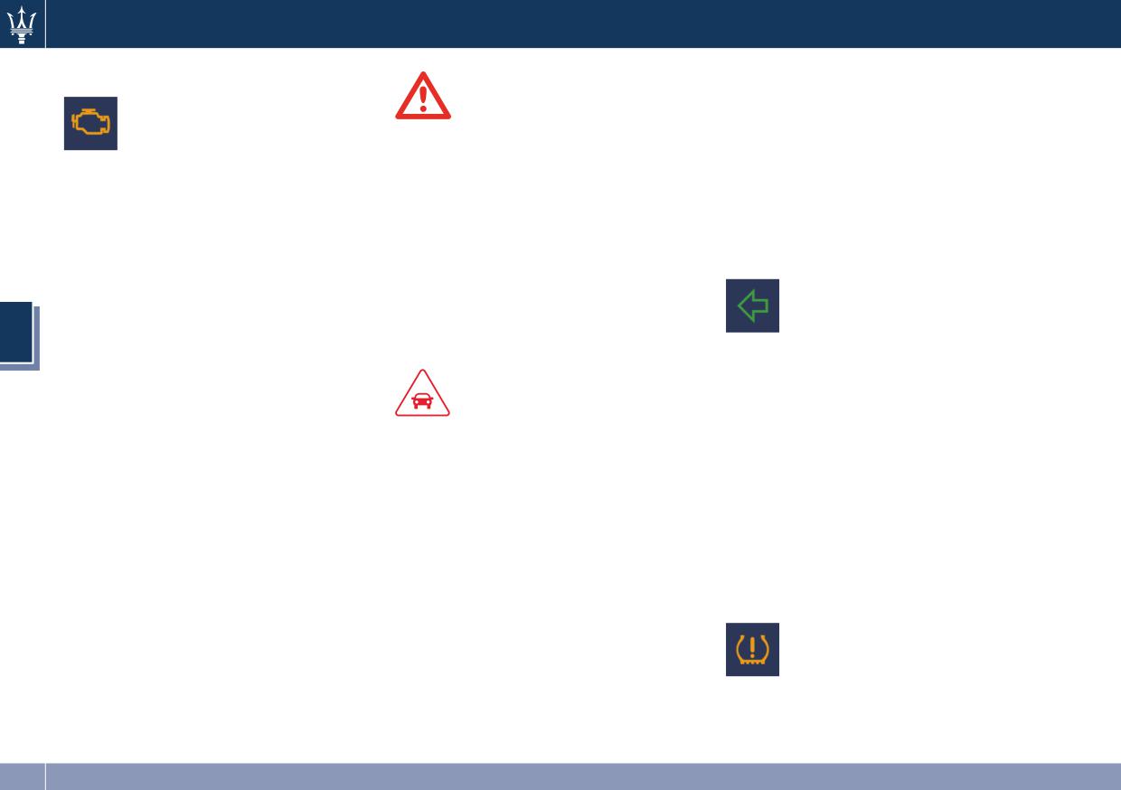
Dashboard Instruments and Controls
Malfunction Indicator Light (MIL)
connector that can be interfaced
using diagnostic equipment. This
The Malfunction Indicator
WARNING!
makes it possible to read the error
Light (MIL) is part of an
Engine exhaust, some of its
codes stored in the control unit,
onboard diagnostic system,
constituents, and certain vehicle
together with a set of specific
called OBD II, that monitors
components contain or emit chemicals
parameters for the engine operation
engine and automatic transmission
known to the State of California to
diagnostic cycle, for compliance with
control systems.
cause cancer and birth defects or other
CARB & EPA OBDII regulations.
Under normal conditions, this indicator
reproductive harm. In addition, certain
should illuminate when the ignition
fluids contained in vehicles and certain
Left Turn Signal Indicator Light
switch is in RUN position and switch
products of component wear contain
off once the engine has been started
The indicator lights up when
or emit chemicals known to the State
(the MIL does not shut off
the left turn signal or the
of California to cause cancer and birth
immediately).
hazard flashers are turned on.
4
defects or other reproductive harm.
This is a sign of the indicator light
The indicator light will flash at
working properly. If the indicator
the same frequency of the turn signals
remains lit or switches on while
and is controlled by the stalk switch
CAUTION!
lever.
driving, there is a failure in the fuel
supply/ignition and emission control
If the vehicle electronics sense that the
• When the ignition switch is in the
systems.
vehicle drives for more than 1 mile
RUN position and if the indicator
The failure could cause high exhaust
(1.6 km) with either turn signal on, a
light does not switch on or if it
emissions, loss of performance, poor
continuous sound will alert the driver
switches on while driving, contact
vehicle handling and high fuel
to turn the signal off.
the Authorized Maserati Dealer as
consumption levels.
If the indicator flashes at a rapid rate,
soon as possible.
Should this occur, proceed with
check for a defective exterior light
• Prolonged driving with the MIL on
caution to your Authorized Maserati
bulb.
could cause damage to the engine
Dealer without heavy throttle
Tire Pressure Monitoring Light
control system. It also could affect
application or driving at high speeds.
fuel economy and drivability. If the
This warning light is connected
Obey all applicable local traffic
MIL is flashing, severe catalytic
to the Tire Pressure
regulations.
converter damage and power loss
Monitoring System (TPMS).
The indicator light will go out if the
will soon occur. Immediate service is
Under normal conditions, the
problem is no longer present.
required. In addition, the OBDII
warning light should illuminate when
The error will be registered by the
system incorporates a diagnostic
the ignition switch is in RUN and
system in any case.
138
Dashboard Instruments and Controls
should go off once the engine is
light remains lit or turns on while
NOTE:
started.
driving, the Anti-Lock portion of the
Each time the ignition switch is in
If the warning light remains lit or
brake system is not functioning and
RUN:
illuminates while driving, the pressure
requires service. However, the
• The ESC off indicator light and the
of one or more tires is too low and a
conventional brake system will
ESC activation/malfunction indicator
message will be displayed.
continue to operate normally if the
light illuminates temporarily.
The TPMS malfunction indicator is
warning light is switched off. If
• When the ESC is functioning, the
connected to the low tire pressure
the ABS light turns on while driving,
system will make buzzing or clicking
monitoring light.
or if it does not switch on when the
sounds. This is normal. The sounds
When the system detects a
ignition switch is in RUN position,
will stop once ESC becomes inactive
malfunction, the monitoring light and
please visit an Authorized Maserati
and the road conditions that caused
the related message will flash for
Dealer as soon as possible to restore
the ESC activation no longer persist.
approximately one minute and then
the Anti-Lock brake function.
4
remain lit.
Electronic Stability Control (ESC)
Electronic Stability Control (ESC) OFF
This sequence will continue upon
Activation/Malfunction Indicator Light
Indicator Light
subsequent vehicle startups as long as
The ESC activation/
the malfunction lasts.
This light indicates that the
malfunction indicator light on
When the malfunction indicator lights
Electronic Stability Control is
the instrument cluster will
up, the system may not be able to
disabled. The related message
display when the ignition
detect or signal low tire pressure
will be displayed.
switch is in RUN position.
correctly.
It should switch off by starting the
Please refer to “Tire Pressure
engine.
Monitoring System (TPMS)” in section
If the light stays on with the engine
5 for further information.
running, there is a malfunction in the
Anti-Lock Brake (ABS) Light
ESC system.
This light, and its related
If the light still stays on after several
message, indicate possible
ignition cycles, and the vehicle has
malfunctions of the Anti-Lock
been driven for several kilometers at
Brake System (ABS).
more than 30 mph (48 km/h) speed,
The light will turn on when the
visit an Authorized Maserati Dealer as
ignition switch is in RUN position and
soon as possible to have the problem
may stay on for 4 seconds. If the ABS
diagnosed and serviced.
139
Dashboard Instruments and Controls
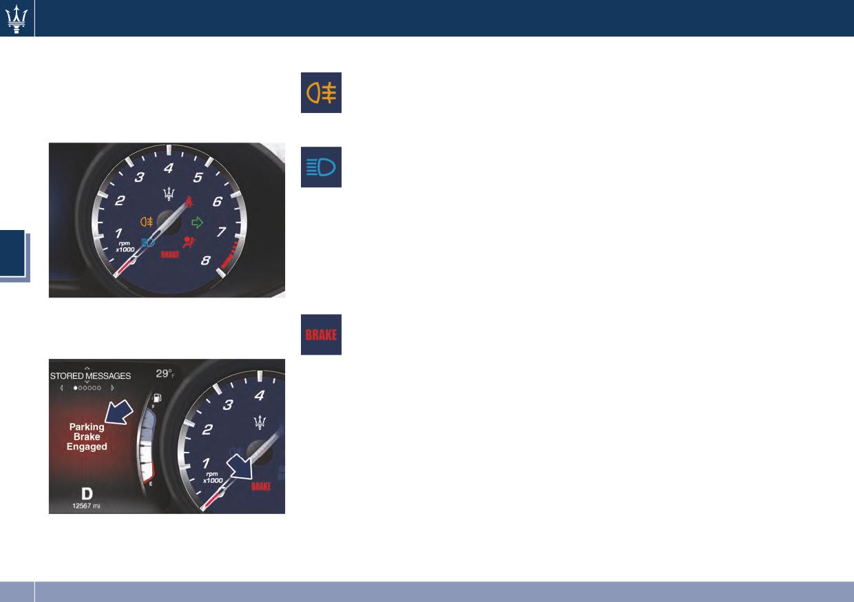
Warning Indicators on Rev Counter
Rear Fog Light Indicator
could be a brake hydraulic system
malfunction or a problem with the
Following indicator lights and linked
This indicator lights up when
brake booster detected by the ABS/ESC
messages are displayed on the Rev
the rear fog light is switched
system.
Counter on sector 1 of the display (see
on.
If this occurs, the light will remain lit
“TFT Display” in this chapter).
High Beam Indicator
until the problem has been solved.
This indicator lights up when
If the problem concerns the brake
the high beams are switched
booster, the ABS pump will run when
on or when are flashed by
engaging the brake and a brake pedal
using the multifunction lever.
pulsation may be felt during each stop
Push the left multifunction lever
of the vehicle.
forward to switch the headlights to
Inefficiency of one of the dual brake
high beam function, and pull toward
system cycle is indicated by the brake
4
yourself (back to normal position) to
warning light, which will turn on when
reset the low beams.
the brake fluid level in the master
cylinder has dropped below a certain
Brake Indicator Light
Malfunction messages will be stored in
level.
This light monitors various
“Stored Messages” (see example in
The light will remain lit until the
brake functions, including
picture).
problem has been diagnosed and
brake fluid level and parking
serviced.
brake engagement.
If a brake failure occurs, visit the
If the brake light illuminates the
Authorized Maserati Dealer as soon as
parking brake may be engaged, the
possible in order to have the brake
brake fluid level mat be low or a
system checked and serviced.
problem with the anti-lock brake
In the event of an Electronic Brake
system (ABS) reservoir may have
Force Distribution (EBD) failure, both
occurred.
the brake indicator light and the ABS
In all the above situations, a related
light illuminate.
message will be displayed.
Immediate repair of the ABS system is
If the light still illuminates when the
required.
parking brake has been disengaged,
Functioning of the brake warning light
and the fluid level is at the full mark
can be checked by turning the ignition
on the master cylinder reservoir, there
switch from OFF to RUN position.
140
Dashboard Instruments and Controls
The light should illuminate for
RUN. If the light does not illuminate
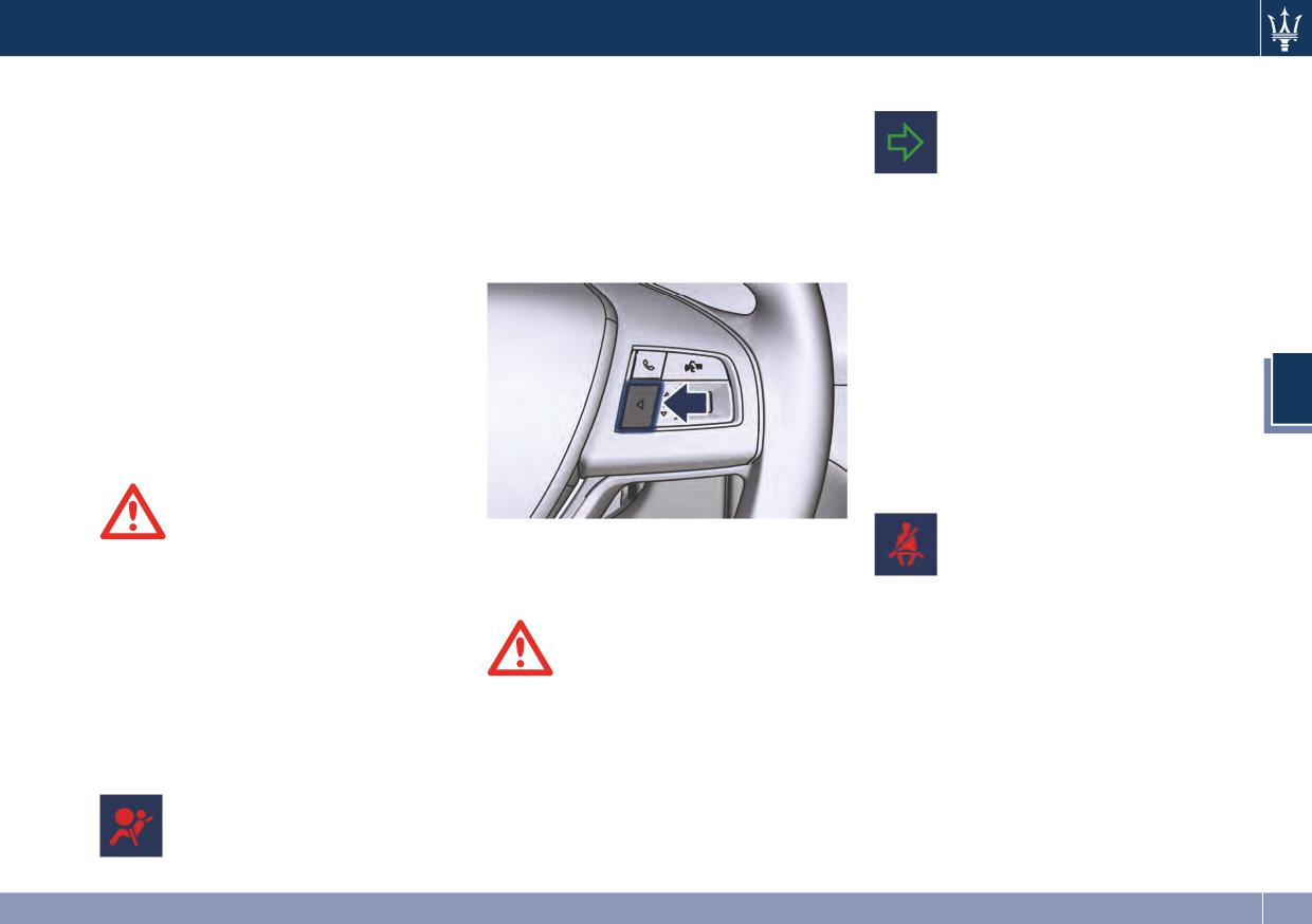
Right Turn Signal Indicator
approximately 2 seconds.
while starting the engine, stays lit, or
This indicator lights up when
The light should switch off unless the
switches on while driving, have the
the right turn signals or the
parking brake is engaged or a brake
system checked at an Authorized
hazard flashers are switched
fault is detected. If the light does not
Maserati Dealer as soon as possible.
on.
illuminate, have the warning light
In the latter case, the message will
The indicator will flash at the same
checked by an Authorized Maserati
remain displayed: to hide it, press ◄
frequency of the turn signals and is
Dealer.
on the steering wheel right side.
controlled by the turn signal lever.
The light will also switch on when the
If the vehicle electronics sense that the
parking brake is engaged with the
vehicle drives for more than 1 mile
ignition switch in RUN position.
(1.6 km) with either turn signal on, a
This light only indicates the brake is
continuous sound will advise the
engaged but not the clamping force
driver to turn the signal off.
4
of the parking brake to the wheels. To
If the indicator flashes at a fast rate,
fully engage the parking brake, please
check for a defective outside indicator
refer to “Parking Brake” in section 5.
light bulb.
Seat Belt Reminder Light
When the ignition switch is in
WARNING!
See “Supplemental Restraint System
RUN, the seat belt reminder
Driving a vehicle with the red brake
(SRS) - Air bags” in section 2 for
light will light up for a few
light on could be very dangerous and
further information.
seconds as a bulb check.
is not recommended. Part of the brake
During the bulb check, you will hear
system may have failed, resulting in
an acoustic signal if one or both front
increased braking distances and the
WARNING!
seat belts are unbuckled.
risk of an accident. Have the vehicle
If the warning light remains ON or if it
After the bulb check or while driving,
checked as soon as possible at an
does not illuminate or illuminates
if a seat belt remains unbuckled, the
Authorized Maserati Dealer.
while driving, contact your
seat belt reminder light will illuminate
Authorized Maserati Dealer as soon as
in addition to the acoustic signal and a
Air Bag Indicator Light
possible.
message will indicate which belt is
This light will illuminate for a
unbuckled.
few seconds for a bulb check
when the ignition switch is in
141
Dashboard Instruments and Controls
TFT Display
4
Position within the submenus and
scroll arrows (example: 1 of 5).
WARNING!
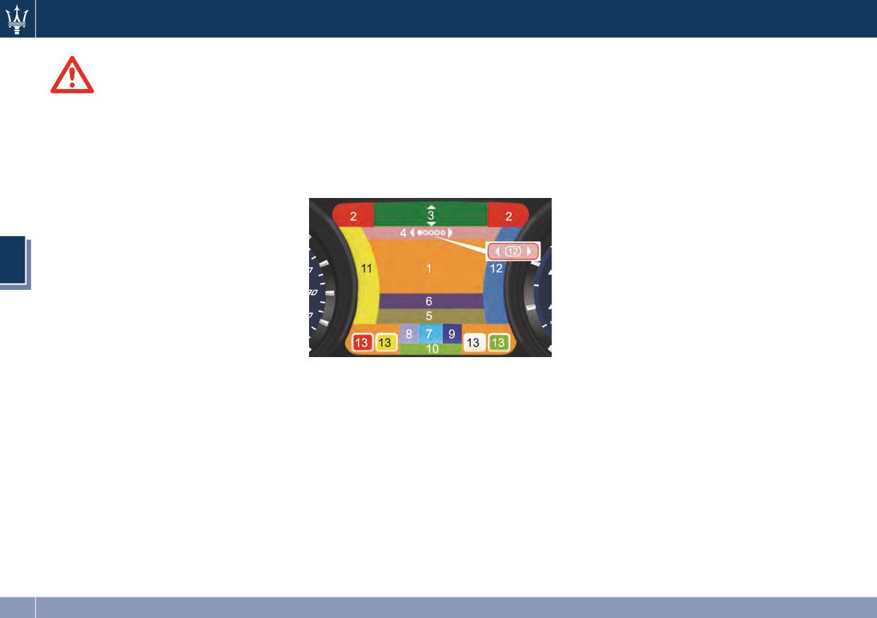
When operating, the TFT Display is
There can be maximum 9
divided into sectors including menus
Maserati urges you to use the seat
displayable submenu positions.
and sub-menus, running data, warning
belts correctly fastened and adjusted
When the number of submenu
lights and messages.
at all times. Correct use of the seat
points exceeds 9, the points are
The different sectors of the display
belts can help reduce the risk of
replaced by a numerical value
layout are shown in the following
serious injury in the event of an
within the scroll arrows (in the
picture.
accident. Do not pass seat belts over
example: 12).
sharp edges. They could tear. Do not
5
Submenu Titles.
pin anything to the seat belts. This
6
Menu Instruction.
could reduce their initial strength and
cause them to tear in the event of a
7
(P, R, N, D, M) shift position
4
crash.
indicator.
8
Sport or Normal driving mode.
Refer to “Occupant Restraint Systems”
in section 2 for further information.
9
Gear engaged.
10
Complete Odometer.
11
Engine Temperature Gauge.
12
Fuel Gauge.
1
Main area.
13
Distinctive Quadrants for
2
User-selectable information
indicators according to priority
(data, time, temperature,
and function (see “Indicators on
compass, etc.).
Display” in this chapter).
3
Main menu titles with scroll
arrows.
142
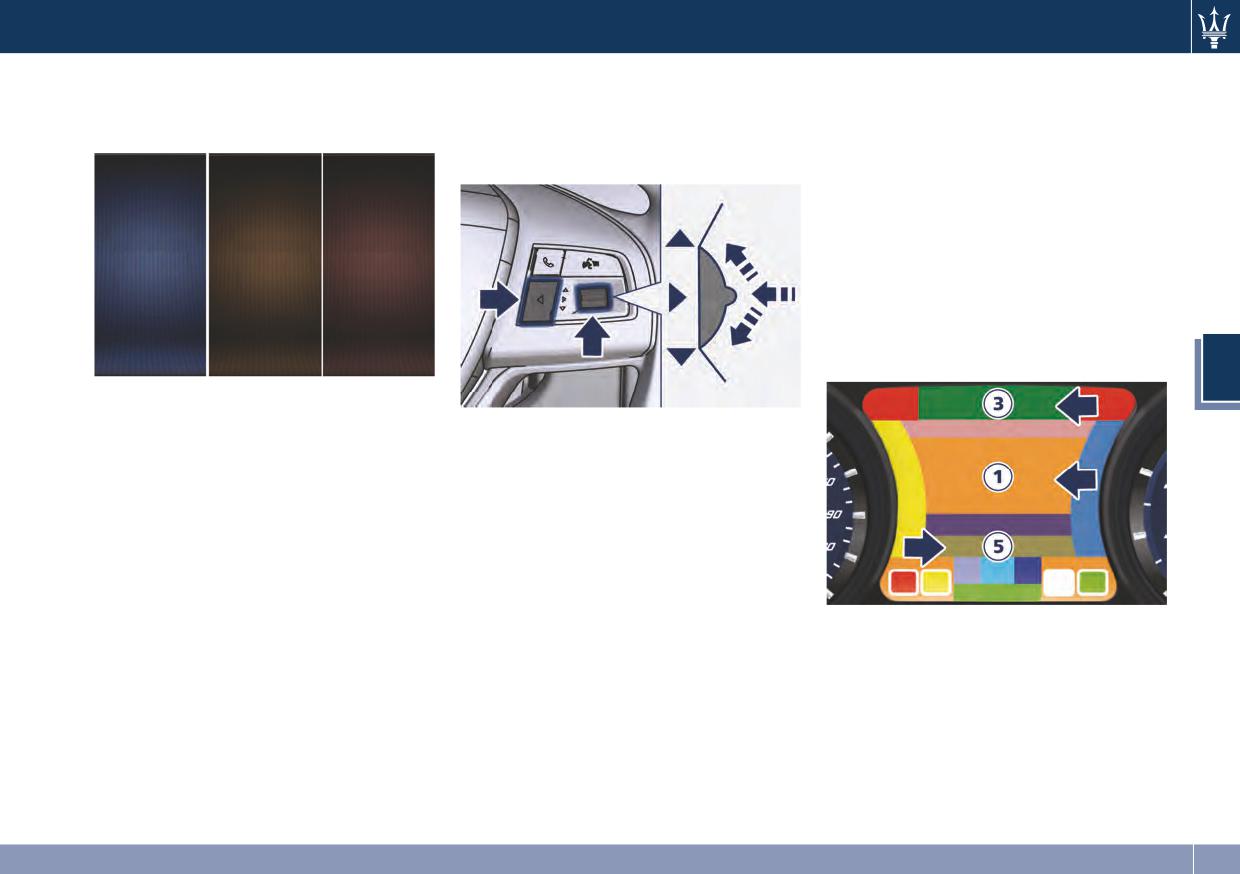
Dashboard Instruments and Controls
The display background may change
Main- and Submenu
Press and release the switch (►) to
according to the type of message
enter the information screens or a
Operate the controls on the right side
displayed.
submenu. Keep the switch (►) pressed
of the steering wheel to scroll, modify
for 2 seconds to restore the
and program the Main- and Submenu.
selected/displayed functions.
The sub-menu title selected will be
displayed in sector 5 (Submenu Title).
Within a submenu, press and release
the ▲ and ▼arrow buttons to scroll
through the menu.
Press the ◄ button to return to the
main menu from an item of interest or
from an information screen.
4
• Blue color: normal conditions.
• Yellow color: low-critical warning.
Press and release the multifunction
• Red color: high-critical warning.
switch in the ▲ and ▼ arrow
directions to scroll upwards and
downwards the main menu titles.
The main screen area in sector 1
(Menu Area) will be updated and the
selected title will be shown in sector 3
(Main Menu Title).
143
Dashboard Instruments and Controls
Main Menu & Submenu Content Overview
Pos.
Main menu
Submenus
From mph
DIGITAL SPEED -
1.
to km/h or vice
SPEEDOMETER
versa
AWD Torque
Individual Tire
Transmission
2.
VEHICLE INFO
Oil Temperature
Oil Pressure
Distribution (V6
Pressure Monitor
Temperature
Engine only)
Current, Range,
3.
FUEL ECONOMY
Average
Distance,
4
Average, Avg.
4.
TRIP A
speed, Elapsed
Time
Distance,
Average, Avg.
5.
TRIP B
speed, Elapsed
Time
Current media
6.
AUDIO
Source and track
STORED
Example: Coolant
7.
MESSAGES
Low
Cluster upper left
Cluster upper
8.
SCREEN SETUP
Restore Defaults
information
right information
VEHICLE
Electric Parking
Set Speed
9.
SETTINGS
Brake Disable
Warning
144
Dashboard Instruments and Controls
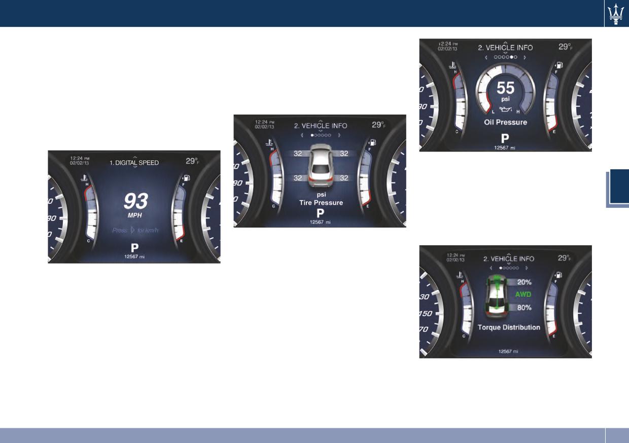
1. DIGITAL SPEED - SPEEDOMETER
• Individual tire pressure monitor
Press and release the central switch in
Indicates the pressure of each
the ▲ or ▼ arrow directions until
individual tire (see example below).
"Digital Speed" is displayed.
Please refer to “Tire Pressure
Pressing and releasing the switch (►)
Monitoring System (TPMS)” in
will toggle the unit of measure
section 5 for further information.
between mph or km/h.
Press and release the ◄ button to
return to the main menu.
• AWD Torque Distribution (V6
Engine)
Display a vehicle icon with torque
4
distribution in front and rear axle
and “AWD” if all wheel drive is
active. Displays “RWD” if all wheel
drive is inactive.
• Transmission temperature
Displays the current transmission
temperature.
2. VEHICLE INFO
• Oil Temperature
Press and release the switch in the ▲
Displays the current engine oil
or ▼ arrow directions until "Vehicle
temperature.
Info" is displayed.
• Oil Pressure
Press and release the switch (►) to
Displays the current engine oil
access the submenu.
pressure (see example).
Press and release the switch in the ▲
or ▼ arrow directions to scroll
through the following information
V6 Engine
displays and in the (►) arrow direction
Press and release the ◄ button to
to visualize the selected information.
return to the main menu.
145
Dashboard Instruments and Controls
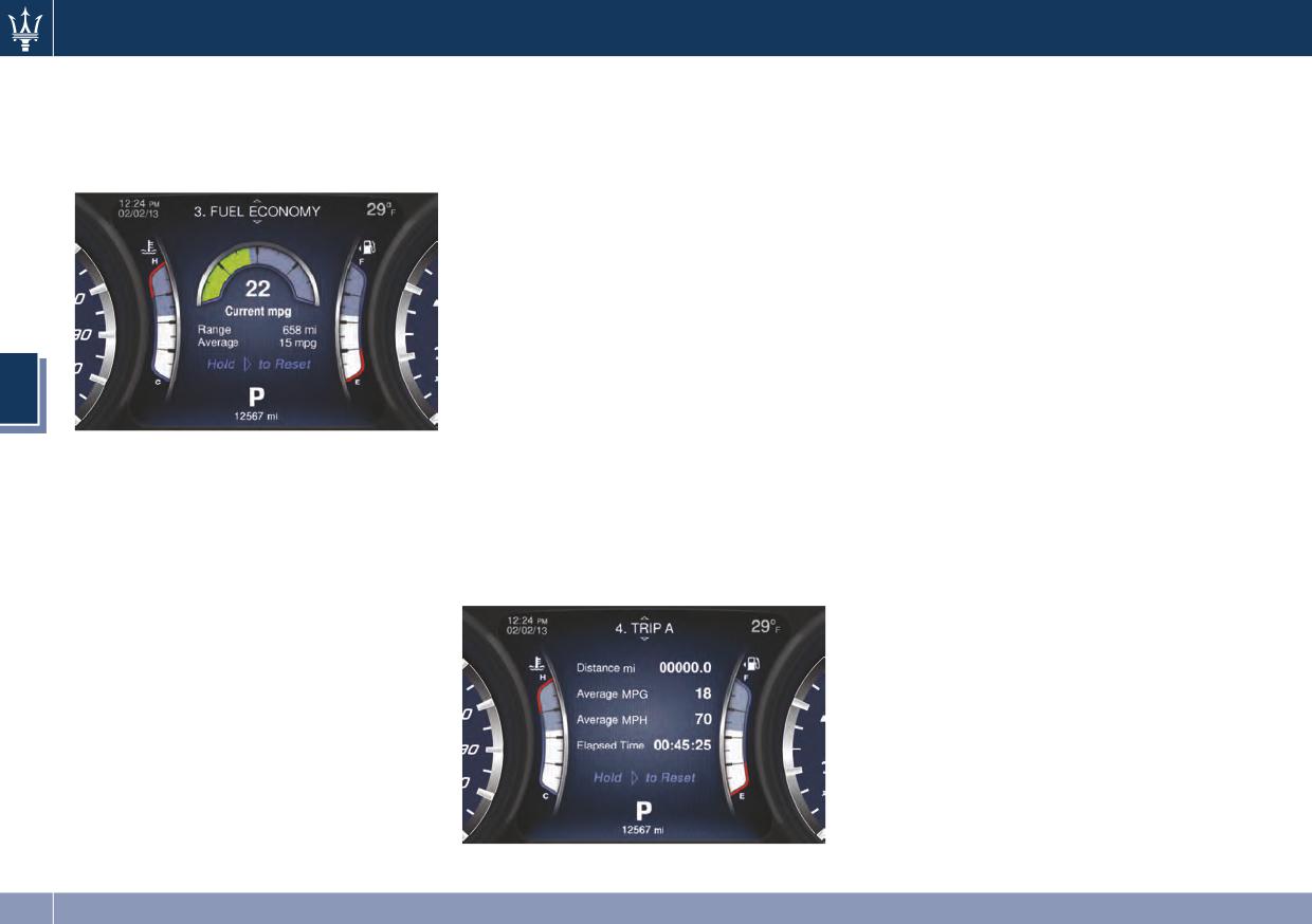
3. FUEL ECONOMY
• Fuel economy average in mpg or
The screen will display the following:
l/100km
Press and release the switch in the ▲
• Distance traveled in miles or km
or ▼ arrow directions until "Fuel
Shows the average fuel economy
Shows the total covered distance
Economy" is displayed.
since the last reset.
since the last reset.
Press the central switch (►) for 1
• Average consumption in mpg or
second and release to reset the Fuel
l/100km
Economy “Average”.
Shows the average fuel
When the fuel economy is reset, the
consumption since the last reset.
display will read “Reset” or show
• Average speed in mph or km/h
dashes for two seconds.
Shows the average speed since the
Then, the history information will be
last reset.
erased, and the averaging will
4
• Elapsed Time
continue from the last fuel average
reading before the reset.
Shows the total time of travel since
Press and release the ◄ button to
the last reset in
The screen will display the following:
return to the main menu.
“hours:minutes:seconds” Elapsed
• Current fuel economy in mpg or
Time will increment when the
4. TRIP A - 5. TRIP B
l/100km
ignition switch is in the RUN or
Shows the instantaneous fuel
Press and release the switch in the ▲
START position.
economy.
or ▼ arrow directions until "Trip A" or
Press the central switch (►) for 1
“Trip B” is displayed.
• Range in miles or km
second and release to reset Trip A or
Shows the range since the last fuel
Trip B.
average reset.
Press and release the ◄ button to
return to the main menu.
When the fuel economy is reset, the
display will read “Reset” or show
dashes for two seconds.
Then, the history information will be
erased, and the averaging will
continue from the last fuel average
reading before the reset.
146
Dashboard Instruments and Controls
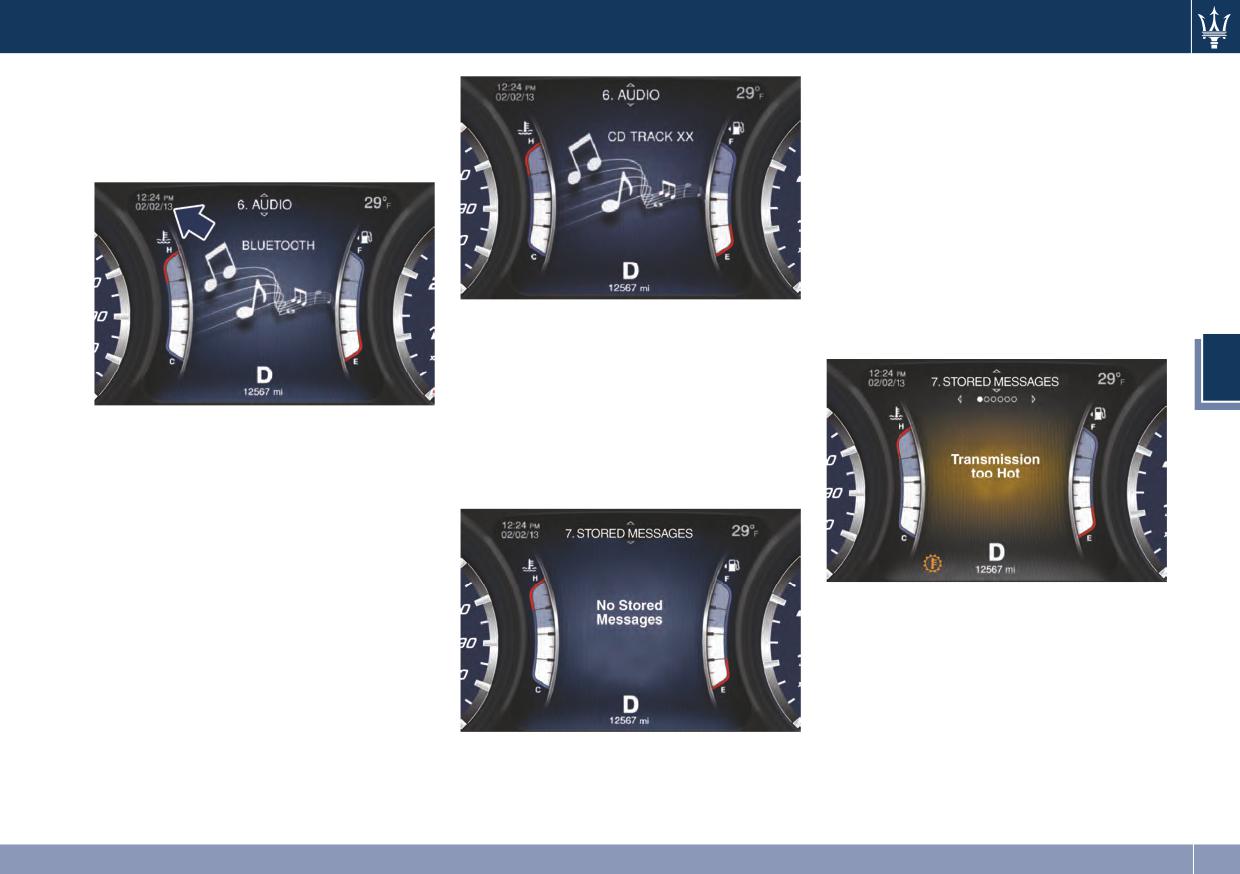
6. AUDIO
Press and release the switch in the ▲
or ▼ arrow directions to scroll the
Press and release the switch in the ▲
stored messages.
or ▼ arrow directions until “Audio” is
When the number of messages
displayed.
exceeds 9, the submenu points will be
replaced by a numerical value
indicating the message number. Press
and release the switch (►) to view the
selected message (for example
“Transmission too Hot”). Press and
release the ◄ button to return to the
7. STORED MESSAGES
main menu.
Press and release the central switch in
the ▲ or ▼ arrow directions until
4
“Stored Messages” is displayed.
The system will either display the
The display will show the audio status
number of the stored messages (if any
(source and information) as set on the
available) or “No Stored Messages” as
MTC. It is possible to display up to 13
shown in picture.
alphanumeric characters. Displays
Audio Status are:
• AM: Frequency;
• FM: Frequency, Station provided
info;
• CD: Track info;
• UCI/BTSA with metadata: Artist,
Song, Album.
Press and release the ◄ button to
return to the main menu.
147
Dashboard Instruments and Controls
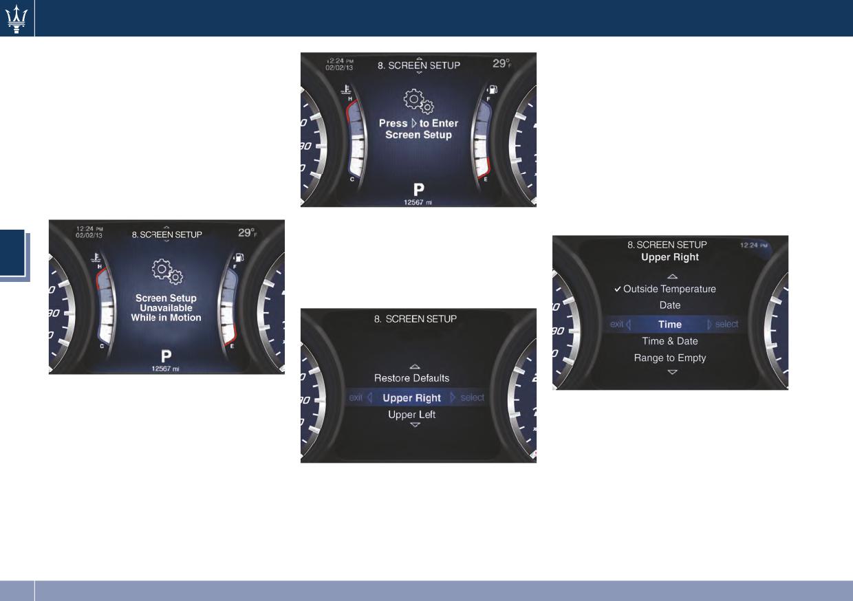
8. SCREEN SETUP
• OK.
Press and release the switch in the ▲
• Cancel.
or ▼ arrow directions until “Screen
For the “Upper Right” and “Upper
Setup” is displayed.
Left” titles there are following
Press and release the switch (►) to
options:
access the submenu.
• None.
If the vehicle exceeds 5 mph (8 km/h),
• Compass.
this feature is locked out and the main
• Outside Temperature.
screen shows “Screen Setup
Unavailable While in Motion”.
• Date.
Scroll the positions on the menu with
• Time (see picture).
the switch in the ▲ or ▼ arrow
4
directions:
• Restore Defaults.
• Upper Right (see picture).
Operate this function with the vehicle
stopped and transmission in P (Park)
• Time & Date.
position.
• Range to Empty.
In order to enter a function, press the
• Average fuel consumption MPG (or
switch (►) as shown in the picture.
L/100km).
• Upper Left.
• Current fuel consumption MPG (or
Press and release the central switch
L/100km).
(►) to view the options related to the
• Trip A Distance.
menu title selected.
• Trip B Distance.
For the “Restore Defaults” title there
are following options:
148
Dashboard Instruments and Controls
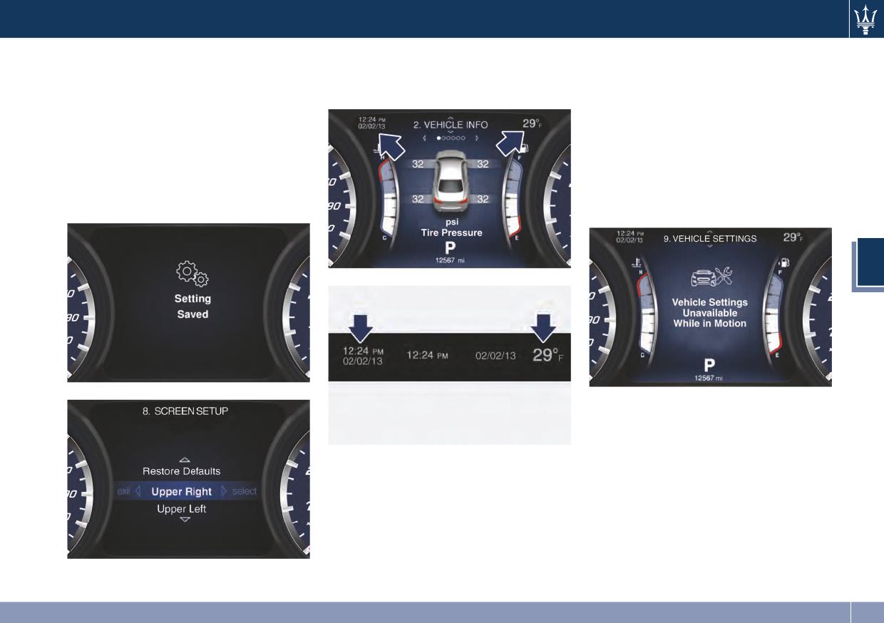
Scroll with the switch in the ▲ or ▼
The images show the default items,
9. VEHICLE SETTINGS
arrow directions to view the selectable
which are also displayed on the upper
Press and release the switch in the ▲
item. A check mark will remain next to
part of the MTC.
or ▼ arrow directions until “Vehicle
the previously selected item until a
Settings” is displayed.
new selection is made.
Press and release the switch (►) to
Press and release the switch (►) to
access the submenu.
select an item. “Setting Saved”
If the vehicle exceeds 5 mph (8 km/h),
notification appears as a popup for 2
this feature is locked out and the main
seconds, then the display will show
screen shows “Vehicle Settings
the last modified item.
Unavailable While in Motion”.
4
Operate this function with the vehicle
stopped and transmission in P (Park)
position.
In order to enter a function, press the
Press and release the ◄ button to
switch (►) as shown in the picture.
return to the main menu.
149
Dashboard Instruments and Controls
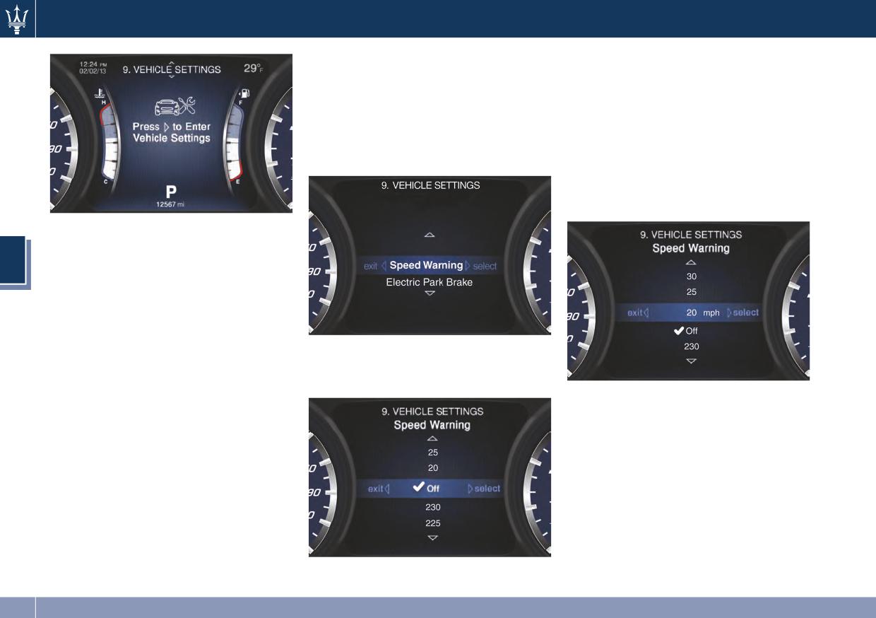
Example: How to modify the Speed
Scroll with the switch in the ▲ or ▼
Warning Status
arrow directions to view the selectable
Scroll with the switch in the ▲ or ▼
options.
arrow directions to view the selectable
Speed values are in loop, keeping the
items.
switch pressed in the ▲ or ▼ arrow
Press and release the switch (►) to
directions will increase scroll speed.
select “Speed Warning”.
Press and release the switch (►) to
select the option. A check mark will
remain next to the previously selected
item until a new selection is made.
Scroll with the switch in the ▲ or ▼
arrow directions to view the selectable
4
items:
• Electric Park Brake.
• Speed Warning.
NOTE:
In order to modify the “Electric Park
Press and release the switch (►) once
Brake” function, please see chapter
again to view the related options:
“Parking Brake” in section 5.
“Off” is the default status.
The “Setting Saved” notification
appears as a popup for 2 seconds, then
the display will show the last modified
item.
150
Dashboard Instruments and Controls
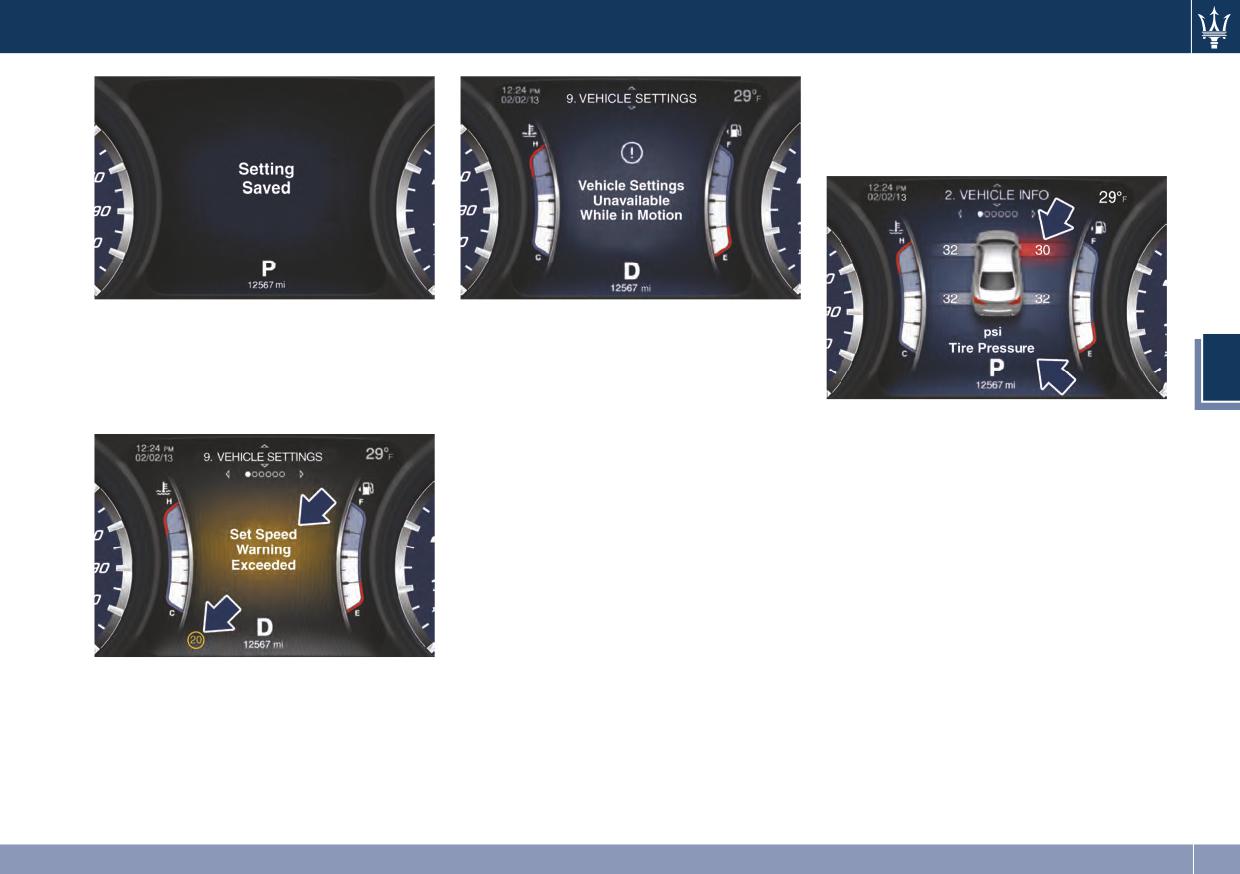
Examples of this message type are
"Right Front Turn Signal Light Out"
and "Tire Pressure” low (as shown
in the picture).
When the set speed is exceeded, the
Messages on Main Display Area
driver is alerted by an acoustic signal,
The main display area also displays
a telltale indicating the speed limit,
"pop up" messages. These pop up
4
and a pop-up message indicating that
messages fall into several categories:
the limit has been exceeded.
• Unstored Messages
• Five-Second Stored Messages
This message type is displayed until
When the appropriate conditions
the condition that activated the
occur, this type of message appears
message is cleared.
on the main display area for five
seconds and then returns to the
Examples of this message type are
previous screen. Most of the
"Turn Signal On" (if a turn signal is
messages of this type are then
left on) and "Lights On" (if the
stored (as long as the condition that
driver leaves the vehicle).
activated it remains active) and can
be reviewed from the "Stored
Messages" main menu item. As long
The pop-up message and the telltale
as there is a stored message, an "i"
will be displayed for 5 seconds before
will be displayed in the
returning to the previous menu.
compass/outside temp sector.
151
Dashboard Instruments and Controls
• Unstored Messages with Ignition
• Five-Second-displayed Navigation
Warning Lights on Display
Switch in RUN
Messages
NOTE:
This message type is displayed until
When the navigation menu is
• In sector 13 of the display more
the ignition switch is in RUN
enabled on the MTC, information
telltales are displayed while
position. An example of this
pop ups will be displayed for 5
dedicated messages are shown on
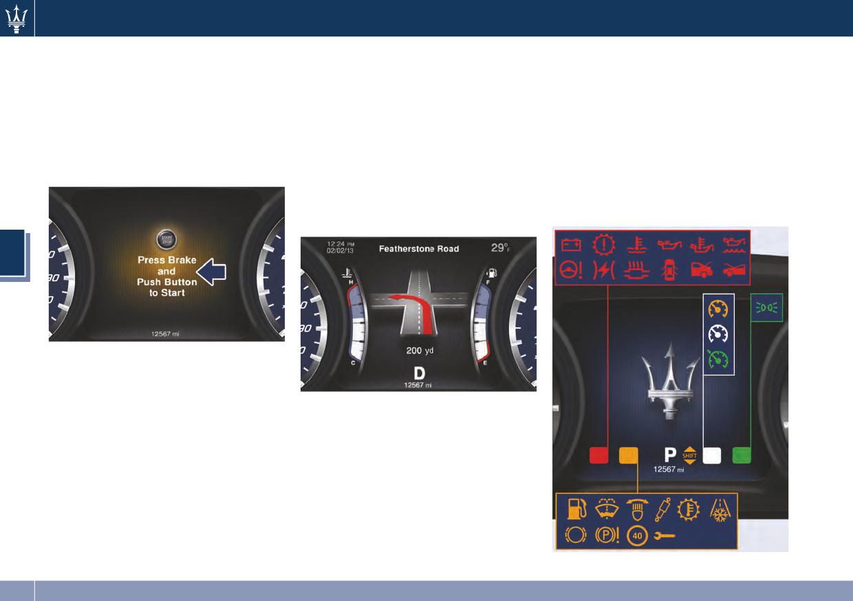
message type is "Press Brake and
seconds while changing direction or
sector 1 for 5 seconds, unless
Push Button to Start" (as shown in
approaching a turning point.
otherwise indicated.
the picture).
On highway, the first pop up will be
• Malfunction messages will be saved
displayed at 2 miles (3.2 km) from
in “Stored Messages”.
the turn, on roadway, at 1 mile
(1.6 km).
4
• Five-Second Unstored Messages
When appropriate conditions occur,
this type of message appears on the
main display area for five seconds
While approaching the turn, further
then returns to the previous screen.
pop ups will be displayed starting at
Examples of this message type are
430 yd (400 m) from the turning
"Memory System Unavailable
point and the countdown to 0 miles
Vehicle Not in Park" and "Automatic
(meters).
High Beams Enabled".
152
Dashboard Instruments and Controls
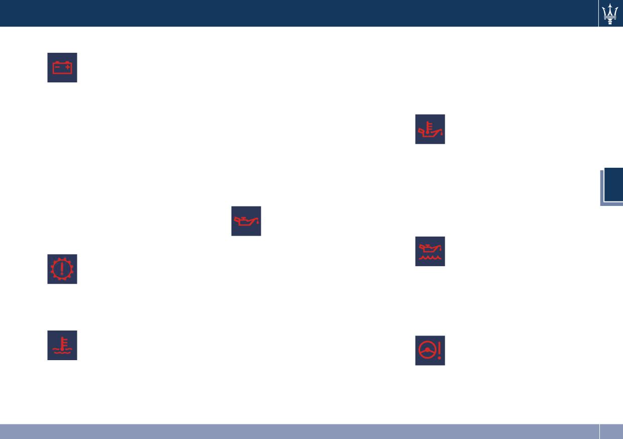
Charging System Warning Light
message, and triggering and acoustic
under the engine hood (see
signal by reaching the set threshold.
“Maintenance Procedures” in section
This telltale shows the status
If the warning light switches on while
7).
of the electrical charging
driving, safely pull over and stop the
If the problem persists, contact an
system. If the telltale stays on
vehicle. If the A/C system is on, turn it
Authorized Maserati Dealer.
or comes on while driving,
off. Also, shift the transmission into N
turn off some of the vehicle's
Engine Oil Temperature Indicator
(Neutral) and idle the vehicle. If the
non-essential electrical devices or
This light indicates that the
temperature does not return to
increase engine speed (if at idle). If
engine oil is overheated. The
normal, immediately turn the engine
the charging system telltale remains
indicator is combined with the
off and contact an Authorized
on, it means that the vehicle is
related displayed message. In
Maserati Dealer.
experiencing a problem with the
this case, drive carefully until the
Check “Engine Overheating” in
charging system. IMMEDIATELY
temperature drops back to normal
section 6 for more information.
contact an Authorized Maserati
level and the indicator light turns off.
4
Dealer to have the vehicle serviced.
Low Oil Pressure Indicator
If the problem persists, contact an
If jump starting is required, refer to
Under normal conditions, the
Authorized Maserati Dealer.
“Jump Start Procedures” in section 6.
warning light illuminates
Low Engine Oil Level Indicator
Automatic Transmission Failure
when the ignition switch is
This indicator and the related
Indicator
turned to RUN and goes off as
displayed message, indicate a
This indicator and related
soon as the engine is started.
low engine oil level.
displayed message, indicate
If the warning light stays or turns on
The engine oil level must be
transmission failure. If the
while driving, the engine oil pressure
checked with the dipstick fitted under
failure permits, slowly drive to
is too low. The warning light is
the engine lid (see “Maintenance
the nearest Maserati Service Center.
combined with a displayed message
Procedures” in section 7).
and an acoustic signal that will last 4
Engine Temperature Warning Light
minutes. In this case, turn the engine
Power Steering Failure Warning Light
This warning light notifies
off immediately and carry out the
This warning light, and the
when the engine is
necessary checks.
related message, illuminate
overheated. As temperature
Do not operate the vehicle until the
when the Electric Power
rises and the gage displayed in
problem has been checked and
Steering is not operating and
sector 11 approaches “H”, this
serviced. This light does not indicate
needs service.
warning light will illuminate
the oil level. The engine oil level must
If the problem persists, contact an
combined with the related displayed
be checked with the dipstick located
Authorized Maserati Dealer.
153
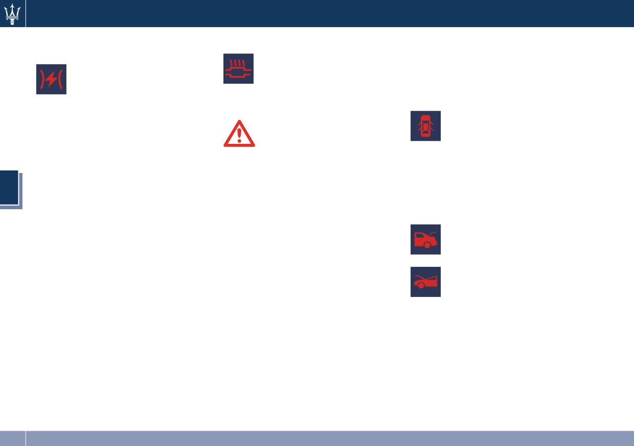
Dashboard Instruments and Controls
Electronic Throttle Control (ETC)
Catalyst Over Temperature Indicator
• Maserati is not responsible for
Indicator
damage deriving from non-
This warning light, and the
This light combined to the
related message, light up if
compliance with the above
related message displayed on
the engine runs irregularly
mentioned warnings.
sector 1 for 5 seconds,
with consequent high
Door Ajar Indicator
indicates a failure of the
temperature in the exhaust system.
Electronic Throttle Control (ETC)
This indicator illuminates
system. If the indicator turns on while
when one or more doors are
driving, have the system checked by
ajar. The indicator will show
WARNING!
the Authorized Maserati Dealer.
which door is ajar. When one
• If the warning light is accompanied
When detecting a failure, the light
or more doors are open, a related
by the message “Catalyst Temp
indicator will illuminate while the
message will be displayed if the vehicle
Getting Hot Reduce Speed”: the
engine is running. Cycle the ignition
is running at speed 5 mph (8 km/h) or
4
temperature of the catalytic
switch when the vehicle has
faster.
converters is too high. The driver
completely stopped and the shift lever
must slow down immediately until
Trunk and Engine Lid Ajar Indicators
is placed in P (Park) position: the light
the warning light turns off.
These light indicators will
indicator should turn off.
• If the message “Catalyst Temp Hot
illuminate to indicate that the
If the indicator remains lit with the
Stop Safely Wait To Cool” appears
trunk or engine lid is ajar.
engine running, you can still drive your
after decelerating: the temperature
When the trunk or engine
vehicle. However, contact the
in the catalytic converters has
compartment is open, a
Authorized Maserati Dealer as soon as
reached an abnormal level and the
related message will be
possible.
catalytic converters could be
displayed with the warning
If the indicator is flashing while the
damaged. Drive slowly to the
indicator if the vehicle is running at
engine is running, immediate service is
nearest workshop.
speed 5 mph (8 km/h) or faster.
required. You may experience reduced
performance, an elevated/rough idle
• If the light turns on permanently 3
or engine stall and your vehicle may
times the engine will stop. It will be
require towing.
possible to restart the vehicle only
after a key-off / key-on cycle. Then
slowly drive to the nearest Maserati
Service Center.
154
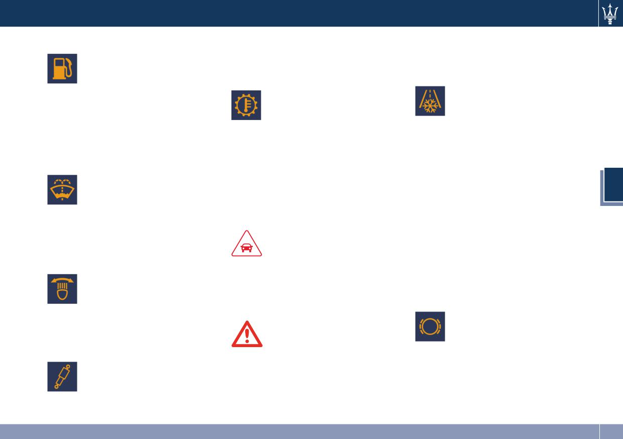
Dashboard Instruments and Controls
Low Fuel Indicator
Please contact an Authorized Maserati
with hot engine or exhaust
Dealer to check the system.
components and cause a fire.
When the fuel level reaches
approximately 4.2 Gallons
Transmission Temperature Warning
Ice Hazard Warning Light
(16.0 L) this light will turn on,
Light
and remain on until fuel is
When the external
This warning light and the
added; the related message will also
temperature falls below 37°F
related message indicate that
be displayed.
(3°C), the temperature value
the transmission fluid
Refer to “Refueling” in section 5 for
blinks for a few seconds, the
temperature is rising.
fuel filling.
warning light turns on, a message is
If this warning light turns on, safely
displayed and an acoustic signal is
Windshield and Headlights Washer
pull over and stop the vehicle.
triggered to warn the driver of the
Low Fluid Indicator
Then, shift the transmission into P
risk of icy roadbed.
(Park) and run the engine at idle or
This indicator will illuminate
Under such conditions, we recommend
faster until the temperature drops and
4
for 5 seconds to indicate a low
to use the I C E drive mode (see
the light switches off. If the problem
level of the windshield and
“Automatic Transmission” in section 5)
persists, contact an Authorized
headlamp washer fluid. A
drive carefully and slow down as the
Maserati Dealer.
related message will be displayed.
grip of the tires may be significantly
See “Maintenance Procedures” in
reduced.
section 7 for fluid filling.
CAUTION!
The warning light flashes for 5
Adaptive Light Control System Failure
Continuous driving with the
seconds and switches off when the
transmission temperature warning
temperature reaches 43°F (6°C) or
This indicator, and the related
light illuminated will eventually cause
higher.
message, indicate a failure of
the automatic headlight
severe transmission damage or failure.
Brake Pads Wear Warning Light
aiming system.
This warning light and the
Please contact an Authorized Maserati
related message indicate that
Dealer to check the system.
the brake pads have reached
WARNING!
Suspension Failure Indicator
their wear limit.
If the transmission temperature
Please contact an Authorized Maserati
This indicator light and the
warning light is illuminated and you
Dealer to have them replaced.
related message turn on
continue operating the vehicle, in
during driving if there is a
some circumstances you could cause
failure of the suspension
the fluid to boil over, come in contact
system.
155
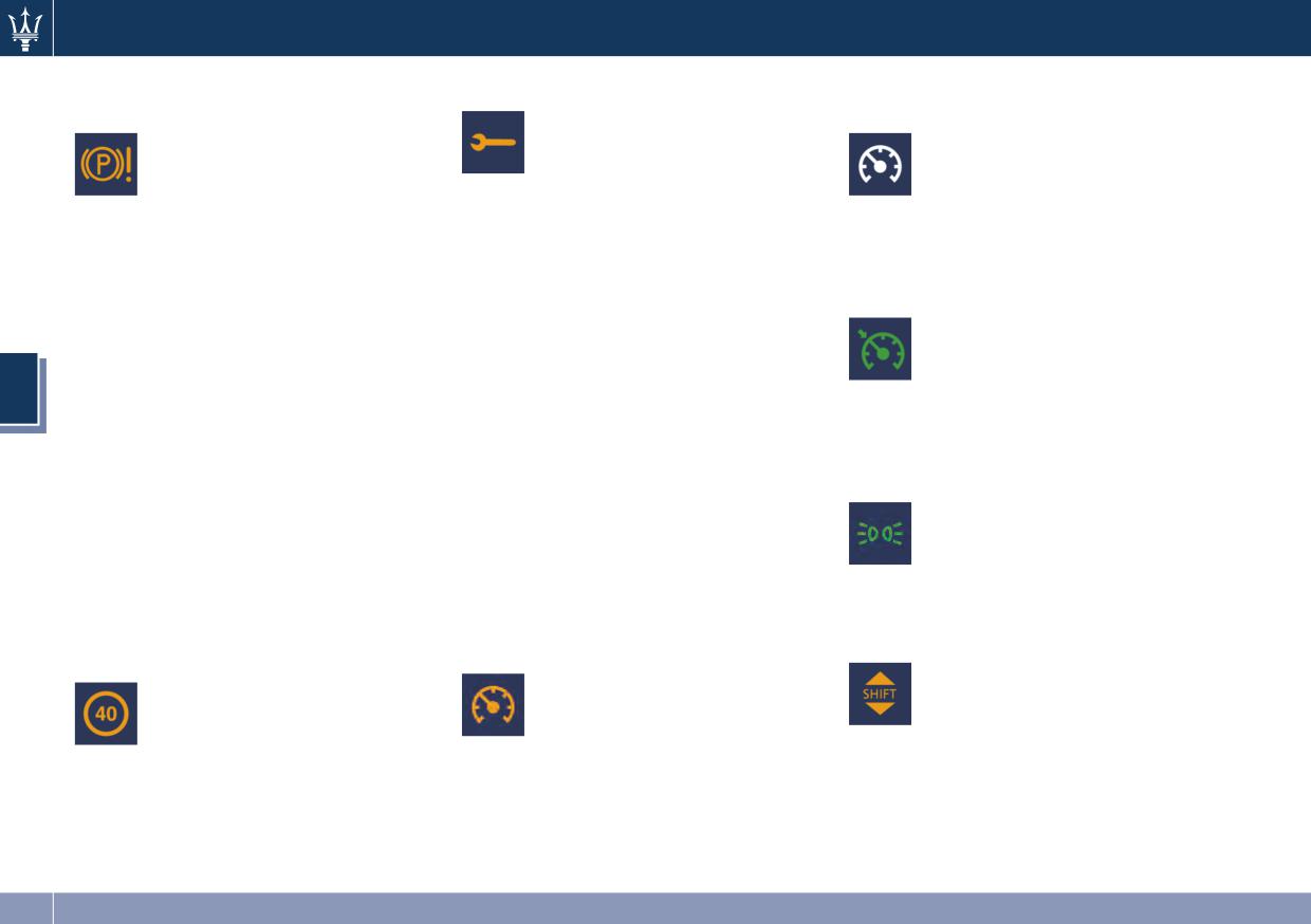
Dashboard Instruments and Controls
Electric Parking Brake Failure Warning
Oil Change Required Indicator
Electronic Cruise Control in Stand-by
Light
Indicator
The “Oil Change Required”
This warning light and related
message flashes on the display
This light indicator and related
message illuminate when
for approximately 5 seconds
message will illuminate when
there is an EPB system failure.
after an acoustic signal and it
the electronic cruise control is
The failure could also completely or
indicates that the next scheduled oil
in stand-by. For further
partially block the vehicle because the
change is due.
information, check “Electronic Cruise
parking brake could remain on even
The engine oil change indicator system
Control” in section 5.
after it has been automatically or
is duty cycle based, which means the
Electronic Cruise Control SET Indicator
manually disengaged though its
engine oil change interval may
This light indicator and related
controls. In this situation it is possible
fluctuate according to your personal
message will illuminate when
to release the parking brake by
driving style. Unless reset, this message
the electronic cruise control is
following the emergency release
will continue to display each time you
4
SET. For further information,
procedure as indicated in chapter
cycle the ignition to the RUN position.
check “Electronic Cruise Control” in
“Emergency Release of the Parking
To turn off the message temporarily,
section 5.
Brake” in Section 6.
press and release the ◄ button. To
If it is still possible to use the vehicle
reset the oil change indicator system
Park/Headlight On Indicator
(parking brake not engaged) drive to
please visit a Maserati Service Center.
This indicator will illuminate
the nearest Authorized Maserati
when the park lights or
Indicators in Sector 13 of the Display
Dealer and remember to performing
headlights are turned on.
Cruise Control, lights on and gear shift
each operation/command that the
For further information, see
indicators are displayed in sector 13 on
electric parking brake is not
“Lights” in section 3.
the right side of the total odometer.
functioning.
Gear Shift Indicator Light
Electronic Cruise Control ON Indicator
Speed Limit Exceeded Warning Light
This indicator lights up to
This light indicator and related
This warning light and related
indicate gear shift change in
message will illuminate when
message illuminate when the
order to optimize fuel
the electronic cruise control is
set speed limit is exceeded (in
consumption, see “Drive
ON. For further information,
the example shown: 40 mph
Mode” in section 5 for further
check “Electronic Cruise Control” in
or km/h).
information.
section 5.
156
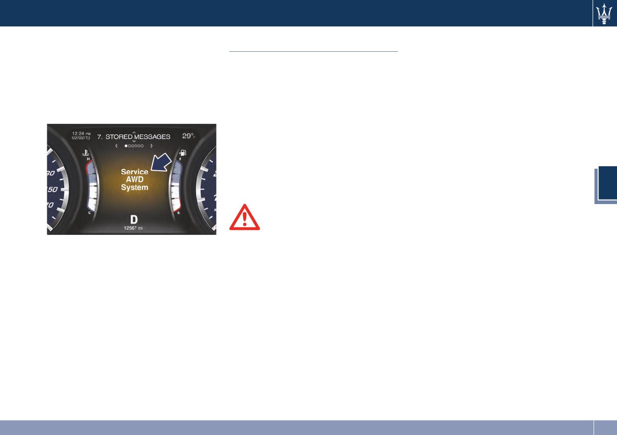
Dashboard Instruments and Controls
Service AWD System Message (V6
This vehicle is provided with a
Infotainment System
Engine)
description of the MTC System
The vehicle is equipped with the
features and listing of warnings and
The message on the TFT display will
infotainment Maserati Touch Control
precautions, which are essential for
illuminate when all wheel drive
(MTC) System, an advanced user
safe use of the system. Maserati
feature requires service. For further
interface which combines innovative
advises you to read this addendum
information, refer to “All-Wheel
and exclusive technical features
carefully and thoroughly.
Drive” in section 5.
integrating entertainment, user
settings, air conditioning, navigation,
communication and information
features within a single system.
The MTC System features an audio
system which is acoustically optimized
4
for this specific vehicle.
WARNING!
The navigation system assists the
V6 Engine
driver while driving, providing advice
and suggestions, by voice guidance
and graphic information, for the best
route to reach the set destination. The
suggestions provided by the
navigation system do not relieve the
driver from full responsibility for the
maneuvers made through traffic while
driving, or from compliance with road
regulations and other provisions
regarding road traffic. The person
driving the vehicle is always and in
any case responsible for safe driving
on the road.
157
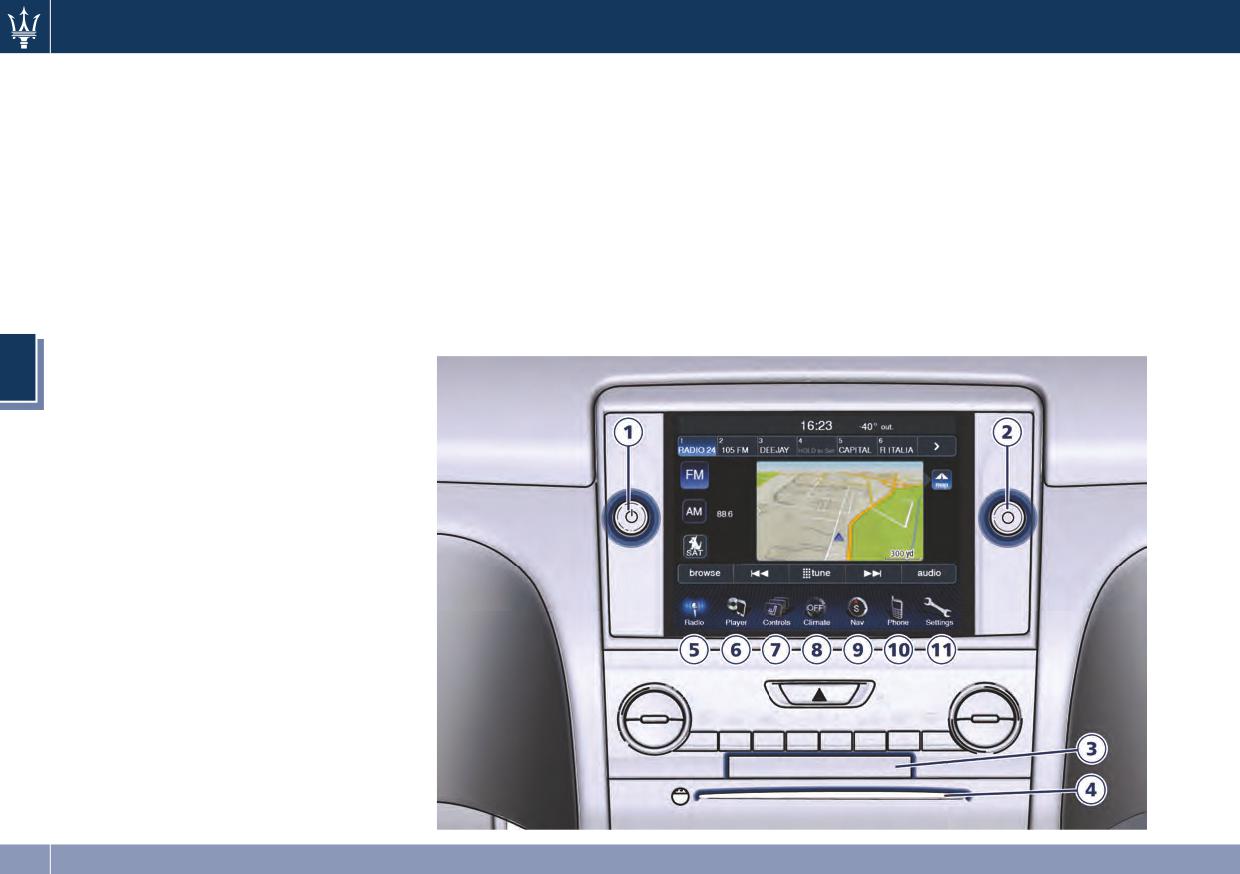
Dashboard Instruments and Controls
MTC Controls
Hard Keys
label is facing up. Press the lateral
button to eject the disc.
MTC System has a series of tools,
• SD Card slot
controls and soft-keys that are
Insert an SD Card containing any
• ON/OFF and Volume
designed to use external multimedia
navigation information, perform
Press the central button (1) to turn
resources and different audio options,
navigation functions and play media
the unit on or off. Rotate the
to change settings and to perform
files (music and images).
external regulator on the central
other functions.
button (1) to adjust the volume.
• CD/DVD slot
All controls are positioned in the
If the ignition is switched off
To be used when in Player mode.
central part of the dashboard.
(ignition switch in OFF) with the
When inserting a disc, make sure the
1
ON/OFF and Volume control.
radio in stand-by mode, the radio
2
Enter/Browse and Tune/Scroll
knob.
4
3
Card slot.
4
CD/DVD slot.
5
“Radio” soft-key.
6
“Player” soft-key.
7
“Controls” soft-key.
8
“Climate” soft-key.
9
“Nav” soft-key.
10
“Phone” soft-key.
11
“Settings” soft-key.
158
Dashboard Instruments and Controls
memorizes the stand-by mode for
• Player soft-key (6)
Audio Controls
recall at the next ignition cycle.
Press the Player soft-key to access
The vehicle is equipped with audio
Press the central button to turn the
media sources such as: Disc, USB
controls that allow both driver and
radio on.
Device and AUX as long as the
front passenger to operate the audio
It is possible to eject the CD and to
requested media is present.
system without using the touch-screen
display the time if the system is off.
• Controls soft-key (7)
keys on the MTC display. These
The navigation software is always
Press the Controls soft-key to access
controls can be used to adjust audio
working when the ignition is
the Settings list. Controls such as;
volume, change radio station or mode
switched on, even if the radio is in
Heated Seats, Heated Steering
(AM, FM, CD, etc).
standby mode.
Wheel, Ventilated Seats, etc. can be
selected or turned ON/OFF by
Steering Wheel Audio Controls
• Enter/Browse and Tune/Scroll
touching the related soft-key.
Press the central button to accept a
The sound system controls are
4
highlighted selection on the screen.
• Climate soft-key (8)
rocker-type switches with a button in
Rotate the external regulator to
the center and are located on the rear
Press the Climate soft-key to access
scroll through a list or tune a radio
side of the steering wheel, right
the air conditioning settings. See
station.
behind the front switches.
“Air Conditioning Controls” in this
The right-hand control manages
Touch-Screen Keys
section for further details.
volume and mode of the sound
The soft keys located on the lower
• Nav soft-key (9)
system.
part of the MTC display, enable
Press the Nav soft-key to access the
By pressing the top of the rocker
different function modes as briefly
Navigation feature.
switch you can increase the volume,
indicated below. For further
and by pressing the bottom of the
• Phone soft-key (10)
information refer to the dedicated
rocker switch you can lower it. Press
Press the Phone soft-key to access
booklet included in the owner
the center button to switch radio
the MTC Phone feature.
documentation.
mode (AM, FM, CD, etc.). The
• Settings soft-key (11)
• Radio soft-key (5)
left-hand control functions depend on
Press the Settings soft-key to access
the current mode set with the
Press the Radio soft-key to enter the
the list of settings.
right-hand control, and are the
Radio mode. The different tuner
following ones.
modes: AM, FM and SAT can be
selected by touching the related
soft-keys in the Radio mode.
159
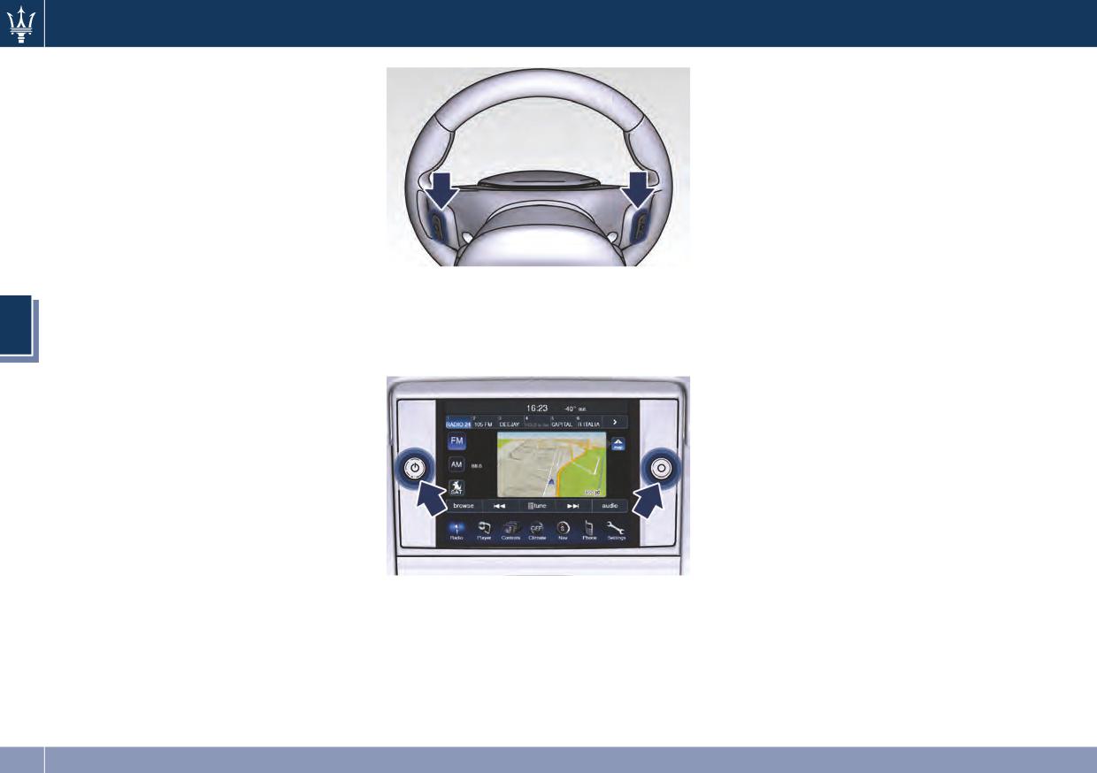
Dashboard Instruments and Controls
Radio Operation
Rotate the regulation knob clockwise
to increase volume, counter-clockwise
Pressing the top of the switch will Seek
to lower volume.
up for the next received station and
Rotate the right knob to scroll through
pressing the bottom of the switch will
the menus and change the user’s
seek down for the next received
settings (see “MTC Settings” in section
station.
4).
The button fitted in the center of the
left-hand control will tune to the next
preset station set on the MTC preset
button.
MTC Side Audio Controls
CD Player
A light press on the top of the switch
On both sides of the MTC display there
4
will play the next track on the CD.
are two rotating devices (knobs) with a
Pressing the bottom of the switch once
central button.
will go to the beginning of the current
track, or to the beginning of the
previous track if it is within one second
after the current track begins to play.
If you press the switch up or down
twice, it plays the second track; three
times, it will play the third, etc.
The center button on the left side
rocker switch has no function for a
single-disc CD player. However, if the
vehicle is equipped with a
Press the central button on the left
multiple-disc CD player, the center
side to turn the MTC on and off; rotate
button will select the next available CD
the knob to set the audio volume.
in the player.
160
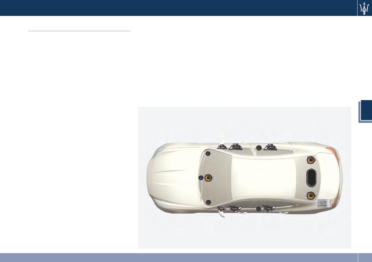
Dashboard Instruments and Controls
• 6.5 in (165 mm) CFR Woofer: 2 x 165
• 13.7 x 7.9 in (350 x 200 mm)
Audio System
mm in the front doors.
Racetrack Sub Dual VC: 1 x on the
The vehicle is equipped with an audio
rear parcel shelf.
• 6.5 in (165 mm) Black Kevlar Woofer:
system that offers superior sound
2 x 165 mm in the rear doors.
• 16-channel 1280 Watts Class-D
quality, higher sound pressure levels
• 4 in (100 mm) Yellow Kevlar
amplifier in the trunk.
and reduced energy consumption.
Midrange: 1 x center dashboard, 2 x
The system is supplied with a 12
The new system maximizes the
in the front doors, 2 x L/R surround.
channel high efficiency amplifier and
amplifier and speaker technology
is operated by a high voltage tracking
• 1 in (25 mm) MMX Tweeter: 1 x
delivering substantially higher-
power supply and drives a 7.5-channel
Center, 2 x on the dashboard L/R, 2 x
performing components and system
playback architecture. This audio
in the rear doors.
efficiency.
system offers the ability to choose
The standard sound system
"Premium" features 10 speakers and
4
can develop a sound output of 760 W.
The standard system includes:
• Four 6.5 in (165 mm) diameter
Woofers, one on each door.
• One 3.15 in (80 mm) diameter
Midrange diameter, on the top of
the dashboard.
• One 1 in (25 mm) diameter Tweeter,
2 on the upper edges of the
dashboard and 2 on rear doors.
• One 7x10 in (180x250 mm)
Subwoofer on the rear panel below
the rear window.
The vehicle can be equipped with an
"High Premium" audio system
including 15 speakers and 1280 W of
sound power, available upon request.
The optional “High Premium” sound
system includes:
161
Dashboard Instruments and Controls
Logic 7® surround sound for any audio
When in “Audio Surround” mode,
MTC Settings
source. The high-efficiency speaker
balance is set automatically. Fader
design ensures higher Sound Pressure
control is available in surround mode
The MTC System uses a combination of
Level (SPL) and exceptional dynamic
but it should be set to the center
keys able to access and change the
sound quality.
position for optimal surround
customer programmable features.
The speakers are tuned for maximum
performance.
Touch-screen keys are displayed on the
efficiency and compatible with the
lower part of the MTC display
amplifier output stage ensuring best
positioned centrally on the dashboard.
updated surround sound processing.
There is a Scroll/Enter control knob
Logic 7® multichannel surround sound
located on the right side of the MTC
technology delivers an immersive,
display.
accurate sound stage throughout the
Turn the control knob to scroll through
passenger compartment.
menus and change settings (i.e., 30, 60,
4
This surround effect is available from
90), press the button in the center of
any audio source - AM/FM/CD/Satellite
the control knob one or more times to
Radio or AUX input; and is activated
select or change a setting (i.e., ON,
through the MTC System controls. By
OFF).
selecting “Audio Surround”, you can
activate the Logic 7® multichannel
surround-sound technology in your
vehicle. All information on the current
operational mode are listed in the
specific booklet included in the on
board documentation.
The driver selectable “Video
Surround” mode (DSS) is available only
for video media sources (DVDs, Video
CDs, or other video media supported
NOTE:
by the radio). Some audio will sound
better in “DSS” modes, some other in
For further details refer to the
“Stereo” mode.
Maserati Touch Control guide.
162
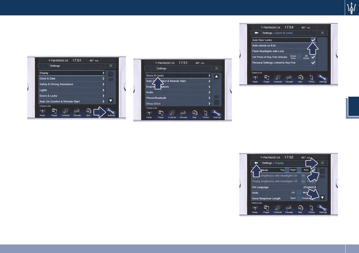
Dashboard Instruments and Controls
Customer Programmable
To make a selection, and enter the
desired function, press the
Features - MTC Settings
corresponding soft-key on the menu
Press the Settings soft-key to display
(the picture shown is “Doors and
the programmable features menu.
Locks”).
Once the procedure is completed (for
example, Display mode) press the ◄
back arrow soft-key to return to the
4
previous menu or press the upper
right X soft-key, to close the settings
In this mode the MTC System allows
screen. Pressing the ▲ or ▼ soft keys
To scroll through the functions, move
you to access following programmable
and the cursor on the right side of the
the cursor up or down, or press the
features (some of them are optional
screen will allow you to scroll up or
arrow ▼ or ▲. Once the desired mode
and may not be available on your
down through the available settings.
is entered, press and release the
vehicle): Display, Clock & Date, Safety
touch-screen area of the setting that
& Driving Assistance, Lights, Doors &
you wish to modify. The new setting
Locks, Auto-On Comfort & Remote
will be highlighted with one or more
Start, Engine Off Options, Audio,
boxes to indicate status or possible
Phone/Bluetooth and SIRIUS XM
variants of the function status. A
Setup.
check mark in a box indicates the
NOTE:
current status of the function. Press
the checkmark to cancel, or the empty
Only one touchscreen area or key may
box to insert the check mark, and
be selected at a time.
change the status of the function.
163
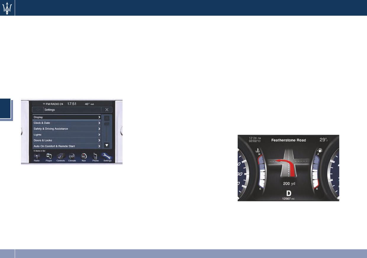
Dashboard Instruments and Controls
Display
• Display Brightness with Headlights
• Touchscreen Beep
Off
When in this display, you can turn
After pressing the Display soft-key the
following mode settings will be
When in this display, you can select
on or shut off the sound activated
available.
the brightness with the headlights
by pressure of a touch screen button
off. Adjust the brightness as
(soft-key).
• Display mode
previously explained.
• Control Screen Time-Out
When in this display you can select
• Set language
Use this mode to operate the timing
one of the auto display settings. To
change mode status, touch and
When in this display, you can select
of the control screen display.
release the Day, Night or Auto
one of available languages for all
• Navigation Turn-by-Turn Displayed
soft-key.
display descriptions, including the
on Cluster
trip functions and the navigation
By selecting this feature, the
system.
turn-by-turn directions will appear
4
• Units
on the instrument cluster along a
When in this display, you can select
programmed route until the desired
between US and Metric units of
destination is reached (see picture).
measurement in the instrument
cluster, odometer and navigation
system. The speed unit, shown in
digital format on the TFT display of
the instrument cluster, is defined
and modifiable through the controls
• Display Brightness with Headlights
located on the right side of the
On
steering wheel (see “TFT Display” in
When in this display, you can select
chapter “Instrument Cluster” of this
the brightness with the headlights
section).
on. Adjust the brightness with the +
and - setting soft-keys or by
• Voice Response Length
selecting any point on the scale
When in this display, you can change
between the + and - soft-keys.
the voice response length settings.
To change the voice response
length, touch the Brief or Detailed
soft-key.
164
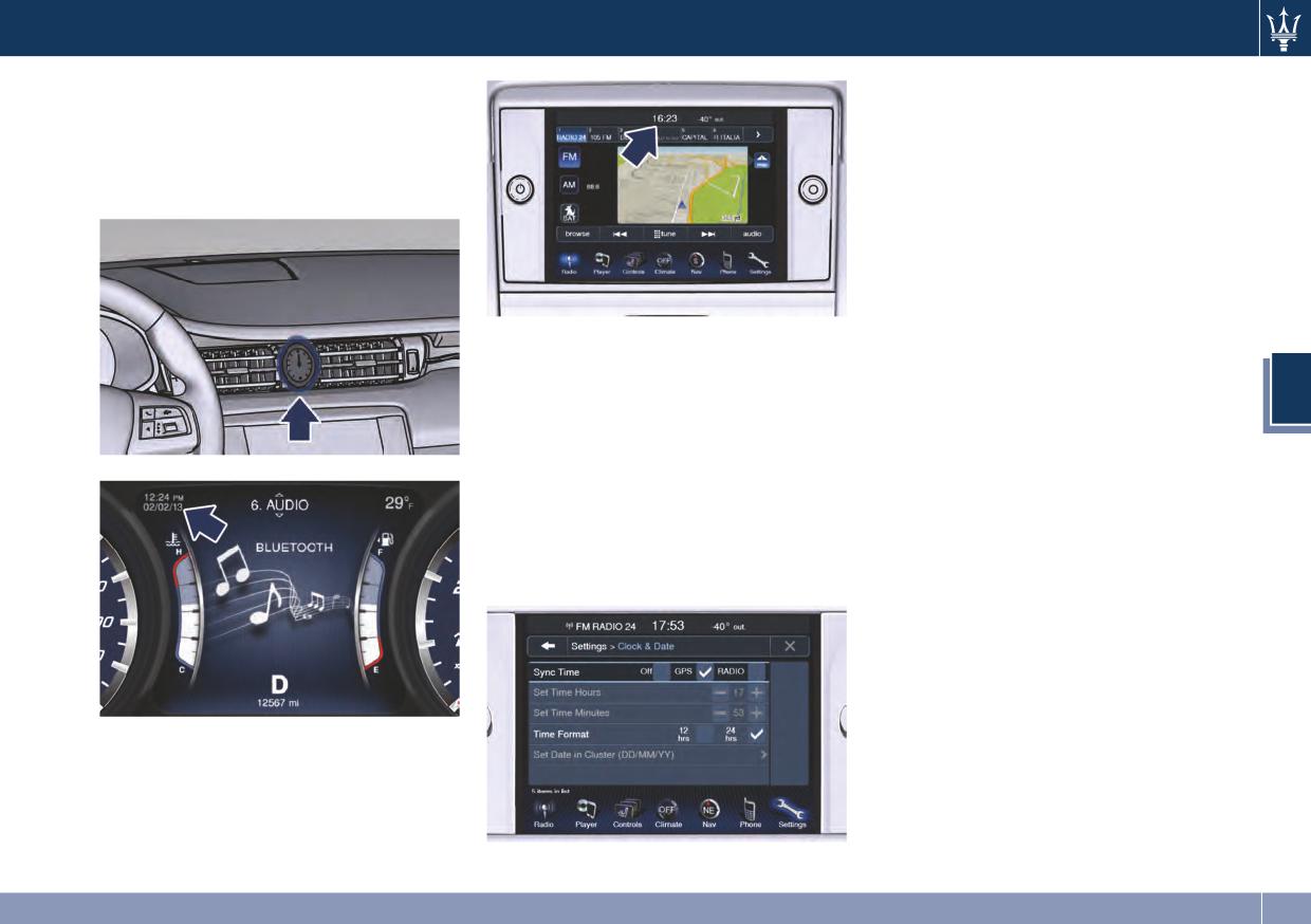
Dashboard Instruments and Controls
Clock & Date
• Set Time Minutes
Time is always visible on the
When in this mode, you can set the
dashboard analog clock and in digital
minutes manually. To select, touch
format on the instrument cluster and
the + or - soft-keys as done for the
on the MTC display.
hours.
• Time Format
When in this mode, you can select
the time format display. To change
the current setting, touch and
release the 12 Hrs or 24 Hrs button.
With this feature it is possible to view
and set the following modes.
• Set Date in Cluster (MM/DD/YY)
When in this mode, you can set the
• Sync with GPS or Radio Time
4
date manually in the status bar of
When in this mode, time is
the MTC and on the instrument
automatically set and synchronized
panel display.
to the GPS or radio signal.
Safety & Driving Assistance
• Set Time Hours
Press the “Safety & Driving Assistance”
When in this mode, you can set the
soft-key to set the following modes.
hours manually. To select, touch the
+ or - soft-keys to adjust the hours.
• Park Assist
The rear park assist system will scan
for objects behind the vehicle when
the transmission shift lever is in R
(Reverse) and the vehicle speed is
less than 11 mph (18 km/h). The
system can be enabled with Sound
only, Sound + Display, or turned Off.
See “ParkSense® Park Assist” in
section 2 for further information.
165
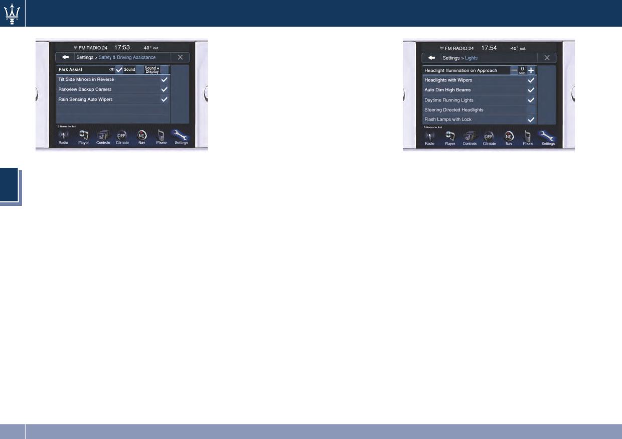
Dashboard Instruments and Controls
• Rain Sensing Auto Wipers
By selecting this feature, the system
will automatically activate the
windshield wipers if it senses
moisture on the windshield.
Lights
Press the Lights soft-key to set the
following modes.
• Headlights Off Delay
• Tilt Side Mirrors In Reverse
By selecting this feature, the driver
• Headlights with Wipers
By selecting this feature the outside
can choose to have the headlights
By selecting this feature, while the
4
side-view mirrors will tilt downward
off or lit for 30, 60, or 90 seconds
headlight lever is in “AUTO”
when the ignition is in RUN position
when exiting the vehicle. To change
position, the headlights will turn on
and the transmission shift lever is in
the current headlight off delay
approximately 10 seconds after the
R (Reverse) position. The mirrors will
status, touch and release the 0, 30,
wipers are activated. The headlights
move back to their previous position
60 or 90 soft-key to select the
will also turn off when the wipers
when the transmission is shifted out
desired time range.
deactivate if they were activated in
of R (Reverse).
the current mode.
• Headlights Illumination on Approach
• ParkView Backup Camera
By selecting this feature, the driver
• Auto Dim High Beams
This vehicle is equipped with the
can choose to have the headlights
By selecting this feature, the high
ParkView® rear backup camera
off or lit for 30, 60, or 90 seconds
beam headlights will deactivate
which allows you to see an image of
when the doors are unlocked with
automatically under certain
the rear surroundings of your
the key fob RKE transmitter.
conditions. See “Lights” in section 3
vehicle whenever the shift lever is
for further information.
set in R (Reverse). The image will be
• Daytime Running Lights
displayed on the MTC display along
When this feature is selected, the
with a caution note to “check entire
DRL lights will turn on whenever the
surroundings”. See “ParkSense®
engine is running. To make your
Park Assist” in section 2 for further
selection, touch the Daytime
information.
Running Lights soft-key, until a
166
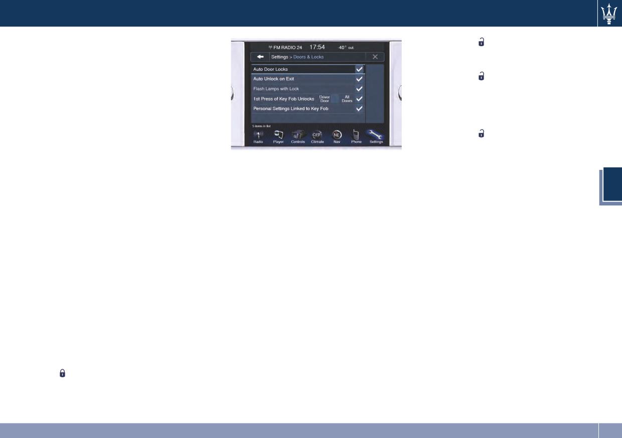
Dashboard Instruments and Controls
check-mark appears next to setting,
transmitter
button. When 1st
showing that setting has been
press of key fob unlocks is selected,
selected.
you must press the key fob RKE
transmitter
button twice to
• Steering Directed Headlights
unlock the passenger's doors. When
By selecting this feature, the
unlock all doors by 1st press
headlights rotate following the
selection mode, all doors will unlock
steering wheel direction change.
on the first press of the key fob RKE
• Headlights Dip (Traffic Changeover)
transmitter
button.
By selecting this feature, the
NOTE:
headlights will change their
• Auto Unlock on Exit
If the vehicle is programmed on 1st
luminous distribution when a
By selecting this feature, all doors
Press of Key Fob Unlocks:
left-hand-drive vehicle enter a
will unlock when the vehicle is
4
Country with right-hand-drive
• all doors will unlock no matter which
stopped, the transmission is in P
system and vice versa.
Passive Entry equipped door handle
(Park) or N (Neutral) position and
is grasped;
• Flash Lamps with Lock
the driver's door is open.
• only the driver’s door will unlock
By selecting this feature, the
• Flash Lamps with Lock
when the driver’s door is grasped;
headlights will flash when the doors
By selecting this feature, the
are locked or unlocked with the key
• with Passive Entry, touching the
headlights will flash when the doors
fob RKE transmitter.
handle more than once will only
are locked or unlocked with the key
result in the driver’s door opening.
Doors & Locks
fob RKE transmitter.
If driver door first is selected, once the
Press the Doors & Locks soft-key to set
• Sound Horn with Lock
driver door is opened, the interior
the following modes.
By selecting this feature, the horn
door lock/unlock switch can be used to
• Auto Door Locks
will sound when the doors are
unlock all doors (or use key fob RKE
locked or unlocked with the key fob
This feature allows you to lock the
transmitter).
RKE transmitter.
vehicle’s door(s) without having to
press the key fob RKE transmitter
• 1st Press of Key Fob Unlocks
button. See “Passive Entry
By operating the 1st Press of the Key
System” in section 2.
Fob Unlocks mode you may set up
only the driver's door will unlock on
the first press of the key fob RKE
167
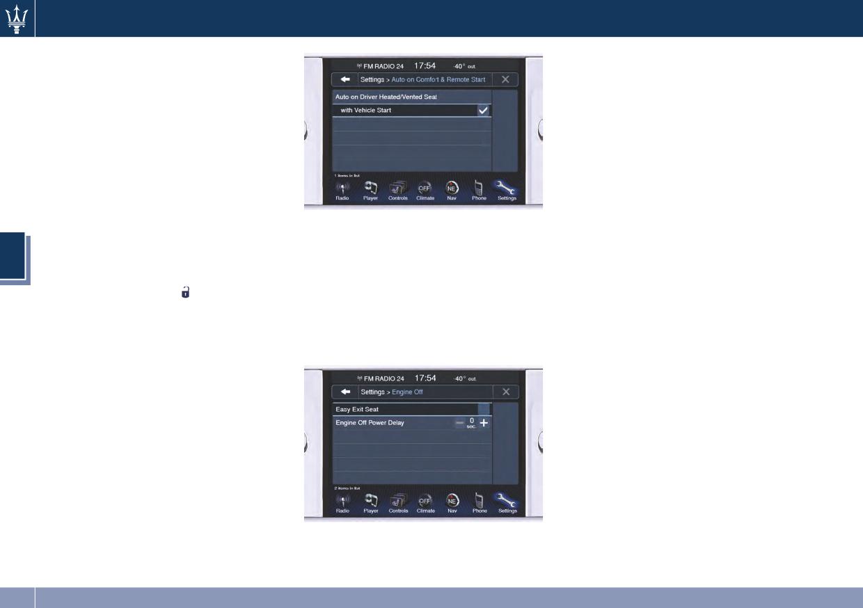
Dashboard Instruments and Controls
• Passive Entry
• Engine off Power Delay (Power
By selecting this feature, Passive
duration after engine shutdown)
Entry may be programmed to on or
By selecting this feature, the power
off. The default status is on. With
window switches, radio, MTC
Passive Entry deactivated, also the
System, DVD video system (for
“Pre-Short Drop” function is
versions/markets, where provided),
disabled (for further information,
power sunroof, and power outlets
refer to “Bodywork Maintenance
will remain active for up to 10
and Care” in section 7).
minutes after the ignition switch is
cycled to OFF. Opening of one front
• Personal Settings Linked to Key Fob
Engine Off
door will cancel this feature.
By selecting this mode, the key fob
The switch-off delay can be canceled
can be programmed with the
This feature allows certain functions
4
(0 seconds) or reduced to 5 minutes
driver’s personal position settings.
after turning off the engine.
or 45 seconds.
These settings will be implemented
• Easy Exit Seat
when pressing the
button on the
• Headlights off delay
This feature provides automatic
remote control.
By selecting this feature the
driver seat positioning to enhance
Auto-On Comfort & Remote Start
headlights will stay lit for up to 90
driver mobility when entering and
seconds after turning off the
By pressing the Auto-on Comfort
exiting the vehicle.
engine.
soft-key the following setting will be
The switch-off delay can be canceled
available.
(0 seconds) or reduced to 60 or 30
• Auto-on Driver Heated/Ventilated
seconds.
Seat & Steering Wheel with Vehicle
Audio
Start
By selecting this feature the driver’s
This feature enables to view and set
heated seat and heated steering
the available audio modes depending
wheel will automatically activate
on the type of audio system supplied
when the temperature is below 40°F
on the car.
(4°C). When temperatures are above
The following modes refer to the
80°F (26°C) the driver vented seat
“High Premium” audio system.
will turn on.
168
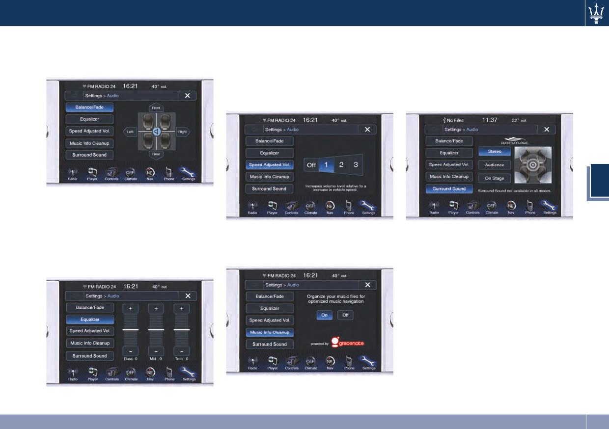
Dashboard Instruments and Controls
• Balance/Fade
• Speed Adjusted Volume
• Surround Sound (only for “High
Use this screen to adjust the Balance
This feature increases or decreases
Premium” audio system)
and Fade settings.
volume combined to vehicle speed.
This feature provides simulated
To change the speed adjusted
surround sound mode. To make
volume touch the Off, 1, 2 or 3
your selection, press Stereo,
soft-key.
Audience or On Stage.
4
• Equalizer
Use this screen to adjust the Bass,
Mid and Treble settings. Adjust the
settings with the + and - setting
• Music Info Cleanup
Phone/Bluetooth
soft-keys or by selecting any point
This feature helps organizing music
Press the Phone/Bluetooth soft-key to
on the scale between the + and -
files for optimized music navigation.
select and connect phones and audio
soft-keys.
sources.
• Paired Phones
• Paired Audio Sources
By selecting one of these options you
will be notified which phones or
which audio sources are combined to
the Phone/Bluetooth system.
For each option, you can also add a
device and change the PIN code of the
device you wish to connect. For
further information, see the MTC
guide.
169
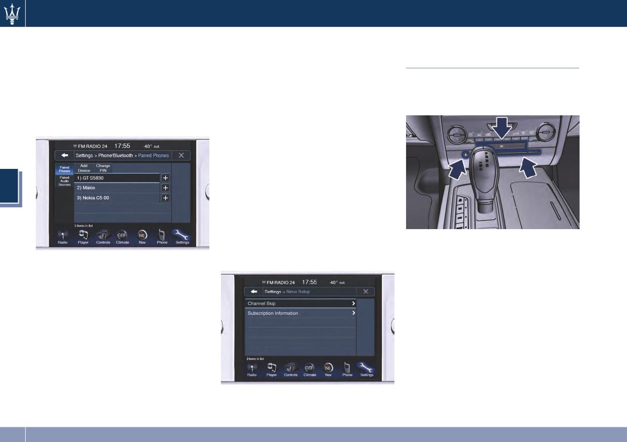
Dashboard Instruments and Controls
NOTE:
would like to skip followed by
Slot for SD Memory Card
pressing the arrow ◄ soft-key.
On the Maserati website, at
and CD/DVD
• Subscription Information
Authorized Maserati Dealer you may
SIRIUS XM Satellite radio requires a
Both slots are located on the center of
consult the list of telephones that are
user-paid subscription to access
the dashboard, under the air
compatible with the MTC, and their
these stations.
conditioning system control devices.
level of compatibility.
It will be necessary to access the
information on the Subscription
Information Screen in order to
subscribe.
Touch the Subscription Info soft key
to access your receiver ID number.
4
Write down the SIRIUS XM ID
numbers for your radio. To activate
SIRIUS XM service, either call the
number listed on the screen or visit
SIRIUS XM online at
To insert a memory card into the slot,
lift the tab with the “SD” indication
SIRIUS XM Setup
call the number listed.
and push it inside the slot. To extract
After pressing the SIRIUS XM Setup
it, press lightly on the card.
soft-key the following settings will be
To insert a CD/DVD push it inside the
available.
lower slot with the label on the upper
side. To extract it, press the button on
• Channel Skip
the left side of the slot, as indicated.
SIRIUS XM can be programmed to
Songs and video played from a SD card
designate a group of channels that
or a CD/DVD can be controlled using
are the most desirable to listen to or
the touch screen controls on the MTC
to exclude undesirable channels
(see the MTC guide) or the remote
while scanning. To make your
controls on the steering wheel (see
selection, touch the Channel Skip
“Audio Controls” in this section).
soft-key, select the channels you
170
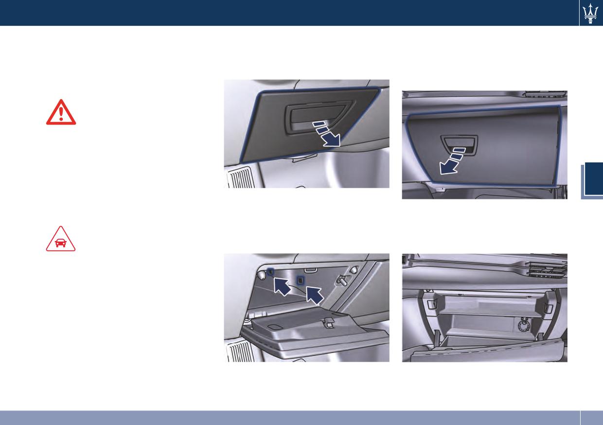
Dashboard Instruments and Controls
Dashboard Compartments
Glove Box Driver Side
Glove Box Passenger Side
To open the glove box on the driver
To open the glove box on the
There are two glove box
side, pull the handle as indicated.
passenger side, pull the handle as
compartments on the dashboard to
shown in the picture.
store small items or documents.
WARNING!
Do not operate the vehicle with a
compartment lid in the open position.
Cellular phones, music players, and
other handheld electronic devices
should be stowed while driving. Use
4
of these devices while driving can
cause an accident due to distraction,
The compartment is ca. 10-12 in (25-30
resulting in death or injury.
cm) deep and is lit by two courtesy
The compartment is divided into two
lights when open (the light
parts: in the lower part you can find
automatically switches off when the
the Owner’s documentation, while in
compartment is closed).
the upper part you can fit small items.
CAUTION!
Do not place objects weighing over
22 lb (10 kg) in the glove box
compartment.
171
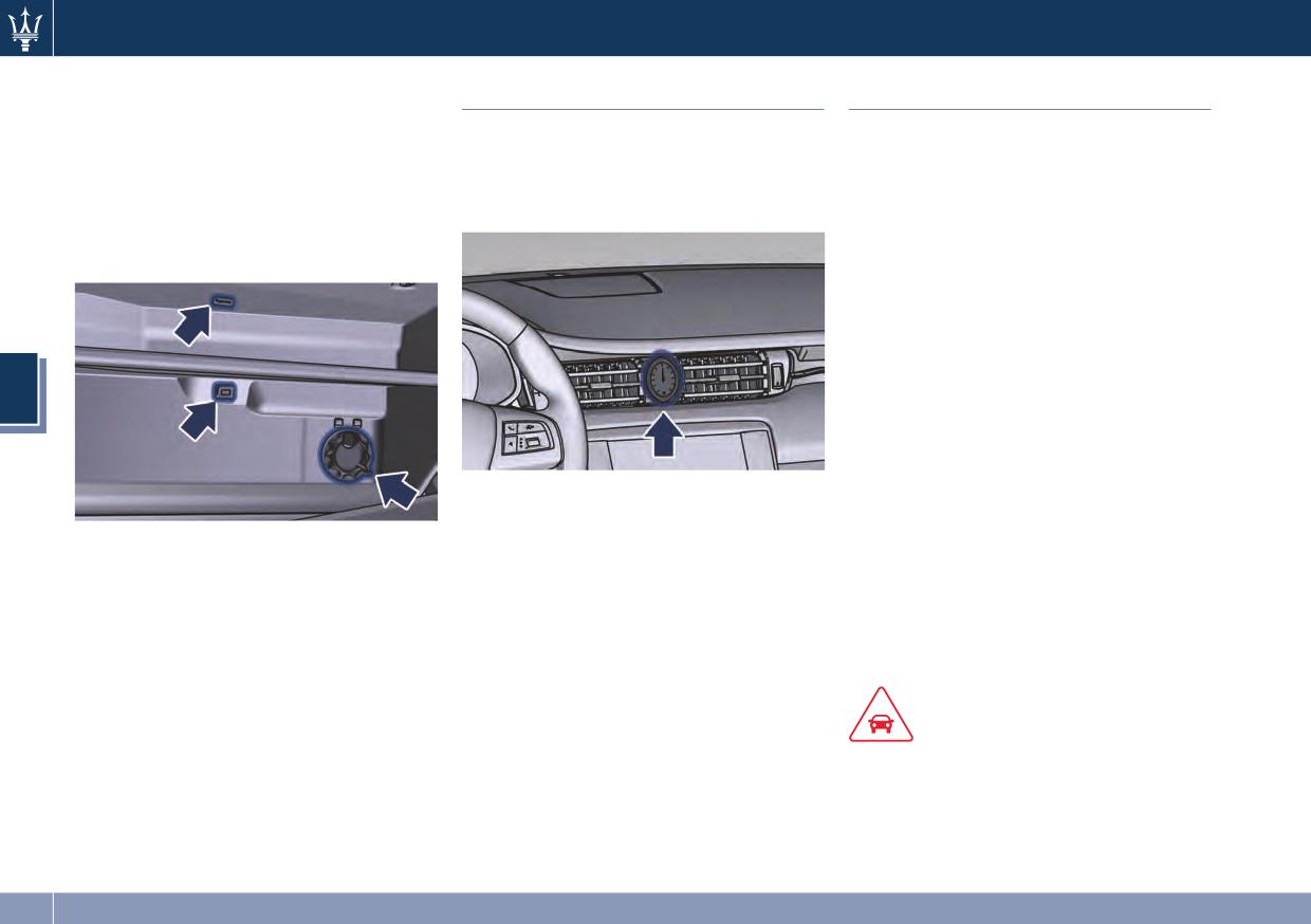
Dashboard Instruments and Controls
The compartment is illuminated by a
Analog Clock
Air Conditioning Controls
courtesy light when open (the light
will automatically switch off when the
To adjust the analog clock located on
The vehicle is equipped with an
compartment is closed); moreover, the
the center of the dashboard between
automatic dual-zone air conditioner/
compartment is also air-conditioned
the air outlets, use the MTC System
heater that adjusts the air temperature
like the rest of the interior.
(see “MTC Settings” in this section).
in the passenger compartment, in two
The air outlet inside the compartment
separate left and right side zones.
is located on the lower right side.
Upon request, the vehicle can be
equipped with an automatic four-zone
air conditioning system: in this case an
additional A/C module, operable both
by the rear and the front passengers
(see “Four-zone Climate Control
4
(optional)” in this chapter), is installed
in the central console, between the
front seats.
A demister system can "control" a
The time can be visualized also on the
specific area of the windshield,
MTC status bar and on the instrument
through a sensor located behind the
cluster display (see “MTC Settings” in
rearview mirror, and activate a special
this section).
function to prevent or eliminate mist.
Clock backlight functioning is
The sensor is enabled upon ignition
combined with the MTC display and
and whenever the user presses one of
the ignition switch backlight.
the automatic function buttons
(AUTO).
CAUTION!
To help ensure proper functioning of
the sensor, do not apply adhesive
parking stickers, etc. in the “sensing”
area between the sensor and the
(Continued)
172
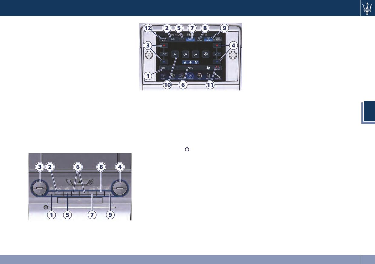
Dashboard Instruments and Controls
(Continued)
indicator illuminates when the A/C is
windshield. Therefore, keep the
on. Operating this function will cause
windshield and the sensor clean to
the automatic feature to switch into
prevent accumulation of dust or other
manual mode and the AUTO LED/Key
impurities.
will turn off.
3. Driver temperature control
Dual Zone Climate Controls
Provides the driver with independent
This system can be operated by using
temperature control. Push the ▼
either the automatic climate control
button for cooler temperature. Push
panel on the dashboard, below the
the ▲ button for warmer
MTC display, or the corresponding soft
Description of Controls
temperature. The driver's temperature
keys on the MTC display.
All functions, except the air
setting will be displayed on the MTC
When the MTC System is in any mode
distribution, MAX A/C and the SYNC
screen between the arrows.
4
other than climate (Radio, Player,
mode, can be set and modified using
NOTE:
Controls, etc.) the driver and
the climate control panel or the MTC
In SYNC mode, this button will also
passenger temperature settings will be
display.
automatically and simultaneously
indicated on the upper part of the
1. Climate control on/off
adjust the passenger temperature.
display.
Press the button
or the OFF key to
switch the climate control on/off. The
4. Passenger temperature control
LED on the button and the OFF key
Provides the passenger with
will illuminate when the A/C is on.
independent temperature control.
Push the ▼ button for cooler
NOTE:
temperature. Push the ▲ button for
For vehicle equipped with Remote
warmer temperature. The passenger's
Start, the Air Conditioning System will
temperature setting will be displayed
not function during Remote Start
on the MTC screen between the
operation if the climate control is left
arrows.
in OFF.
NOTE:
2. A/C
Pressing the 4 button while in SYNC
Press to change the current air
mode will automatically exit SYNC.
conditioning (A/C) setting; the
173
Dashboard Instruments and Controls
5. Recirculation
when the AUTO function is activated.
Press to change the current setting,
See “Automatic Temperature Control
CAUTION!
the LED indicator on the button/the
(ATC)” in this chapter for more
relevant soft key illuminates when the
information.
Failure to observe the following
function is on.
cautions may cause damage to the rear
8. FAST defrosting/demisting
windows defroster:
6. Blower control
Press the
button/the
soft key to
Blower control is used to regulate the
switch the airflow setting to the
• Use care when washing the inside of
amount of air forced through the
windshield and the front side windows
the rear window. Do not use abrasive
climate system. There are seven blower
to get a quick defrosting/defogging.
window cleaners on the interior
speeds available. Adjusting the blower
The LED on the button/the soft key
surface of the window. Use a soft
will cause automatic mode to switch to
illuminates when this feature is
cloth and a mild washing solution,
manual.
activated. Operating this function will
wiping parallel to the heating
Pushing the “+” on the climate control
cause the ATC to switch into manual
elements. Labels can be peeled off
4
panel will increase the speed of the
mode: so the AUTO LED/soft key will
after soaking with warm water.
blower, while pushing the “-” will
turn off; the fifth blower speed will be
• Do not use scrapers, sharp
decrease it. On the MTC screen, touch
automatically selected, unless the
instruments, or abrasive window
the small icon of the blower to
blower is not already set to a higher
cleaners on the interior surface of
decrease the speed, or the big icon to
speed. If this function is turned off the
the window.
increase it. Between the two icons,
climate system will return to the
• Keep all objects inside the vehicle at
bars will appear to show the number
previous setting.
a safe distance from the window.
of the corresponding selected speed.
9. REAR defrosting/demisting
The blower can also be activated/
10. Airflow distribution modes
Press the
button/the
soft key to
regulated by touching the bars
The airflow distribution mode can be
turn on the rear window defroster and
between the two blower icons.
adjusted so air comes from the
the heated outside mirrors. A LED
dashboard vents, floor vents,
7. AUTO
indicator will illuminate when the rear
demist/defrost vents.
This function automatically controls
window defroster and the heated
The mode setting keys are located on
the interior temperature by adjusting
external mirrors are on.
the MTC display only and allow
the air flow rate and the air
The rear window defroster and the
following setting options:
distribution. Press the AUTO will cause
heated external mirrors automatically
the ATC to switch between manual
turn off after 10 minutes.
• “Dashboard” mode
and automatic mode. The LED on the
Air flows in from the four adjustable
button/the AUTO soft key illuminates
vents of the dashboard and the two
174
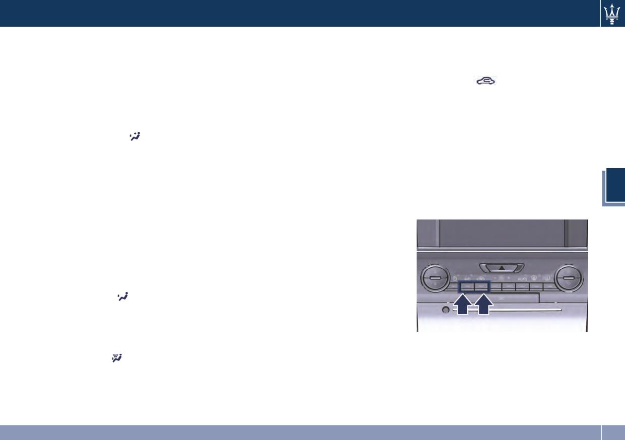
Dashboard Instruments and Controls
positioned at the rear of the central
improve comfort and prevent
When the A/C and AUTO are switched
console. Each of these vents can be
fogging.
off it is not possible to have air at a
singly adjusted. The air vanes of the
lower temperature than the outside.
11. “SYNC” mode
vents can be moved up and down or
Press the SYNC soft-key on the MTC to
Recirculation
right and left to adjust air flow
switch the Sync feature on/off. The
When outside air contains smoke,
direction. A setting wheel, placed
SYNC indicator illuminates when this
odors, or high humidity, or if rapid
near each vent, allows to regulate
feature is selected. This function is
cooling is desired, you may wish to
or close the air flow.
used to synchronize the passenger
recirculate interior air by pressing the
• “Bi-Level” mode
temperature setting with the driver
Recirculation control button. The LED
Air comes from the dashboard
temperature setting.
on the button/the recirculation soft
vents, the central console adjustable
Changing the passenger temperature
key will illuminate when this function
vents and the fixed floor vents. A
setting while in SYNC will
is selected. Push the button a second
small portion of the airflow is
automatically exit this feature.
time to turn off the Recirculation
4
directed through the defrost/demist
mode and allow the entry of outside
12. MAX A/C
vents.
air into the air conditioning system.
Pressing the MAX A/C soft key on the
NOTE:
MTC, the system automatically
switches to get the maximum cold air
Bi-Level mode is designed to let cooler
flow.
air from the dashboard and rear
central console vents and warmer air
Dual Zone Climate Control
from the floor vents.
Functions
Air Conditioning (A/C)
• “Floor” mode
The A/C button allows to manually
Air comes from the floor vents. A
activate or deactivate the air
small portion of the airflow is
conditioning system. When the air
directed through the defrost/demist
conditioning system is turned on, cool
vents.
dehumidified air will flow through the
• “Mix” mode
vents into the cabin. For improved fuel
Air comes from the floor and the
economy, press the A/C button to turn
defrost/demist vents. This mode is
off the air conditioning and manually
recommended for cold climates, to
adjust the blower and airflow mode
settings.
175
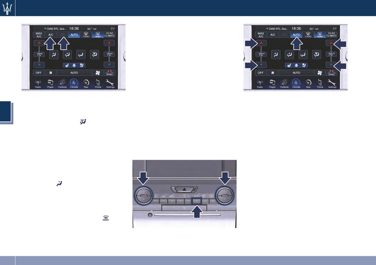
Dashboard Instruments and Controls
Automatic Temperature Control
(ATC)
Automatic operation
• Press the AUTO key on the A/C panel
or the soft key button on the MTC
screen.
• Set the desired temperature
adjusting the driver and/or passenger
temperature hard or soft control
NOTE:
buttons. Once the desired
• To provide you with maximum
temperature is displayed, the system
comfort in the Automatic mode,
In cold weather, use of Recirculation
will achieve and automatically
during cold start-ups the blower
4
mode may lead to window fogging.
maintain that comfort level.
speed will remain low until the
Select the MIX mode
and increase
• When the system is set up for your
engine warms up.
the blower speed to prevent fogging.
comfort level, it is not necessary to
Manual operation
change the settings anymore, simply
MAX A/C
The system allows manual selection of
allow the system to function
Activating this function, the system
blower speed, air distribution mode,
automatically.
switches to exit AUTO, enter A/C and
A/C status and Recirculation control.
Recirculation. The minimum
The blower fan speed can be set to any
temperature (LO) in both zones, the
fixed speed by adjusting the blower
maximum blower speed and the air
control. In this case the blower will
distribution
are also selected.
operate at a fixed speed until
The blower speed can be adjusted and
additional speeds are selected. This
the air distribution can be modified
allows the front occupants to control
without exiting MAX A/C. To exit MAX
the volume of air circulated in the
A/C press the relevant soft key or exit
vehicle and cancel the AUTO mode.
A/C or Recirculation. Selecting
,
The user can also select the direction
AUTO, or OFF, will also exit MAX A/C.
of the airflow by selecting one of the
available mode settings. A/C operation
and Recirculation control can also be
manually selected.
176
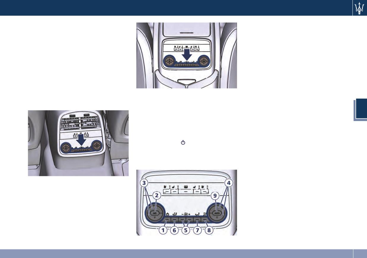
Dashboard Instruments and Controls
Four-Zone Climate Control
2. A/C
Press to change the current air
(optional)
conditioning (A/C) setting, the A/C
Air conditioning controls that allow
symbol on the button illuminates
rear passengers to adjust the
when the A/C is on. This will cause the
temperature in the left and right rear
automatic operation to switch into
part of the passenger compartment
manual mode and the AUTO indicator
are located at the rear of the center
will turn off.
console underneath the adjustable air
3. Left side temperature control
outlets, or on the rear console storage
Provides the rear passengers with
compartment between the rear seats,
“Comfort Luxury" Rear Seats
independent temperature control.
if the vehicle is equipped with
Push the ▼ button for cooler
“Comfort Luxury" seats.
Description of Controls
temperature settings or the ▲ button
4
The following functions can be
for warmer temperature. The set
operated/adjusted by using the rear
temperature value will be displayed in
climate control panel.
the area above the buttons.
1. Rear climate control on/off
4. Right side temperature control
Press the button
to switch the rear
Provides the rear seats passengers
climate control on/off. The LED on the
with independent temperature
button turns on when the rear A/C is
control. Push the ▼ button for cooler
on.
temperature settings or the ▲ button
for warmer temperature. The set
temperature value will be displayed in
the area above the buttons.
5. Blower control
Blower control is used to regulate the
airflow of the rear climate system.
There are seven blower speeds
available. Adjusting the blower will
cause the automatic mode to switch to
manual.
177
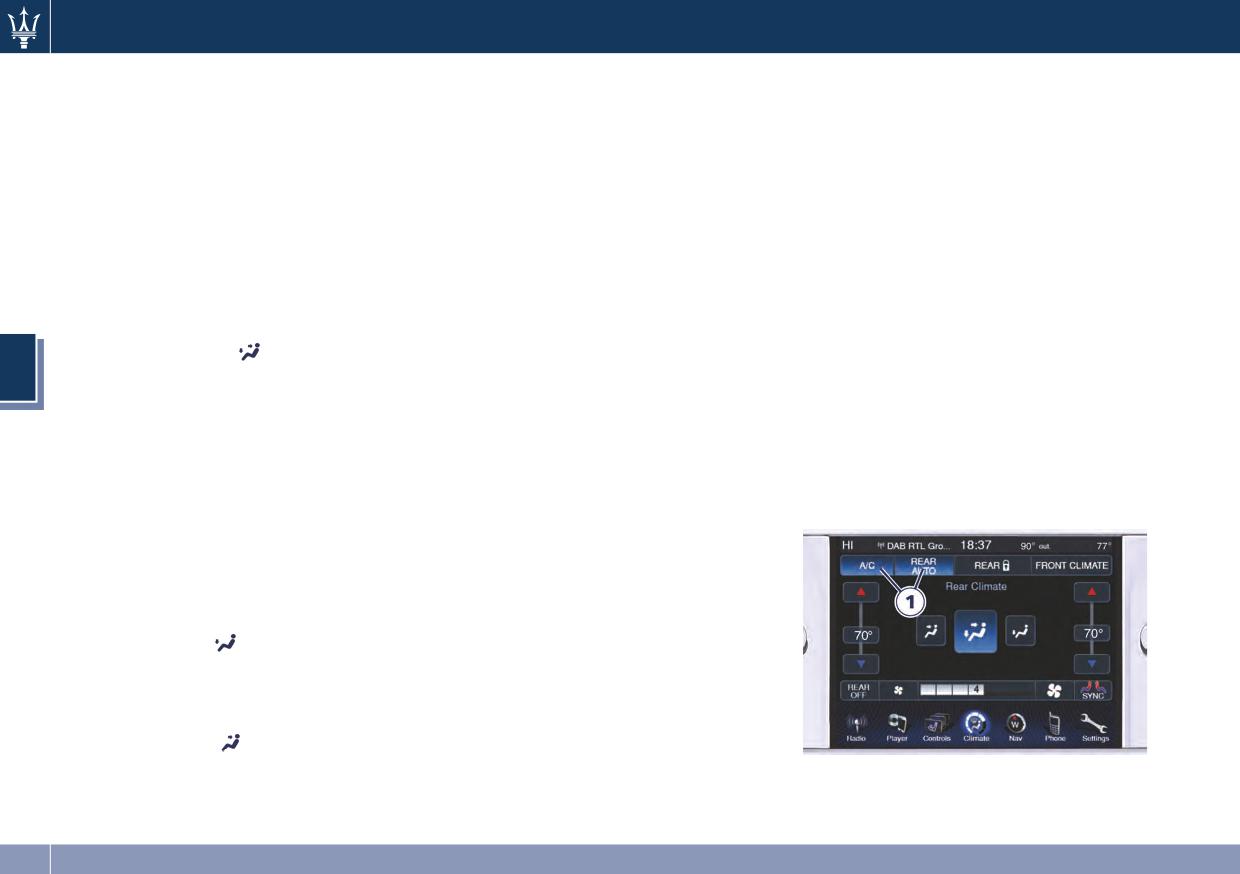
Dashboard Instruments and Controls
Press the “+” button to increase
vanes of the vents can be moved up
Four-Zone Climate Control by the
blower speed.
and down or right and left to adjust
Driver
Press the “-” button for lower speed.
air flow direction. A setting wheel,
By operating the MTC display controls
placed near each vent, allows to
Airflow distribution modes
the driver can adjust the settings of
regulate or close the air flow.
The airflow distribution can be
the rear climate zones controlled by
adjusted to let air come from the
9. AUTO
rear passengers.
central console vents, floor vents,
This function automatically controls
By touching the following MTC screen
demist/defrost vents on pillars
the interior temperature by adjusting
keys, the driver is able to:
between the doors. The set mode is
the air flow rate and the air
1.
View and change the settings of
recognizable through an illuminated
distribution.
the rear climate.
LED on the button.
• Press the AUTO button: the
2.
Block the settings of the rear
6. “Bi-Level” mode
automatic rear climate control
climate.
4
Air comes from the adjustable vents on
switches from manual to automatic
3.
Synchronize the temperature of
the rear central console and from the
mode and vice-versa. The AUTO
the passenger side with the
fixed ones directed to the floor. A
symbol on the button illuminates
driver's side.
portion of the airflow is directed to
when this function is activated.
4.
Return to the front climate
the vents on pillars.
• Adjust then the temperature you
control display.
wish to maintain by regulating the
NOTE:
left and/or right side temperature
The Bi-Level mode is designed to
control buttons. Once the desired
provide comfort by sending cooler air
temperature is set, the system will
out of the central console vents and
achieve and automatically maintain
warmer air from the floor vents.
that comfort level.
• When the system is set up for your
7. “Floor” mode
comfort level, it is not necessary to
Air comes from the floor vents. A
change the settings anymore: simply
portion of the airflow is directed to
allow the system to function
the vents on pillars.
automatically.
8. “Panel” mode
To provide you with maximum comfort
Air comes from the adjustable vents on
in the Automatic mode, during cold
the central console. Each of these
start-ups the blower speed will remain
vents can be singly adjusted. The air
low until the engine warms up.
178
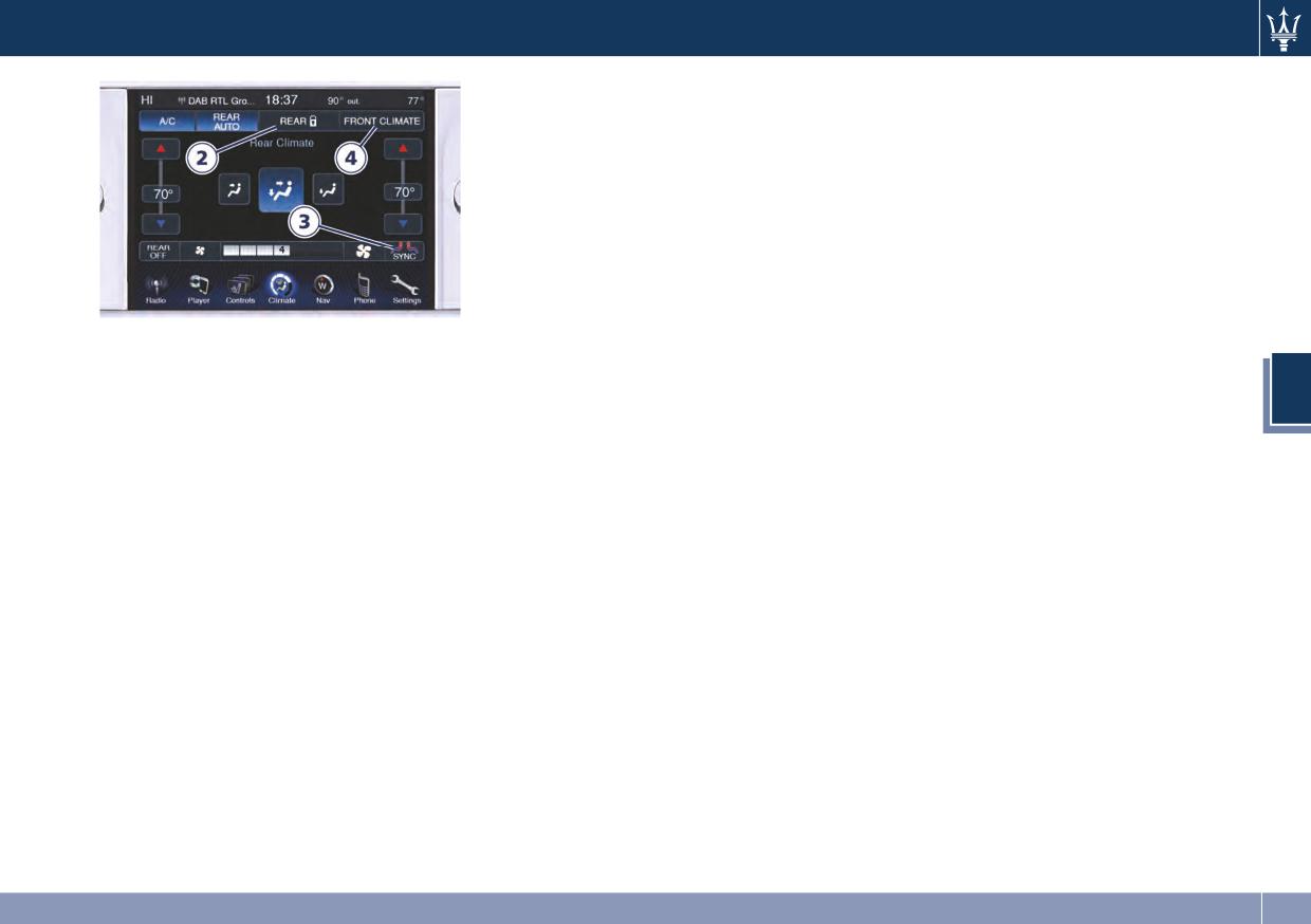
Dashboard Instruments and Controls
• Automatic Temperature Controls
• Any time you store your vehicle or
(ATC) will automatically adjust the
keep it stationary (i.e., during
climate control settings to reduce or
vacation) for two weeks or more,
eliminate window fogging on the
run the air conditioning system at
front windshield.
idle for about five minutes in the
fresh air by high blower setting. This
• Make sure the air intake, located
will ensure adequate system
directly in front of the windshield, is
lubrication and minimize the
free of obstructions such as leaves or
possibility of compressor damage
other objects. Leaves collected in the
when the system is started again.
air intake may reduce airflow, and if
Operating Tips
they enter the plenum, they could
• Continuous use of the air
plug the water drains. In winter
4
recirculation in winter, in rainy
make sure the air intake is clear of
weather or humid climate is not
ice, slush, and snow.
recommended because it may cause
• The climate control system filters
window fogging.
outside air containing dust, pollen
• Interior fogging on the windshield
and some odors. Strong odors
can be quickly removed by FAST
cannot be totally filtered out. See
defrosting/demisting. The “Mix”
“Maintenance Procedures” in section
mode can be used to maintain a
7 for filter replacement instructions.
clear windshield and provide
• The temperature can be displayed in
sufficient heating. If side window
U.S. or Metric units by selecting the
fogging becomes a problem increase
US/M customer programmable
blower speed.
feature. See “MTC Settings” in this
NOTE:
section.
• Recirculation mode without A/C
should not be used for long periods
of time, as fogging may occur.
179
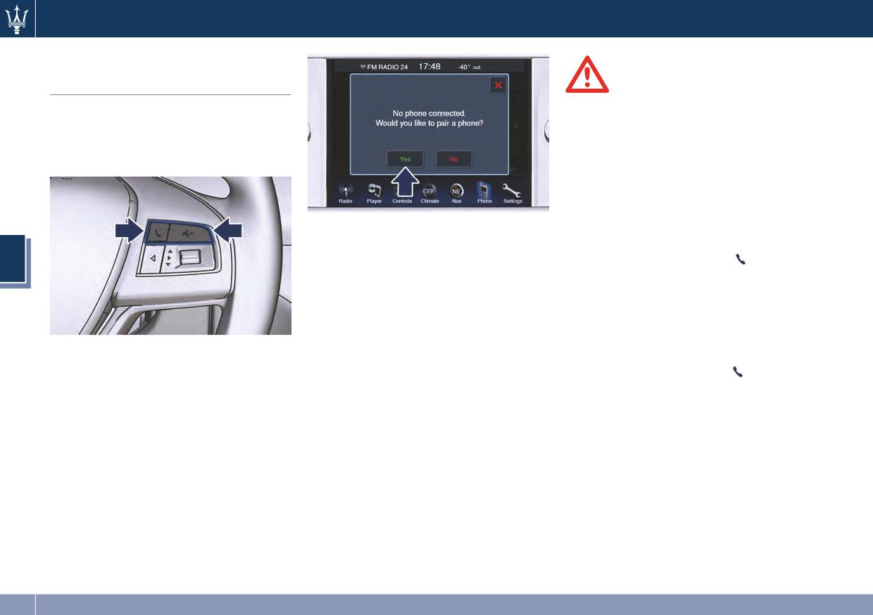
Dashboard Instruments and Controls
Phone and Voice Controls
on Steering Wheel
WARNING!
Any voice-controlled system should be
The controls on the right side of the
used only in safe driving conditions
steering wheel activate/deactivate the
following all applicable regulations.
phone mode and the voice control
All attention should be kept on
functions.
driving. Failure to do so may result in
a collision causing serious injury or
death.
The voice command communication
Phone Mode
system is fully integrated with the
4
vehicle's audio system.
By using the Phone button
it is
The volume can be adjusted from the
possible to: activate the phone mode,
radio volume control knob on the side
start a call, show recent incoming and
of the MTC screen or from the steering
outgoing calls, show contact list, etc.
wheel radio controls (see “Audio
All these functions can also be reached
Controls” in this section).
by using the touch screen commands
These functions are only available
The system will automatically mute the
on the MTC screen.
when one or more Bluetooth®
radio when using the phone mode.
When pressing the button
an
compatible mobile phones are paired
When activating the phone mode
audible sound will indicate system
with the MTC System connection: to
using voice commands with
readiness to accept a command.
pair a phone and to learn all available
speakerphone, you should speak
functions refer to the MTC guide.
normally in a conversational tone from
NOTE:
the driver’s position towards the front
dome light where the voice command
On the Maserati website, at
system microphone is located.
System recognition of the user’s voice
Authorized Maserati Dealer you may
can decrease when the speaking too
consult the list of telephones that are
quickly or too loudly.
compatible with the MTC, and their
level of compatibility.
180
Dashboard Instruments and Controls
Voice Commands
By using voice commands, after
pressing the
button, it is possible
to control the AM and FM radio, the
satellite radio and all other media or
devices connected to and controlled
by the “Player” mode (i.e CD player,
SD card, USB/iPod player).
When pressing the
button, an
acoustic signal will indicate the system
is ready to accept a voice command.
NOTE:
4
For further details refer to the
Maserati Touch Control guide.
181
5 - Driving
Normal Starting of the Engine
184
Automatic Transmission
186
Drive Mode
192
Parking Brake
198
Parking
201
Brake and Stability Control System
203
Using the Brakes
206
Use of the Engine
206
Electronic Cruise Control
208
Tires - General Information
211
Tire Pressure Monitoring System (TPMS)
220
Fuel Requirements
225
Refueling
227
Driving Conditions
229
183
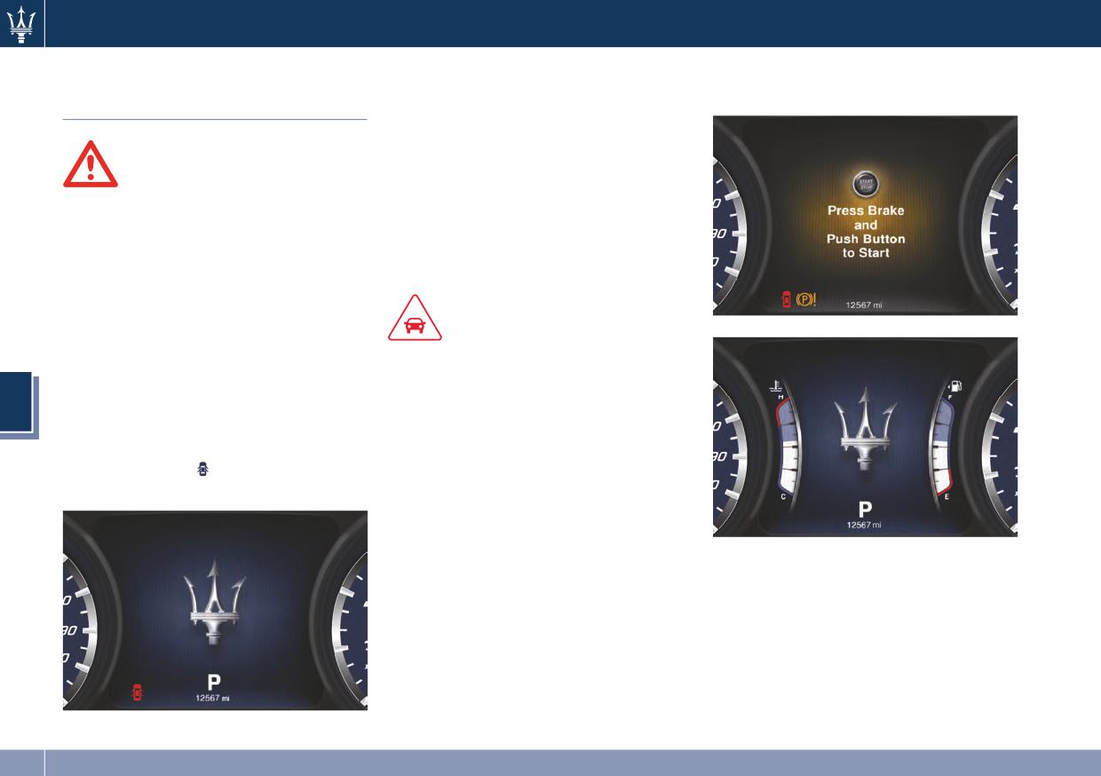
Driving
Before starting the engine, close the
gages, Maserati logo and complete
Normal Starting of the
doors, adjust your seat, the inside and
odometer, will display.
Engine
outside mirrors, fasten your seat belt
and instruct all other occupants to
buckle their seat belts.
WARNING!
The shift lever must be in P (Park) or N
(Neutral) position before you can start
• Hold the brake pedal down when
the engine. Apply the brakes before
starting the engine.
shifting into any driving gear (see
• It is dangerous to run the engine in
“Automatic Transmission” in this
an enclosed area. The engine
section).
consumes oxygen and discharges
carbon dioxide, carbon monoxide
and other toxic gases in the
CAUTION!
atmosphere.
• Before starting the engine, switch off
the electrical devices with a high
When doors are opened, the
5
instrument cluster displays the
power consumption (air-conditioning
and heating system, heated rear
Maserati Logo in the center and the
window, headlights, etc.).
complete odometer plus the “open
doors” indicator
in the lower part
• Do not start the engine if the fuel
of the cluster.
level in the tank is low.
The keyless ignition device allows the
driver to operate the ignition switch
The current display subsequently sets
by pushing a button, as long as the key
up with the latest screenshot.
fob RKE transmitter is within the
If the engine fails to start, the starter
passenger compartment (check “Keys”
will disengage automatically after 10
in section 2 for further information).
seconds. If you wish to stop the
By pressing the brake pedal and
cranking of the engine prior to
pushing the START/STOP button the
starting it, press the button again.
engine starts and the shift lever
position, engine temperature, fuel
184
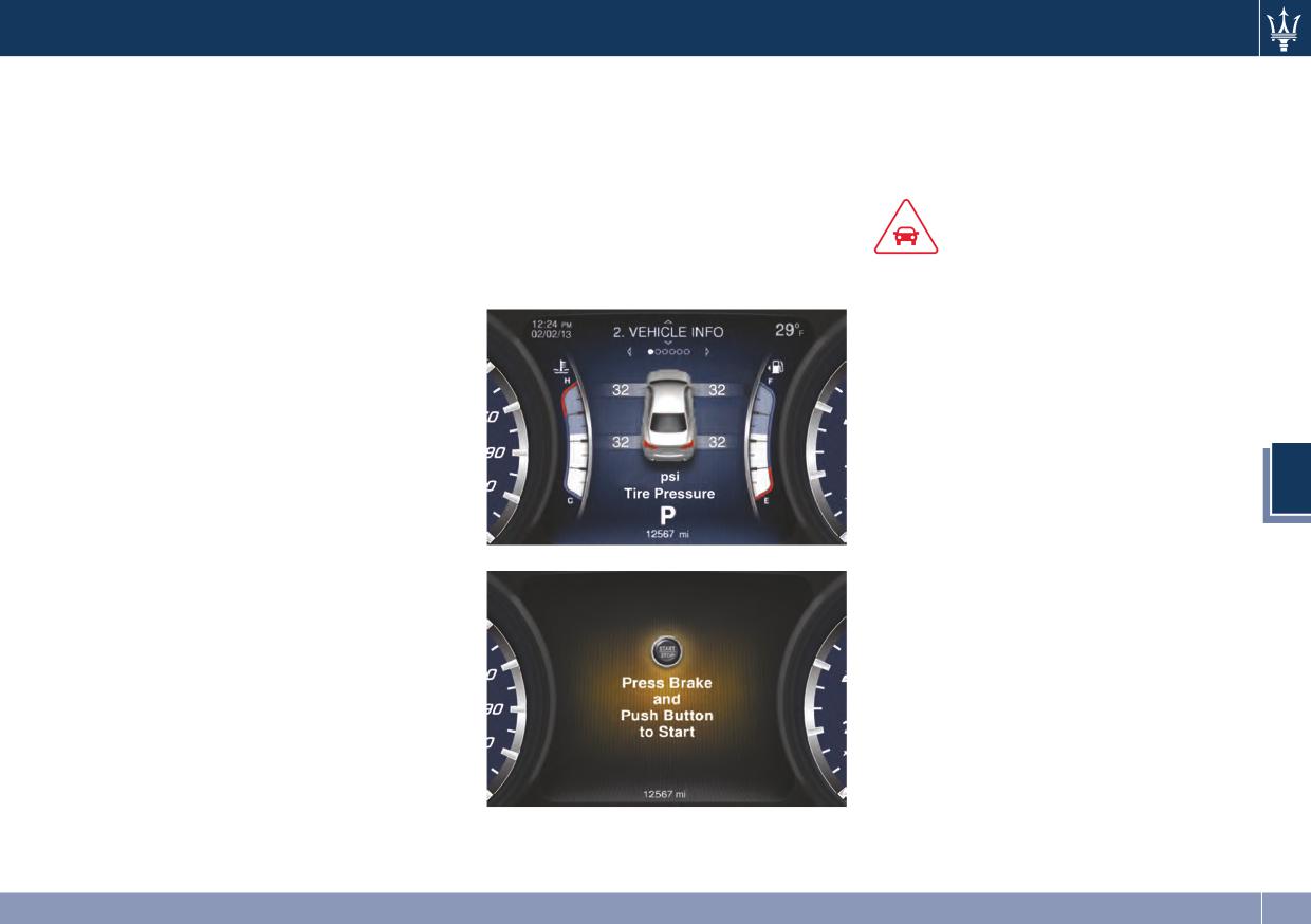
Driving
NOTE:
NOTE:
After starting the engine, the idle
speed is controlled automatically and
Normal starting of either a cold or a
If the ignition switch is left in the ACC
will decrease as the engine warms up.
warm engine is obtained without
or RUN (engine not running) position
pumping or pressing the accelerator
and the transmission is in P (Park), the
Engine Start Failure
pedal.
system will automatically time out
after 30 minutes of inactivity and the
If the driver only pushes the
ignition will switch to the OFF
CAUTION!
START/STOP button but does not press
position.
the brake pedal, the ignition switch
• Do not attempt to push or tow your
cycles to the ACC position (see “Keys”
vehicle to get it started. Vehicles
in section 2) and the instrument
equipped with an automatic
cluster displays the screenshot.
transmission cannot be started this
At the second press of the
way. Unburned fuel could enter the
START/STOP button, the ignition
catalytic converter and once the
device switches to RUN position (see
engine has started, ignite and
“Keys” in section 2) and the
damage the converter and vehicle.
instrument cluster displays the latest
• If the vehicle battery is dead, booster
5
screenshot.
cables may be used to obtain a start
At the third press of the START/STOP
from a booster battery or the
button the ignition switch returns to
battery in another vehicle. This type
OFF position and the display powers
of start can be dangerous if done
down.
improperly. See “Auxiliary Jump
At the fourth press of the START/STOP
Start Procedure” in section 6 for
button the screen will display the
further information.
following message: “Press Brake and
Push Button to Start”.
Flooded engine clearing
If the engine fails to start after you
have followed the described
procedures, it may be flooded. To clear
any excess fuel, move the shift lever in
P (Park) position. Press and hold the
brake pedal, push the accelerator all
the way to the floor and hold it, then
185
Driving
press and release the START/STOP
switch will remain in the ACC
Automatic Transmission
button once. The starter will engage
position until the shift lever is in P
automatically, run for 10 seconds, and
(Park) and the button is pressed
The electronic shift lever replaces the
then disengage. Once this occurs,
twice from the OFF position.
conventional mechanical lever and has
release the accelerator pedal and the
no mechanical connection to the
• If the shift lever is not in P (Park) and
brake pedal, wait 10 to 15 seconds,
transmission. The transmission is
the START/STOP button is pressed
then repeat the “Normal starting of
operated by electrical actuators on the
once, the instrument cluster will
the engine” procedure.
hydraulic system and all commands to
display a “Vehicle Not in Park”
the control system are transmitted by
Starting by cold engine
message and the engine will remain
the CAN network. The lever itself
Start-off slowly, avoiding sudden
running.
represents a mere user interface. Gear
acceleration and rev the engine at low
positions are simulated by solenoids
medium speeds. High-performance
inside the lever body, which are
driving should be avoided until the
WARNING!
computer controlled and enable or
engine temperature reaches 149-158°F
Never leave a vehicle out of the P
disable certain positions of the lever.
(65-70°C ).
(Park) position, as it could roll away.
The solenoids inside the gear lever
Engine Turn Off
prevent the movement of the lever
5
NOTE:
towards invalid positions.
• Place the shift lever in P (Park) (see
If the ignition switch is left in the ACC
The electronically-controlled
“Automatic Transmission” in this
or RUN (engine not running) position
transmission provides a precise shift
section).
and the transmission is in P (Park), the
schedule. The transmission electronics
• With the engine at idle, press and
system will automatically time out
are self-calibrating, therefore the
release the START/STOP button. The
after 30 minutes of inactivity and the
gearshift behavior could become
ignition switch will return to the OFF
ignition will switch to OFF position.
perfect as expected after few
position. A burst on the accelerator
hundreds of miles.
pedal before turning off the engine
has no purpose and increases fuel
consumption.
CAUTION!
• If the shift lever is not in P (Park), the
In order to properly use the Automatic
START/STOP button must be held for
Transmission, it is essential that you
two seconds and vehicle speed must
read through the whole chapter, so
be above 5 mph (8 km/h) before the
that you can understand right from
engine will shut off. The ignition
(Continued)
186
Driving
(Continued)
forward or in reverse. You could lose
• Do not leave the key fob in or near
the start what the correct and granted
control of the vehicle and hit
the vehicle. A child could operate
operations are.
someone or something. Only shift
power windows, other controls, or
Damage to the transmission may occur
into gear when the engine is idling
move the vehicle.
if the following precautions are not
normally and when your foot is
This vehicle is equipped with a feature
observed:
firmly pressing on the brake pedal.
which requires the shift lever to be
• Unintended movement of a vehicle
• Shift into P (Park) only after the
placed in P (Park) before the engine
could injure those in or near the
vehicle has come to a complete stop.
can be turned off. This prevents the
vehicle. As with all vehicles, you
This is the default position of the
driver from inadvertently leaving the
should never exit a vehicle while the
lever and should be used every time
vehicle without first placing the
engine is running. Before exiting a
the ignition switch is cycled to OFF.
transmission in P (Park). This system
vehicle, always apply the electronic
also locks the shift lever in P (Park)
• Shift into or out of R (Reverse) only
parking brake, shift the transmission
whenever the ignition switch is in the
after the vehicle has come to a
into P (Park), and turn the engine
OFF position.
complete stop and the engine is at
off. The shift lever will consequently
idle speed.
lock in P (Park) position for a few
Automatic Transmission
• Do not shift between P (Park), R
seconds, then eases, handling the
Controls
5
(Reverse), N (Neutral) or D (Drive)
change to prevent the motion of the
Automatic transmission is operated by
when the engine is above idle speed
car.
a selection lever with lock button and
• To effect any change from vehicle
• Never leave children unattended in a
by a series of buttons located on the
stop to R (Reverse), D (Drive), 1st or
vehicle, or with access to an
central console.
2nd gear, it is necessary to keep the
unlocked vehicle. Allowing children
Using the selection lever it is possible
brake pedal fully depressed.
in an unattended vehicle is
to select following positions, indicated
dangerous for a number of reasons.
on the top of the lever: the selected
A child or others could be seriously
position will illuminate in amber light.
or fatally injured. Children should be
WARNING!
• P (Park);
warned not to touch the parking
• It is dangerous to move the shift
• R (Reverse);
brake, brake pedal or the shift lever.
lever out of P (Park) or N (Neutral) if
• N (Neutral);
• When leaving the vehicle, always
the engine speed is higher than idle
remove the key fob and lock your
• D (Drive) automatic forward speed (8
speed. If your foot is not firmly
vehicle.
ranges);
pressing on the brake pedal, the
vehicle could accelerate quickly
187
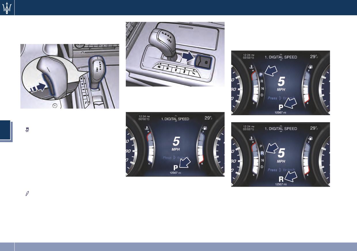
Driving
• +/- to upshift or downshift when
By operating instead the lever, the
manual mode in D (Drive) status, or
new range will be indicated in the
set M (Manual) mode.
field and in the lower part of the
display.
Transmission status is visible on the
lever and on the lower part of the
Instrument cluster display.
Buttons on the central console have
following functions:
•
to exclude/reactivate the ESC
5
system.
• M (Manual): to switch from
automatic to manual driving mode.
• I C E: to activate/deactivate the
driving mode in slippery surfaces
conditions.
• SPORT: to activate/deactivate a
By pressing the release button on the
sportier driving mode.
lever, the gear position field is
•
to switch between the two
If the vehicle is temporarily in the
displayed: if you release the button
suspensions setting modes.
manual drive mode, D2 (Drive) status,
without moving the lever, the field
By selecting one of these functions,
or in M1 (Manual) drive mode, the
disappears after 2 seconds.
the LED beside the button illuminates.
gear position is indicated beside the
The Electric Parking Brake lever is part
lever status, on the lower part of the
of the shift control panel (see “Parking
display.
Brake” in section 5).
188
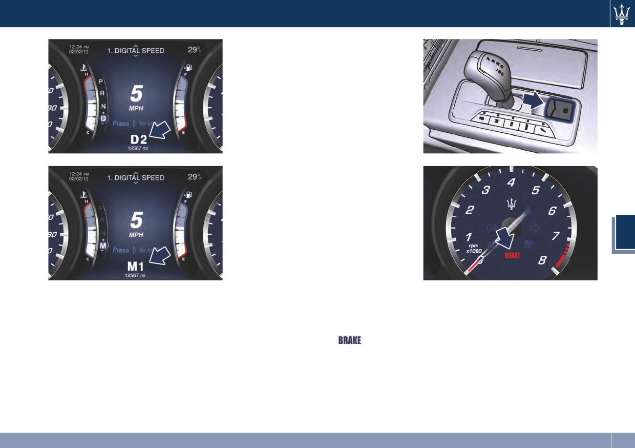
Driving
the vehicle is stopped. Be sure to keep
your foot pressed on the brake pedal
when moving the shift lever between
these gears.
DO NOT race the engine when shifting
from P (Park) or N (Neutral) into
another gear range.
Automatic Transmission Range
P (Park)
Use this position to park the vehicle.
Shifting gears from P (Park) position is
only possible with the brake pedal
pressed. To move the shift lever from P
(Park) position to any other position,
the engine must be switched on. The
engine can be regularly started in P
5
(Park) range. Never attempt to use P
(Park) while the vehicle is in motion.
When parking on a level surface, you
may place the shift lever in the P
In normal conditions, the shift lever is
When parking on a hill, apply the
(Park) position first, and then apply
always unlocked. When in D (Drive)
parking brake before placing the shift
the electronic parking brake by
mode it is possible to upshift or
lever in P (Park).
pulling the handle upwards. The
downshift the changing gears by
For enhanced security, turn the front
Instrument cluster will display the
automatically temporary setting in M
wheels toward the curb on a downhill
related light indicator
and the
(Manual) mode.
and away from the curb on an uphill
message for 5 seconds.
You must also press the brake pedal to
grade.
shift the transmission out of P (Park)
position.
Shifting from D (Drive) to P (Park) or R
(Reverse) should be done only after
the accelerator pedal is released and
189
Driving
R (Reverse)
only possible if the vehicle is moving
forwards.
This range is used to move the vehicle
WARNING!
Set the parking brake and shift the
backward.
• Never use the P (Park) position as a
transmission into P (Park) if you must
We recommend to shift into R
substitute for the electronic parking
leave the vehicle.
(Reverse) only after the vehicle has
brake. Always apply the parking
come to a complete stop.
brake fully when parked to prevent
vehicle movement and possible
• Vehicle halted: switching between P
WARNING!
injury or damage.
(Park), R (Reverse) and D (Drive)
Do not switch to N (Neutral) and/or
requires pressing the unlock button
• Make sure the transmission is in P
never turn off the ignition to coast
on the lever and brake pedal: N
(Park) before leaving the vehicle.
downhill. These are unsafe practices
(Neutral) is reached only by pressing
that limit driver’s response to
the unlock button on the lever.
changing traffic or road conditions. It
• Vehicle moving: the driver can switch
CAUTION!
is possible to lose control of the
from R (Reverse) to N (Neutral), or
vehicle and have a collision.
• DO NOT race the engine when
vice versa, by pressing the lock
shifting from P (Park) or N (Neutral)
button on the shift lever.
5
into another gear range, as this can
N (Neutral)
damage the drivetrain.
CAUTION!
• Vehicle halted and engine started:
Towing the vehicle, coasting, or
• The following indicators should be
switching from N (Neutral) to R
driving for any other reason with the
used to ensure that you have
(Reverse), P (Park) and/or D (Drive)
transmission in N (Neutral) can result
engaged the shift lever into the P
requires brake pedal and unlock
in severe transmission damage. See
(Park) position:
button pressed.
“Towing a Disabled Vehicle” in section
• when shifting into P (Park), press
• Vehicle moving: switching from N
6 for further information.
the lock button on the shift lever
(Neutral) to R (Reverse) and/or D
and push the lever all the way
(Drive) requires pressing the unlock
D (Drive)
forward until it stops. When
button. Switching to R (Reverse)
This range should be used for most city
released, the lever will return to its
starting from N (Neutral) is only
and highway driving. It provides the
standard position;
possible if the vehicle is moving
smoothest upshifts and downshifts and
• with the brake pedal released,
backwards, while switching to D
the best fuel economy. The
verify that P (Park) position is
(Drive) starting from N (Neutral) is
transmission automatically shifts up
illuminated on the shift lever.
and down through all gears.
190
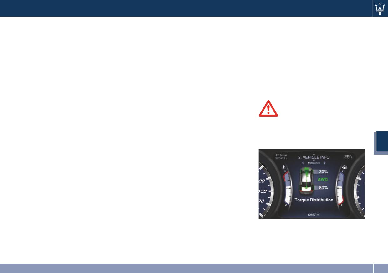
Driving
The D (Drive) position provides
the next step without pressing the
that wheel slip is unlikely to occur.
optimum driving characteristics under
unlock button on the lever will cause
When specific road and environmental
all normal operating conditions of the
the system to enter a temporary
conditions require increased levels of
vehicle.
function and enable the manual
road traction, the vehicle
shift mode. This range is indicated
automatically shifts into AWD mode.
• Vehicle stationary: switching from D
with the symbols “+/-” on the right
Drive mode, RWD, or AWD, is
(Drive) to R (Reverse) and/or to P
and left side of the “D” letter on the
displayed on the TFT display. Refer to
(Park) requires brake pedal and
gear range field of the display. The
paragraph “TFT Display” in chapter
unlock button pressed: reaching N
system will then switch back to
“Instrument Cluster” of section 4 for
(Neutral) starting from D (Drive) is
automatic mode according to time
further information.
allowed by only pressing the unlock
elapsed in “temporary” mode and
button on the shift lever.
driving conditions.
• To enable special operations while
At extremely cold temperatures (-23°F
WARNING!
the car is moving at a low speed,
/ -30°C or below), transmission may be
such as getting out of a marsh or
There may be a slight delay for AWD
affected by the low temperature of
snow, it is possible to run quickly
engagement after a wheel slip
the engine and transmission. Normal
from D (Drive) to R (Reverse), and
condition occurs.
operation will resume once the
vice versa, by pressing the reset
5
transmission temperature has risen to
button on the gear shift lever.
a normal level.
• Vehicle moving: switching to N
All-Wheel Drive (V6 Engine)
(Neutral) from D (Drive) requires the
unlock button on the shift lever
This vehicle is equipped with an active
pressed.
on-demand All-Wheel Drive (AWD)
system provides available optimum
• From D (Drive) selected mode it is
traction for a wide variety of road
always possible to switch to M
surface and driving conditions. The
(Manual), by pressing the M
system minimizes wheel slip by
(Manual) button: the Led indicator
automatically redirecting torque to
beside the button will light up; to
the front and rear wheels as necessary.
V6 Engine
return to D (Drive) position, the
To maximize fuel economy, the AWD
same action should be performed as
vehicle automatically defaults to
the LED will turn off.
Rear-Wheel Drive (RWD) when road
• When in D (Drive) mode, moving the
and environmental conditions are such
shift lever forward or backwards to
191
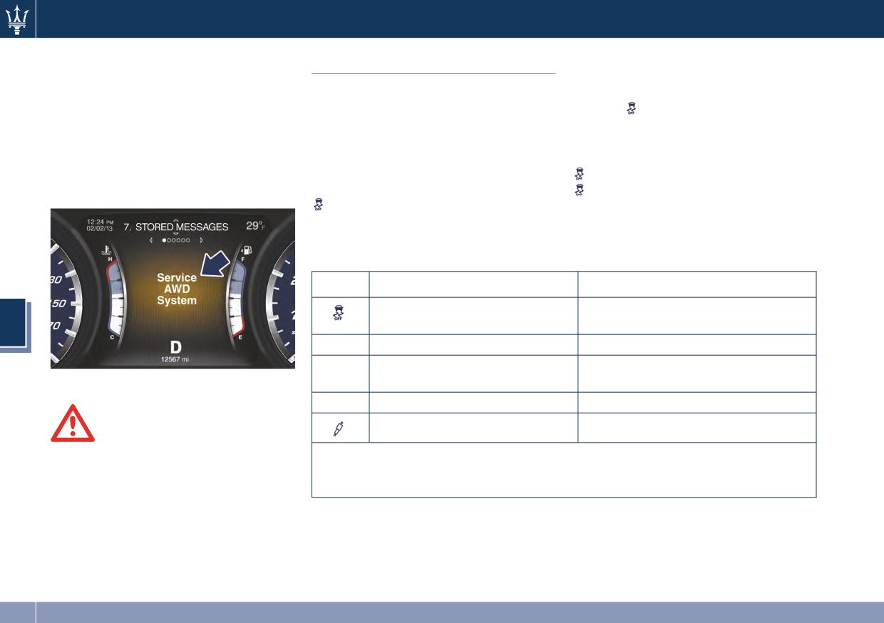
Driving
NOTE:
The tables below summarizes the
Drive Mode
adjustment of transmission and engine
If the “Service AWD System” warning
Keys (buttons) on the side of the shift
parameters according to set drive
message appears after engine start up,
lever only have two functions: OFF and
mode/s.
is the only mode that does
or during driving, it means that the
ON. The OFF state (button released) is
not depend on the activation or
AWD system is not functioning
the standard function mode. The ON
deactivation of the other modes. The
properly. If the warning message is
state is activated by pressing the
tables show the configurations with
often activated, it is recommended to
button, the dedicated LED will
button NOT pressed and the
go to the service.
illuminate. It is necessary to press the
button pressed.
button for at least 3 seconds.
The table shows the different drive
modes according to the state of the
keys.
Button
OFF - Button released
ON - Button pressed (LED ON)
Electronic Stability Control ESC
Electronic Stability Control ESC
activated
partially deactivated
5
M
Autoshift Mode (Auto)
Manual shift mode (Manual)
Increase Control Efficiency
Increase Control Efficiency
ICE
V6 Engine
mode OFF
mode ON (*)
SPORT
Normal drive mode (Normal)
Sportier drive mode (SPORT)
Soft suspensions setting (Soft)
Hard suspensions setting (Hard)
WARNING!
When “Service AWD System” is
(*) I C E (Increase Control and Efficiency) operates on engine supply in order to
activated driver should be aware of
reduce fuel consumption, exhausts, noisiness (efficiency) by dampen vehicle
different driving behavior and reduce
reactions (control). The current mode is also useful for low grip surfaces.
speed. The “Service AWD System” also
warns the driver not to drive into
cross country areas requiring AWD and
snow roads.
192
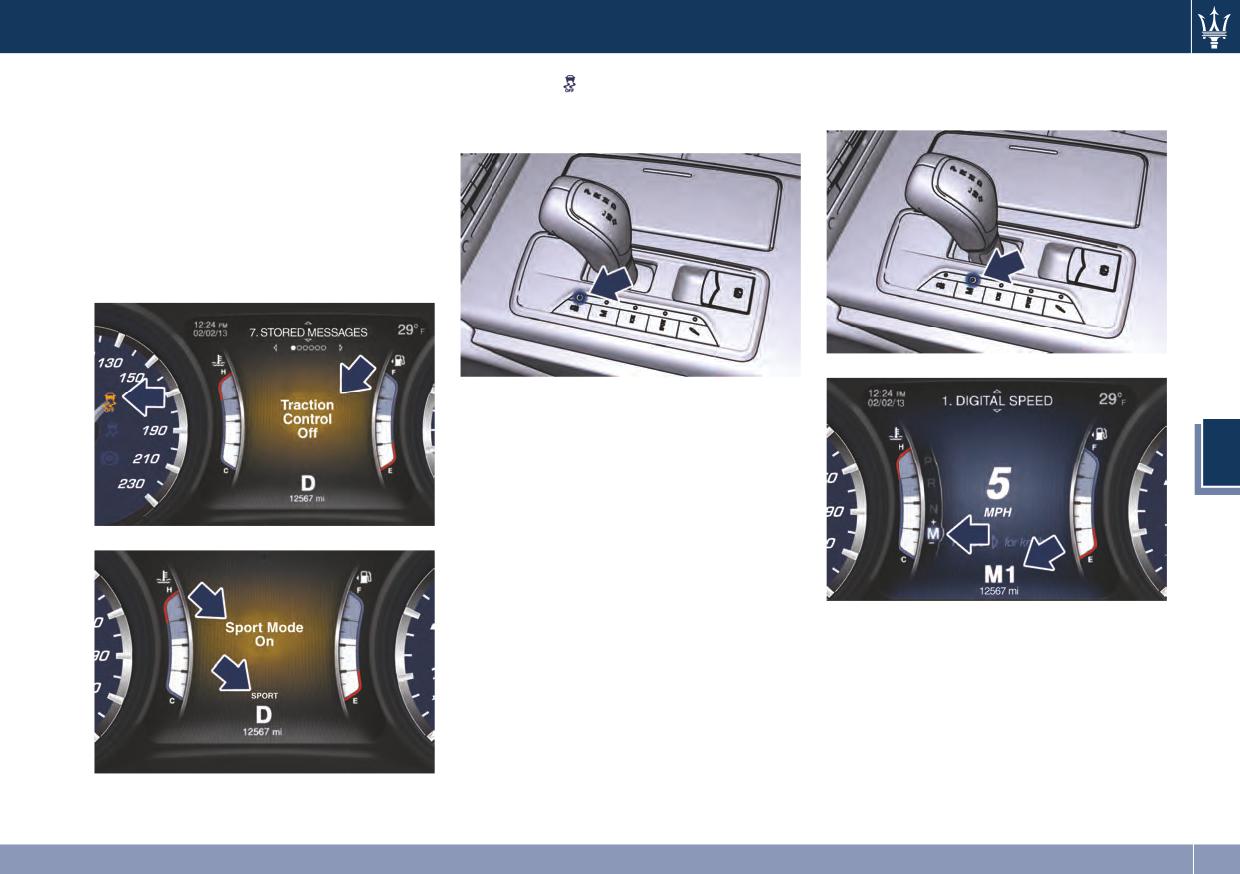
Driving
Activation/Deactivation of
To activate
button press the
gear is displayed on the instrument
corresponding button for at least 3
cluster beside “M”.
Drive Mode
seconds.
To insert a driving mode, briefly press
the corresponding button. The LED
beside the button will light along with
the indicator light on the display,
combined with a specific message for
5 seconds (see examples) or the
specific symbol of the set mode.
To disable the mode, press the button
again: the LED or symbol on the
cluster will turn off.
5
M (Manual) Drive Mode
In this mode, the transmission
interacts with the driver in order to
allow manual shift and ensure
increased control of the vehicle. The
current mode allows the gear system
to optimize the engine brake action,
Using the shift paddles behind the
remove undesired shifting into a
steering wheel (if present), the
higher and lower gears and improve
corresponding icon will display beside
the overall performance of the
the “M” indication and current shifted
vehicle.
gear.
This mode allows you to move the
Pull the right shift paddle (+) towards
shift lever step by step forward (-) or
the steering wheel and release it to
backward (+) without pressing the
enter the higher gear; do the same
lock button. The current transmission
195
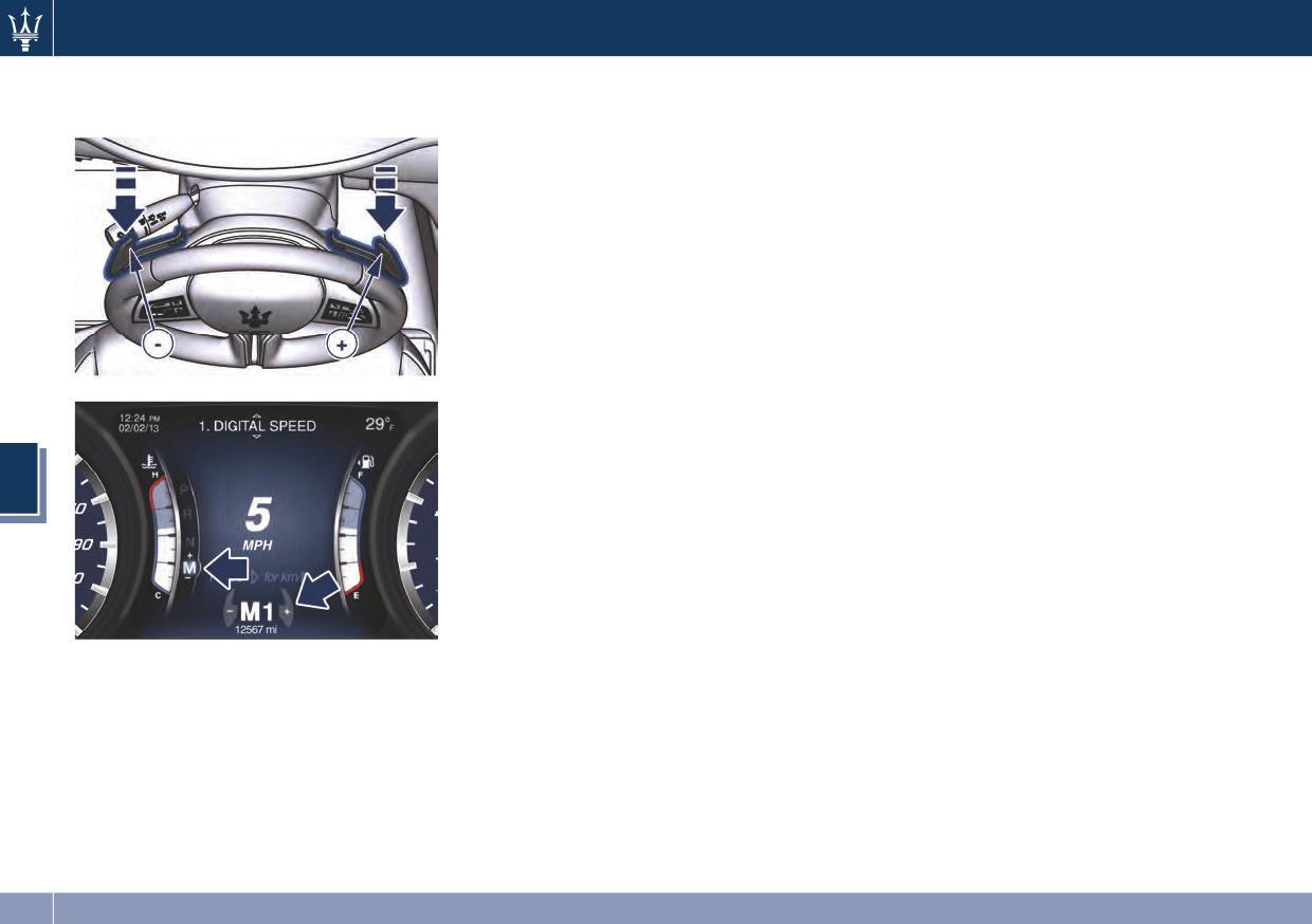
Driving
operation with the left shift paddle (-)
selected by the driver by using the
gear. If the vehicle speed is too low,
to enter the lower gear.
shift lever, or shift paddles on the
the system will ignore further
steering wheel (if present). The
upshifts. Avoid using speed control
transmission remains in the engaged
when the M (Manual) mode is
gear until the driver shifts into another
engaged.
higher or lower gear, except in the
Gear Shift Indicator Light
following cases.
In order to improve fuel economy, we
• Lack of accelerator pedal activity will
recommend that you shift gears when
cause the transmission to revert to
the system prompts you to do so. This
automatic operation. The
will help reduce fuel consumption
transmission will also upshift
without significantly affecting vehicle
automatically once maximum engine
performance.
speed is reached.
The indicator beside the displayed
• If in SPORT mode, the transmission
gear will light up just before reaching
will remain in the selected gear even
the required speed for gear change.
when maximum engine speed is
When the new gear is engaged, the
5
reached. The transmission will
indicator turns off. If the shift runs late
upshift only if enabled by the driver.
or is not performed at all, the indicator
Manual upshift or downshift will be
remains lit for a few seconds then
maintained as long as SPORT mode is
turns off. As soon as new conditions
selected, even by full stroke pedal
occur requiring further gear change,
press.
the indicator light will illuminate
• If in M (Manual) or in SPORT mode,
again.
Manual mode can be activated at any
the transmission will automatically
time, with no need to release the
downshift as the vehicle slows to halt
brake pedal.
(to prevent engine lugging) and the
Even if the release button is pressed
current gear will display on the
and gear is shifted in R (Reverse), P
instrument cluster. Shifting the gear
(Park) or N (Neutral), the selected
lever backward (+) or moving the
manual mode will be maintained.
right shift paddle (+) towards the
In Manual mode, the transmission will
steering wheel when stationary, will
shift up or down (+/-) if manually
cause the vehicle to start in second
196
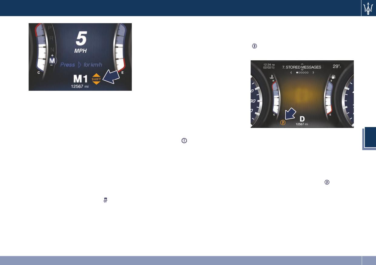
Driving
Transmission Malfunction and
Transmission Oil Over Temperature
If the transmission oil temperature
Overheating Conditions
exceeds the operating limit, the
Transmission Emergency Control
amber light illuminates on the
Transmission function is monitored
instrument cluster.
electronically to detect abnormal
conditions. If a condition is detected
that could result in transmission
damage, Transmission Limp Home
Mode is activated. In this situation, the
transmission may operate only in
NOTE:
certain gears, or may not shift at all.
The gearshift indicator will only work
Vehicle performance may be severely
when the transmission is set in M
degraded and the engine may stall. In
(Manual) mode.
some situations, the transmission
system may be able to re-engage or
I C E Mode excluding ESC
start the engine. The Malfunction
In this case, slow down until the
5
Indicator Light
may illuminate.
temperature returns to normal level
To release the vehicle in low grip
A message in the instrument cluster
(the light will turn off).
conditions (e.g.: snow, mud, sand, etc),
will inform the driver about the more
If this is not sufficient, we recommend
it is possible to shift the transmission
serious transmission conditions, and
you stop the vehicle, shift the lever to
feature in the specific driving mode as
indicate what actions may be
position P (Park) or N (Neutral) and
required for these situations, by
necessary.
keep the engine idle until the
pressing the I C E button and to
temperature warning light
turns
exclude completely the yaw and
off and the message disappears from
spinning control system, by pressing
the display. Resume driving without
the button for two seconds
demanding high engine performance.
197
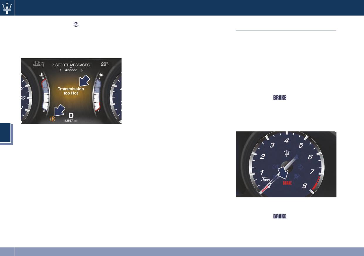
Driving
If the warning light
turns on again,
• Shift the transmission into D (Drive)
Parking Brake
it is advisable to stop the vehicle, turn
and then into the desired gear
off the engine and wait for the
range. If the problem is no longer
The vehicle is equipped with an
engine/transmission assembly to fully
detected, the transmission will return
electric automatic parking brake, also
cool down.
to normal operation.
called EPB (Electric Parking Brake).
It is automatically engaged when the
NOTE:
engine is turned off and disengaged
Even if the transmission can be reset,
with engine running and driver’s door
we recommend that you visit an
closed, while pressing the brake pedal
Authorized Maserati Dealer at your
and operating the shift lever.
earliest possible convenience, which
When the parking brake is applied, the
has diagnostic equipment to
warning light
lights up on the
determine if the problem could recur.
Rev Counter display and the related
message is displayed on the instrument
Transmission Manual Release of P
cluster for 5 seconds (see “Instrument
(Park) Position
Cluster” in section 4).
If the instrument cluster message
See chapter “Transmission Manual
5
indicates that the transmission may
Release of P (Park) Position” in section 6.
not re-engage after engine shutdown,
perform the following procedure
preferably at a Maserati Service
Center.
In the event of a momentary problem,
the transmission can be reset to regain
all forward gears by performing the
following steps.
• Stop the vehicle.
During engagement and
• Shift the transmission into P (Park), if
disengagement procedures, the
possible.
warning light
flashes until the
• Turn the engine off.
parking brake has reached its
• Wait approximately 30 seconds.
maximum activation force and is
• Restart the engine.
respectively fully released.
198
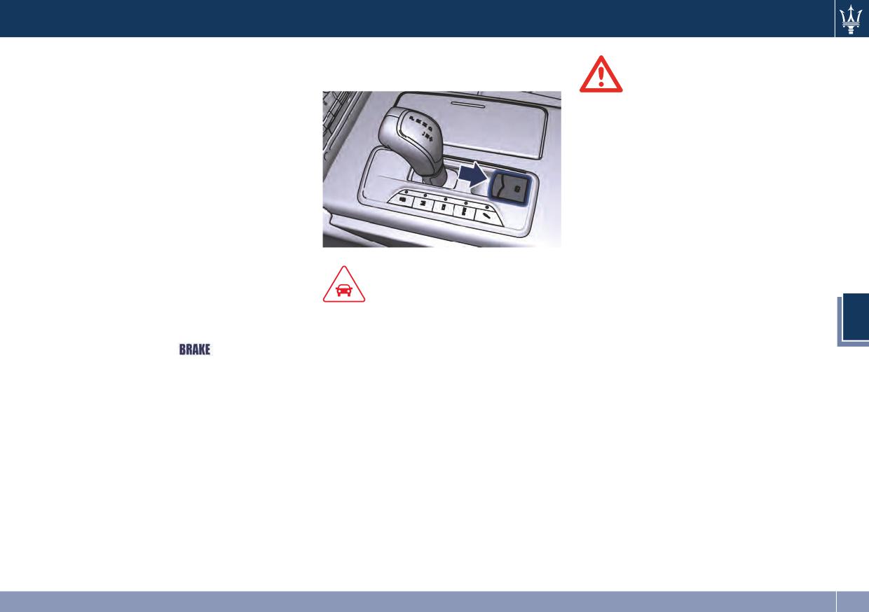
Driving
In the above mentioned conditions,
simply by pulling the lever upward
the automatic engagement function
within 3 minutes after turning off.
WARNING!
can be deactivated/activated by using
the command “Vehicle settings” on
• Always hold the brake pedal pressed
the main menu (refer to paragraph
during engagement or
“Deactivating Automatic Operation”
disengagement of the parking
in this chapter).
brake.
• The EPB command activation while
Manual Engagement/
running, generates a deceleration of
Disengagement
the vehicle with strong deceleration
The parking brake can also be
(Dynamic Braking). It is therefore
manually engaged or disengaged
recommended to use this feature
when the engine is running or the
only in case of emergency. The
ignition switch is in the RUN position,
stability of the car is guaranteed by
by pressing the brake pedal and
the action of the activated ESC
CAUTION!
raising the lever located behind the
system.
The main function of the EPB is to
shift lever.
5
allow safe parking of the vehicle,
When the parking brake is applied,
therefore it must only be applied
the warning light
lights up on
when the vehicle is already stationary.
the Rev Counter and the related
If the EPB is used while the vehicle is
message will be displayed for 5
moving and decelerating until a speed
seconds on the instrument cluster.
lower of 3 mph (5 km/h) and, in
If you attempt to engage/disengage
particular, until complete stop
the parking brake without having
(typically in a sudden brake), it is
pressed the brake pedal, a message
necessary to have the EPB system
will be displayed, warning you to
checked by the Authorized Maserati
proceed.
Dealer.
If the engine was turned off when the
automatic engagement device was
deactivated (see “Deactivating
Automatic Operation” in this chapter)
it is possible to shift the parking brake
199
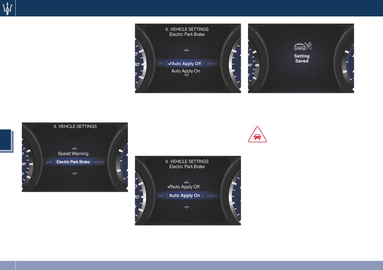
Driving
Deactivating Automatic
Operation
The automatic engagement function
can be deactivated/reactivated by
selecting the command “Vehicle
settings” on the main menu, the
command is reachable through the
switch on the right-side of the steering
wheel (refer to “Instrument Cluster” in
section 4.)
Scroll with the switch toward the
In order to resume the automatic
Press and release the switch toward
arrow ▲ or ▼ through the
operation follow the same procedures
the arrow ► to select “Electric Park
programmable options.
and selecting “Auto Apply Off”
Brake”.
Press and release the switch toward
option.
the arrow ► to set the selected
option. A check mark will remain next
CAUTION!
5
to the previously selected item until a
new selection is made.
• Under certain conditions when the
battery voltage is low, the electric
automatic parking brake system may
temporarily be deactivated for safety
reasons. Therefore, typically upon
starting the engine, when the
battery voltage drops, a message
Press and release the switch once
may temporarily be displayed,
again toward the arrow ► to visualize
indicating that automatic operation
the options connected to this function.
is temporarily disabled.
• Auto Apply On;
• In case of ripetitive requests to reset
• Auto Apply Off (default setting).
the EPB through the messages shown
“Setting Saved” Selection notification
on the TFT display, please contact the
appears as a popup for 2 seconds then
Authorized Maserati Dealer.
the display will show again the
modified function.
200
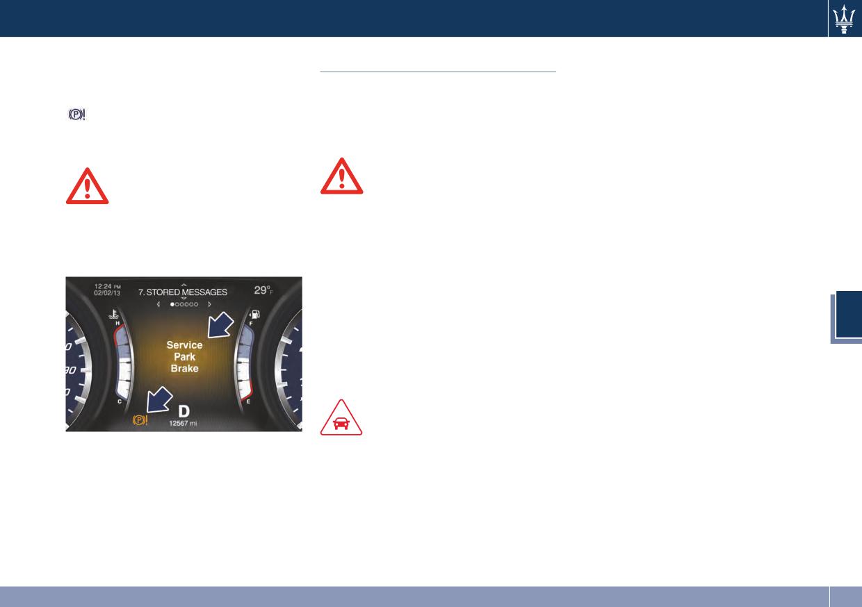
Driving
Failure Indication
Parking
When parking on hill roads, it is
important to turn the front wheels
In the event of electric parking brake
Before leaving the vehicle, make sure
toward the curb on a downhill grade
system failure, the warning light
that the parking brake is fully applied
and away from the curb on an uphill
on the display will light up and
and place the shift lever in the P (Park)
grade.
the related message will show for 5
position.
Apply the parking brake before
seconds.
placing the shift lever in P (Park),
otherwise the load on the
WARNING!
transmission locking mechanism may
WARNING!
make it difficult to move the shift
• Always check that the vehicle is
In the event of an EPB failure, take
lever out of P (Park).
locked before leaving it.
your vehicle to the nearest Authorized
In certain conditions, it is however
• Never leave children unattended in
Maserati Dealer as soon as possible.
advisable to disengage the parking
the vehicle.
brake manually and slightly apply the
• Do not park the vehicle on paper,
service brake for starting off. This is
grass, dry leaves or other flammable
advisable when there are obstacles
materials. They could catch fire if
very close to the vehicle in the
5
they come into contact with hot
direction in which you intend to move.
parts of the exhaust system.
• Do not leave the engine running
while the vehicle is unattended.
CAUTION!
Emergency Disengagement
When you need to park the vehicle on
In case of brake lock with complete
a steep slope, both with the engine on
electrical system failure, it is necessary
and off, it is recommended not only to
to release the brake manually (see the
engage the parking brake, but also to
complete procedure in “Emergency
shift the shift lever to P (Park) before
Release of the Parking Brake” chapter
leaving the vehicle.
in section 6).
201
Driving
“Drive Away Inhibit” strategy
In order to avoid a dangerous
condition due to leave the vehicle not
“braked” with running engine and
without driver on board, “Drive Away
Inhibit” strategy alerts the driver with
messages on the instrument cluster
display and sounding chimes, then put
the transmission in P (Park).
The table shows the vehicle condition
and the action that the system runs to
exit the dangerous condition.
Vehicle condition
Action of the driver
• Engine running and speed lower than
3 km/h (1.8 mph).
5
• Transmission in any position other P
The driver releases the brake pedal to
(Park).
get out of the vehicle.
The system put the
• Driver safety belt unlocked.
transmission in P
• Driver door opened.
(Park) position
• Brake pedal pressed.
Warnings
Warnings
• Slow continuous chime.
• Fast chime.
• “Vehicle not in Park” message on the
• “Secure vehicle to prevent
display.
movement" message on the display.
202
Driving
• These systems cannot prevent
tires and the road. Therefore, always
Brake and Stability
collisions, including those resulting
keep a safe distance from the vehicle
Control System
from excessive speed in turns,
in front of yours and reduce your
following another vehicle too
speed when entering a curve.
The vehicle is equipped with an
closely, or hydroplaning.
Electronic Stability Control System
(ESC), which helps to maintain
• The capabilities of a vehicle
NOTE:
directional control in the event of loss
equipped with these systems must
• When the vehicle's speed is higher
of traction of the tires. The system is
never be exploited in a reckless or
than 7 mph (11 km/h), you may also
able to detect potentially dangerous
dangerous manner that could
hear a slight clicking sound as well as
situations for the stability of the
jeopardize the driver’s and the
other motor noises. The system is
vehicle and automatically sets the
passenger’s safety or the safety of
performing a self-check cycle to
brakes on all four wheels in a
others.
ensure that the ABS is working
differentiated manner, in order to
properly.
provide a torque stabilizing of the
Anti-Lock Brake System (ABS)
• This self-check occurs each time the
vehicle. ESC includes following
vehicle is started and accelerated
The Anti-Lock Brake System (ABS)
subsystems:
past 7 mph (11 km/h).
provides increased vehicle stability and
5
• EBD (electronic brake force
brake performance under most
ABS is activated during braking under
distribution);
braking conditions. The system
certain road or stopping conditions.
• ABS (anti blocking system);
automatically “pumps” the brakes
ABS-inducing conditions can include
• TCS (traction control system);
during severe braking to prevent
ice, snow, gravel, bumps, railroad
• BAS (brake assist system);
wheel lock-up.
tracks, loose debris.
The Electronic Brake Force Distribution
You may also experience the following
• HSA (hill start assist).
(EBD) prevents the rear wheels from
when the brake system goes into Anti-
over-braking and provides greater
Lock:
control of available braking forces
WARNING!
• The ABS motor running (it may
applied to the rear axle.
continue to run for a short time
• These systems cannot prevent the
after the vehicle stops).
natural laws of physics from affecting
the vehicle, nor can it increase
• The clicking sound of solenoid
WARNING!
traction, braking or steering efficiency
valves.
The ABS helps prevent the wheels
beyond that afforded by the condition
• Brake pedal pulsations.
from locking, but it does not increase
of the vehicle brakes and tires.
the physical grip limits between the
203
Driving
• A slight drop or fall away of the
(aquaplaning), acceleration on slippery
Electronic Stability Control
brake pedal at the end of the stop.
snow-covered or frozen surfaces, etc.
(ESC)
These are all normal characteristics of
Activating under slip conditions
This system enhances directional
ABS functioning.
different control systems:
control and stability of the vehicle
• if slippage affects both drive wheels,
under various driving conditions. The
it reduces the power transmitted by
ESC corrects over steering and under
WARNING!
the engine;
steering of the vehicle by applying the
• The ABS contains sophisticated
• if slippage only affects one drive
brake to the appropriate wheel.
electronic equipment that may be
wheel, it brakes the slipping wheel
Engine power may also be reduced to
susceptible to interference caused by
automatically.
assist in counteracting the conditions
improperly installed or high output
of instability and maintain the right
radio transmitting equipment. This
Brake Assist System (BAS)
direction. The system is also able to
interference can cause possible loss
This system completes the ABS system
reduce the engine power.
of anti-lock braking capability.
by optimizing the vehicle braking
Through sensors fitted on the vehicle,
Installation of such equipment
capacity during emergency brake
the ESC system detects the driver’s
should be performed by qualified
maneuvers. The system detects an
chosen direction comparing it to the
5
Maserati personnel.
emergency braking situation by
one maintained while running. In case
• Pumping the Anti-Lock Brakes will
sensing the rate and amount of brake
of discrepancy between the required
diminish their effectiveness and may
application and then applies optimum
trajectory and the current one, the ESC
lead to a collision. Pumping brakes
pressure to the brakes in order to help
system brakes the appropriate wheel
makes the stopping distance longer.
reduce braking distances.
to counteract over or under steering.
Just press firmly on your brake pedal
The quick brake coupling is optimal for
when you need to slow down or
BAS performances. In order to fully
stop. Do not pump brakes.
exploit the system, apply continuous
brake pedal pressure during the entire
Traction Control System (TCS)
vehicle stop sequence. Do not reduce
brake pedal pressure earlier than
The current device is an integral part
required. Once the brake pedal is
of the ESC system. It operates
released, the BAS is deactivated.
automatically by reducing the power
transmitted by the engine in case of
slipping, loss of grip on wet floor
204
Driving
• Oversteer - when the vehicle is
NOTE:
brake pressure proportionally to the
turning more than appropriate for
amount of throttle/torque applied as
• When in “ESC off” mode, the TCS
the steering wheel position.
the vehicle starts to move in the
functionality of ESC is deactivated
• Understeer - when the vehicle is
(except for the limited slip feature
chosen direction.
turning less than appropriate for the
described in the TCS paragraph of
HSA Activation Criteria
steering wheel position.
this chapter). All other stability
The following criteria must be met in
The ESC system has two available
features of ESC function regularly.
order for HSA to activate:
operating modes:
• To improve the vehicle's traction
• vehicle is stationary.
ESC on
when driving with snow chains, or
• gear selection matches vehicle uphill
This is the normal ESC operating
when starting off in deep snow,
direction (i.e., vehicle facing uphill is
mode. At each start-up of the vehicle,
sand, or gravel, it may be desirable
in forward gear; vehicle backing
the ESC system is set in this mode and
to switch to the “ESC off” mode by
uphill is in reverse gear).
should be used for most driving
pressing the
switch and remain in
HSA will work in R (Reverse) and all
conditions. The ESC should only be
this operational mode no longer
forward gears when the activation
turned off for specific reasons as
than needed. Once the situation
criteria have been met.
pointed out in the following
requiring “ESC off” mode is
5
The system will not activate if the gear
paragraphs.
overcome, turn the ESC on again by
is placed in N (Neutral) or P (Park).
pressing the
switch. This may also
ESC off
be performed while in motion.
The “ESC off” mode is aimed for a
more spirited driving experience but
Hill Start Assist (HSA)
also purposeful for driving in deep
snow, sand, or gravel. The current
The HSA system is designed to assist
mode disables the TCS portion of the
the driver when starting a vehicle
ESC and raises the threshold for ESC
uphill. HSA will maintain the level of
activation, allowing higher wheel spin
brake pressure applied for a short
than normally granted by the ESC
period of time also after releasing the
system. The
switch is fitted beside
brake pedal.
the gear shift lever: to deactivate the
If the driver does not apply the
system see“Drive mode” in
throttle during this short period of
“Automatic Transmission” in this
time, the system will release brake
section.
pressure and the vehicle will start
sloping down. The system will release
205
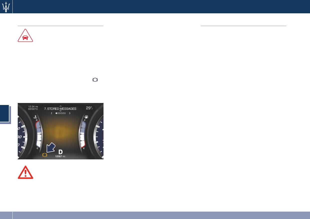
Driving
excessive lining wear, and possible
Using the Brakes
Use of the Engine
brake damage. In an emergency, full
braking capacity may be impaired.
Breaking-In
CAUTION!
Today's modern production methods
To obtain a good performance of
Brake pads and brake discs
are designed to provide extremely
brake pads and discs, avoid sudden
Wear on the brake pads and brake
precise construction and assembly of
braking during the first 190 mi
discs depends to a great extent on the
components. However, moving parts
(300 km).
driving style and the conditions of use
do undergo a settling process, basically
and therefore cannot be expressed in
in the first hours of vehicle operation.
The pad wear limit is indicated by the
actual miles driven on the road.
Avoid exceeding 5,000 rpm for the first
illumination of the warning light
,
The high-performance brake system is
620 mi trip (1,000 km).
on the instrument panel.
designed for optimal braking effect at
After starting the vehicle, do not
In this event, please contact an
all speeds and temperatures.
exceed 4,000 rpm until the engine has
Authorized Maserati Dealer.
Certain speeds, braking forces and
warmed up sufficiently (coolant
ambient conditions (e.g. temperature
temperature: 149-158°F / 65-70°C).
and humidity) can therefore cause the
Do not drive keeping at a constant
5
brakes to “squeal”.
high speed rate for a prolonged time.
While cruising, brief full-throttle
New brake pads and/or brake
acceleration within the limits of local
discs
traffic laws contributes to a good
New brake pads have to be “broken
break-in of the engine. Wide-open
in”, and therefore only attain optimal
throttle acceleration in low gear can
friction to the brake disc when the
be detrimental and should be avoided.
vehicle has covered several hundred
The engine oil installed in the engine
miles.
at the factory is a high-quality energy
During this first period, the slightly
conserving type lubricant. Oil changes
reduced braking ability must be
should be consistent with anticipated
WARNING!
compensated for by pressing the brake
climate conditions under which vehicle
Riding the brakes can lead to brake
pedal harder. This applies whenever
operations will occur. For the
failure and possibly an accident.
the brake pads and/or brake discs are
recommended viscosity and quality
Driving with your foot resting or
replaced.
grades, see “Maintenance Procedures”
riding on the brake pedal can result in
in section 7.
abnormally high brake temperatures,
206
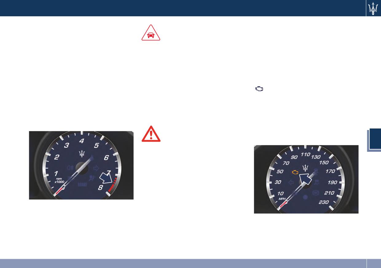
Driving
A new engine may consume some oil
transmission control systems. When
during its first few thousand miles of
these systems are operating properly,
CAUTION!
operation. This should be considered
your vehicle will provide excellent
as a normal part of the break-in
• Under normal conditions, all red
performance and fuel economy, as
period and not interpreted as an
warning lights on the instrument
well as engine emissions well within
indication of an engine malfunction.
cluster display should be off. When
current local regulations of various
they come on, this indicates a
countries.
While Driving
malfunction. Refer to “Instrument
If any of these systems require service,
Never travel with the Rev Counter
Cluster” in section 4.
the OBD II system will turn on the
indicator approaching the peak rpm,
malfunction indicator light (MIL).
• Continuing to drive when a red
not even downhill. When the Rev
It will also store diagnostic codes and
warning light is on could cause
Counter indicator is approaching the
other information to assist your
serious damage to the vehicle and
peak rpm (red colored zone), take
Maserati Service Center to service
affect its performance.
precautions to avoid exceeding that
your vehicle. Although the vehicle will
limit.
still be drivable and not need towing,
contact an Authorized Maserati
WARNING!
Dealer for service as soon as possible.
5
Do not travel downhill with the
engine off, as the power booster will
no longer function due to the vacuum
decrease. This can be realized, and if
done the system can become
ineffective. The power steering will
also lose its efficiency under these
conditions.
Ensure proper operation of different
devices checking their respective
On Board Diagnostic System
control warning lights.
Your vehicle is equipped with a
sophisticated onboard diagnostic
system called OBD II. This system
monitors the performance of the
emissions, engine, and automatic
207
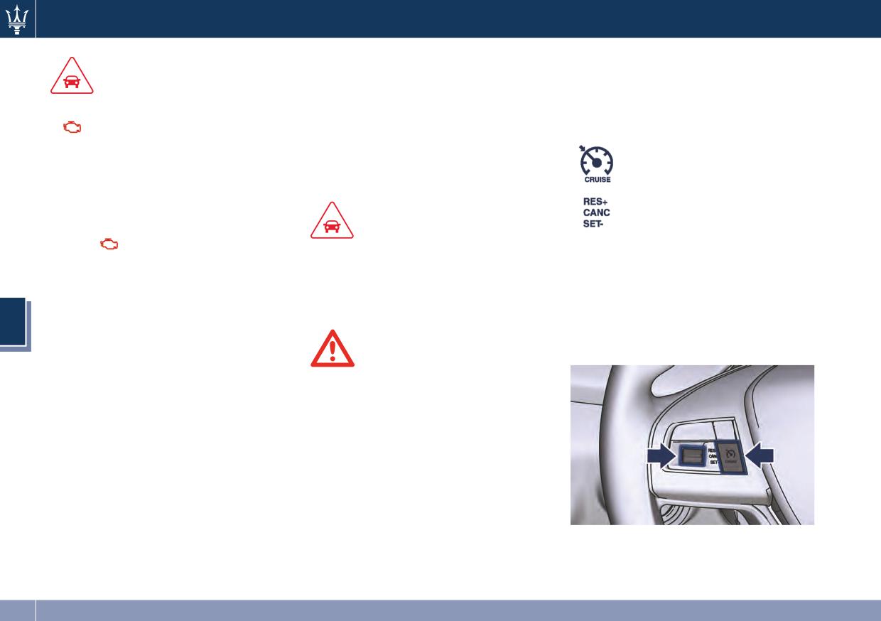
Driving
Electronic Cruise Control Controls
The electronic Cruise Control buttons
CAUTION!
The electronic speed regulator (Cruise
are located on the left side of the
Control) enables the driver to maintain
• Prolonged driving with the
steering wheel. Control buttons have
the desired vehicle speed without
malfunction indicator light (MIL)
following functions:
pressing the accelerator pedal,
on could cause further damage to
reducing driving fatigue on highways,
the emissions control system. It could
ON/OFF button:
especially long trips, as the set speed is
also affect fuel economy and
activation/deactivation;
automatically maintained.
drivability. The vehicle must be
multifunction control:
serviced before any emissions tests
• RES (+), pushed up:
can be performed.
CAUTION!
resume set speed (higher
• If the
malfunction indicator light
The device can only be switched on at
speed);
(MIL) is flashing while the engine is
speeds exceeding 19 mph (30 km/h)
• CANCEL, pushed: cancel
running, severe catalytic converter
and it switches off automatically when
set speed;
damage and power loss will soon
the brake pedal is pressed.
• SET (-), pushed down:
occur. Immediate service is required
setting speed (lower
5
at the Authorized Maserati Dealer.
speed).
• After the problem has been solved,
the Authorized Maserati Dealer
WARNING!
personnel will perform specific tests
The Cruise Control function must only
on the test bench for a complete
be activated when traffic and the
check of the system and, if necessary,
route allow maintaining a constant
also road tests, even on long
speed safely for a sufficiently long
distances.
distance.
208
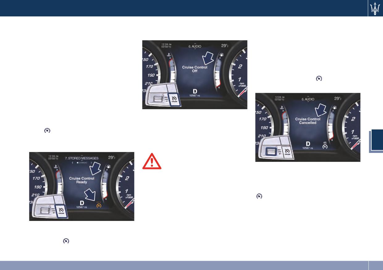
Driving
NOTE:
the display returns to the previous
Temporary Deactivation
setting.
In order to ensure proper operation,
A soft tap on the brake pedal, pushing
the electronic Cruise Control system
the CANCEL switch, or normal brake
has been designed to shut down if
pressure while slowing the vehicle will
multiple Cruise Control functions are
temporarily deactivate the Electronic
operated at the same time. If this
Speed Control without erasing the set
occurs, the electronic Cruise Control
speed memory, which will appear
system can be reactivated by pushing
above the white light
(in the
the electronic Cruise Control ON/OFF
example: 45 mph).
button and resetting the desired
vehicle set speed.
Activation
The system must be turned off when
Push the ON/OFF button. The amber
not in use.
light
in sector 13 of the instrument
Pressing the ON/OFF button or turning
cluster will illuminate and the related
the ignition switch OFF erases the set
5
message pops up for 5 seconds.
speed memory.
WARNING!
The related message will pop up for 5
Leaving the Electronic Speed Control
seconds on the instrument cluster and
system on when not in use is
the display will return to the previous
dangerous. You could accidentally set
setting, however, the white light
the system or cause it to go faster
will turn on as the Cruise Control is
than you want. Always leave the
still activated.
system OFF when you are not using it.
To turn the system off, push the
ON/OFF button a second time. The
amber light
will turn off and a new
message pops up for 5 seconds, then
209
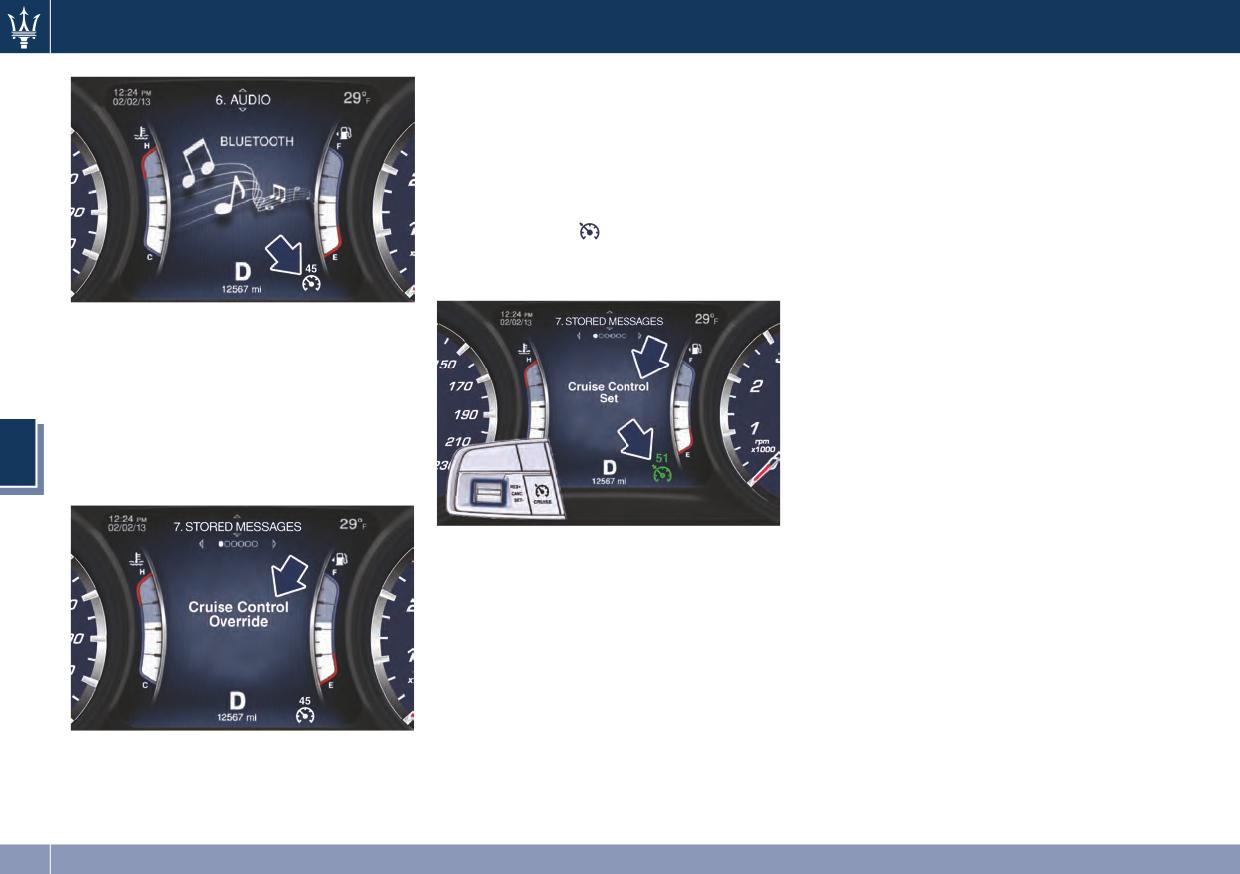
Driving
Setting Desired Speed
Resume Speed
Turn the electronic Cruise Control ON.
To resume a previously set speed, push
When the vehicle has reached the
the RES (+) switch upward and release.
desired speed (in the example:
Resume can be used at any speed
51 mph), push the switch downward
above 19 mph (30 km/h).
and release.
Changing Speed Setting
The green light
will illuminate and
the related message will pop up for 5
When the electronic Cruise Control is
seconds on the instrument cluster.
set, you can increase speed by pushing
the switch upward. Keeping the switch
If the driver presses the accelerator
pressed, the set speed will continue to
pedal while the Cruise Control is
increase until the switch is released,
active, such as to overtake another
then the new set speed will be
vehicle, and exceeds the speed limit,
maintained and memorized.
the system will temporarily deactivate
To decrease speed while the electronic
the speed regulator. A message pops
Cruise Control is activated, push the
5
up for 5 seconds on the instrument
switch downward. Keeping the switch
cluster to alert the driver.
pushed in the downward position, the
set speed will continue to decrease
until the switch is released. Release the
Release the accelerator and the vehicle
switch when the desired speed is
will operate at the selected speed.
reached, and the new set speed will be
maintained.
NOTE:
Pushing the switch upward or
The vehicle should be traveling at a
downward once will enable to increase
steady speed and on level ground
or decrease the set speed of 1.24 mph
before pushing the switch downward.
(2.0 km/h).
Each subsequent tap of the switch will
increase or decrease the speed of
When the accelerator pedal is
1.24 mph (2.0 km/h).
released, the vehicle will return to the
set speed.
210