Parker Variable Speed Drive AC30 series. User’s Manual (2017) - page 10
 

  Index      Manuals     Parker Variable Speed Drive AC30 series. User’s Manual (2017)


Search            copyright infringement  


Content      ..     8      9      10      11     ..


Parker Variable Speed Drive AC30 series. User’s Manual (2017) - page 10


Setup Wizard  

9-20


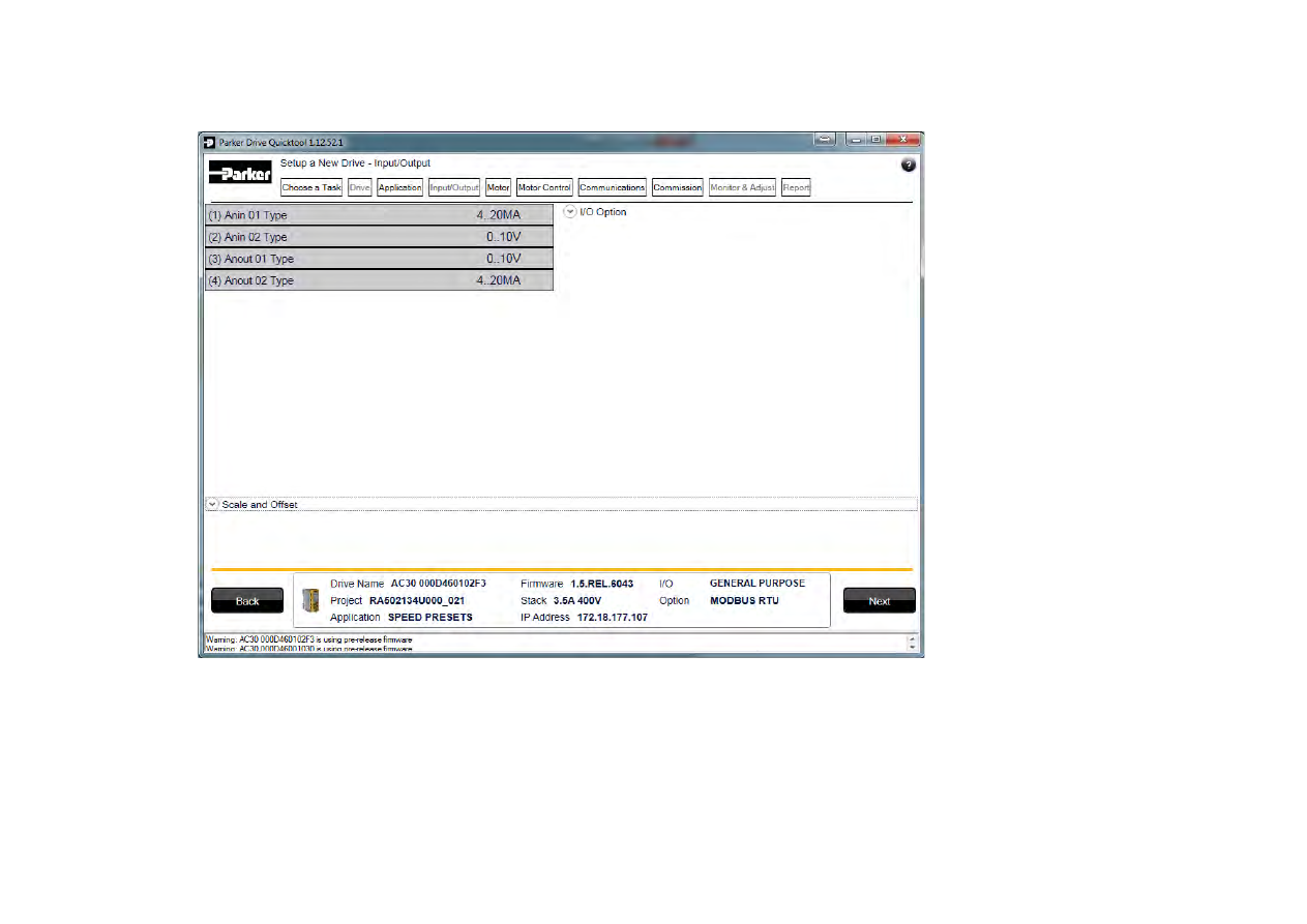
SETUP I/O 


Figure 9-7 Drive I/O setup 

On this screen the mode of the programmable I/O can be changed. If an I/O option card is fitted it can be configured in the “I/O Option” drop 
down. 
 

9-21 

Setup Wizard    

SELECT MOTOR 


Figure 9-8 Motor selection from database 

Motor data may either be selected form the built in motor database or entered by the engineer as a custom motor. 
The Motor page has two options at the top of the page that need to be selected. 


Figure 9-9 Motor data selection 

Setup Wizard  

9-22


“Database” is selected by default and the screen will show the motor database selector.  


Figure 9-10 Motor type selection 

“Induction Motor” is selected by default. This selection will filter the motor database to the selected type. It also displays only the appropriate 
“User” settings if a custom motor is required. 


Motor database 

At the left hand side is a list of manufacturers whose motors are in the database. Select the appropriate manufacturer from the list. If your motor’s 
manufacturer is not shown in the list then you will need to provide custom “User” data instead. 
 
Once the manufacturer is selected, the list of motor models will be displayed. The model list is sorted by the manufacturers part number. Select 
your motor from the list. The motors data and image will then be displayed so you can ensure you have the correct one selected. 


9-23 

Setup Wizard    


Figure 9-11 Custom Motor configuration 

Custom Motor 

Custom motor data is entered in this page. The page is split into two parts. On the top are “Basic” motor parameters and below are more 
advanced ones. Nominal defaults will have been set, depending on the size of inverter being configured. The Engineer should adjust these 
default values with data from the motor nameplate or technical specification. 


Setup Wizard  

9-24


SETUP THE DRIVE CONTROL 


Figure 9-12 Drive Control setup 

The “Control” page allows configuration of the Drive control. The basic control parameters are shown on the left hand side. Expand the 
“Advanced” dropdown to see more advanced parameters. The exact parameters show will depend on the motor type previously selected. 


9-25 

Setup Wizard    

SETUP COMMUNICATIONS 


Figure 9-13 Drive Communications setup 

The built in web browser can be enabled/disabled from this screen.  

If required, the built in Modbus can be setup from, the “Built in Modbus” dropdown. 

If an optional Fieldbus is fitted, it can be configured from the “Option Fieldbus” dropdown. 


Setup Wizard  

9-26


COMMISSION THE DRIVE  


Figure 9-14 Programming the Drive 

The “Commission” page is used to commission the Drive with the Selected macro and motor settings chosen during the Wizard. 

There are two steps that are performed to finalise the Commissioning of the Drive. 

1.  Enter the Project File name and the Drive’s name in the left of the screen. 

2.   “Program Drive”. This step writes your settings to the Drive and overwrites any existing configuration in the Drive. 

After these steps, the Drive is ready to use. 

9-27 

Setup Wizard    

MONITOR THE DRIVE 


Figure 9-15 Monitor the Drive and fine tune 

Setup Wizard  

9-28


Figure 9-16 Charting Drive Parameters 

Trips & Fault Finding  

10-1


Chapter 10: 

Trips & Fault Finding 

Trips and Fault Finding 

WHAT HAPPENS WHEN A TRIP OCCURS 

When a trip occurs, the drive’s power stage is immediately disabled causing the motor and load to coast to a stop. The trip is latched until action 
is taken to reset it. This ensures that trips due to transient conditions are captured and the drive is disabled, even when the original cause of the 
trip is no longer present. 

Keypad Indications 

If a trip condition is detected the activated alarm is displayed on the GKP display. 
 

RESETTING A TRIP CONDITION 

All trips must be reset before the drive can be re-enabled. A trip can only be reset once the trip condition is no longer active, i.e. a trip due to a 
heatsink over-temperature will not reset until the temperature is below the trip level. 
You can reset the trip as follows: 
 

1.  Press the 

 (STOP) key to reset the trip and clear the alarm from the display. 

2.  In remote terminal sequencing mode, create a 0 to 1 transition on the RESET TRIP bit, (bit 7), in the App Control Word parameter. 

3.  In remote communications sequencing mode, create a 0 to 1 transition on the RESET TRIP bit, (bit 7), in the Comms Control Word 

parameter. 

10-2 

Trips & Fault Finding  

USING THE KEYPAD TO MANAGE TRIPS 

Trip Messages 

 
If the drive trips, then the display immediately shows a message indicating the reason for the trip. The possible trip messages are given in the 
table below. 
 

ID 

Trip Name 

Possible Reason for Trip 

Criteria for Warning  

OVER VOLTAGE 

The drive internal dc link voltage is too high: 


The supply voltage is too high 


Trying to decelerate a large inertia load too quickly; DECEL TIME time too short 
The brake resistor is open circuit 
To help prevent this trip, enable the DC Link Volts Limit feature 

Internal dc link voltage has 
reached midway between the 
over voltage trip level and the 
dynamic braking resistor control 
voltage. 

UNDER VOLTAGE 

DC link low trip: 


Supply is too low/power down 

Internal dc link voltage has 
reached midway between the 
lowest expected instantaneous 
voltage and the under voltage 
trip level. 

OVER CURRENT 

The motor current being drawn from the drive is too high: 


Trying to accelerate a large inertia load too quickly; ACCEL TIME time too short 


Trying to decelerate a large inertia load too quickly; DECEL TIME time too short 


Application of shock load to motor 


Short circuit between motor phases 


Short circuit between motor phase and earth 


Motor output cables too long or too many parallel motors connected to the drive 


FIXED BOOST level set too high 

The over current trip makes up of 
a multiple-attempt strategy. 
The warning is triggered if two or 
more consecutive overcurrent 
events are encountered (whereas 
five consecutive events are 
required for a Trip to occur). 

STACK FAULT 

Stack self protection 


Instantaneous overcurrent detected by the power stack. Refer to OVERCURRENT 
in this table. 


Instantaneous over voltage event. Refer to OVER VOLTAGE in this table 

Not applicable. 

STACK OVER 
CURRENT 

The motor current exceeded the capabilities of the power stack. 


Instantaneous overcurrent detected by the power stack. Refer to OVERCURRENT 
in this table. 

Not applicable. 

CURRENT LIMIT 

V/Hz mode only: If the current exceeds 200% of stack rated current for a period 
of 1 second, the drive will trip. This is caused by shock loads 

Not applicable. 


Trips & Fault Finding  

10-3


ID 

Trip Name 

Possible Reason for Trip 

Criteria for Warning  

MOTOR STALL 

The motor has stalled (not rotating) Drive in current limit >200 seconds: 


Motor loading too great 


FIXED BOOST level set too high 

The stall condition has been 
detected for more than one tenth 
of the configured Stall Time. 

INVERSE TIME 

A prolonged overload condition, exceeding the Inverse Time allowance, has caused the 
trip:  


Remove the overload condition 

An overload condition has 
exceeded one half of the Inverse 
Time allowance. 

MOTOR I2T 

Only for PMAC Motor: A prolonged load condition, exceeding the motor rated 
current, has caused the trip. The estimated motor load has reached a value of 105% 

An overload condition has 
exceeded one half of the motor 
Inverse Time allowance. 

10 

LOW SPEED I 

The motor is drawing too much current (>100%) at zero output frequency: 


FIXED BOOST level set too high 

Not applicable. 

11 

HEATSINK 
OVERTEMP 

Drive heatsink temperature too high 


The ambient air temperature is too high 


Poor ventilation or spacing between drives 


Check heatsink fan is rotating 

The drive heatsink has exceeded 
the warning temperature level 
(which is approx. 10

°

C below the 

trip temperature). 

12 

INTERNAL 
OVERTEMP 

Processor temperature or ambient temperature within the power stage too high  


The ambient temperature in the drive is too high 

The drive processor temperature 
has exceeded the warning 
temperature level (which is 
approx. 10

°

C below the trip 

temperature). 

13 

MOTOR 
OVERTEMP 

The motor temperature is too high, (required IO Option card) 


Excessive load 


Motor voltage rating incorrect 


FIXED BOOST level set too high 


Prolonged operation of the motor at low speed without forced cooling 


Break in motor thermistor connection 

The motor has been over 
temperature for 7.5 seconds. 

14 

EXTERNAL TRIP 

The external (application) trip input is high: 


Refer to the application description to identify the source of the signal 

Not applicable. 

15 

BRAKE SHORT 
CCT 

External dynamic brake resistor has been overloaded: 


The external dynamic brake has developed a short circuit. 


Wiring fault 

Not applicable. 

10-4 

Trips & Fault Finding  

ID 

Trip Name 

Possible Reason for Trip 

Criteria for Warning  

16 

BRAKE RESISTOR 

External dynamic brake resistor has been overloaded: 


Trying to decelerate a large inertia too quickly or too often 

The power calculation for the 
external resistor has exceeded 
one half of the Brake Overrating 
allowance. 

17 

BRAKE SWITCH 

Internal dynamic braking switch has been overloaded: 


Trying to decelerate a large inertia too quickly or too often 

The power calculation for the 
internal dynamic braking switch 
has exceeded one half of the its 
overrating allowance. 

18 

LOCAL CONTROL 

Keypad has been disconnected from drive whilst drive is running in Local Control: 


GKP accidentally disconnected from drive 

Not applicable. 

19 

COMMS BREAK 

Lost option communications: 


A break in option communications has been detected.  Refer to option 
communications manual. 

Not applicable. 

20 

LINE CONTACTOR 

DC Link failed to reach the undervoltage trip level within the contactor feedback time. 


The Line contactor failed to connect. 


Missing 3-phase line supply 

Not applicable. 

21 

PHASE FAIL 


Indicates a missing input phase, for Frame K drives. 

Not applicable. 

22 

VDC RIPPLE 

The DC link ripple voltage is too high: 


Check for a missing input phase 


Repetitive start / stop or forward reverse action. 

The dc link ripple has exceeded 
75% of the trip level. 

23 

BASE MODBUS 
BREAK 

Lost Base Modbus communications: 


A break in the Base Modbus communications has been detected.  Refer to 
“Appendix A Modbus TCP”. 

Not applicable. 

24 

24V OVERLOAD 

24V rail is low 


Output overload due to excess current being drawn from the 24v terminal. 

Not applicable. 

25 

PMAC SPEED 
ERROR 

Only for PMAC motor : When using the Start feature in Sensorless Vector Control, the 
real speed hasn’t reached the speed setpoint after 5 seconds to move from open to 
closed loop control or to move from closed to open loop


Not applicable. 

26 

OVERSPEED 

Overspeed: 


>150% base speed when in Sensorless Vector mode


Not applicable. 


Trips & Fault Finding  

10-5


ID 

Trip Name 

Possible Reason for Trip 

Criteria for Warning  

27 

STO ACTIVE 

Attempt to run the motor with the Safe Torque Off active 


Check the STO wiring. It may be necessary to power the drive off and on to 
completely clear this event. 

Not applicable. 

28 

FEEDBACK 
MISSING 

The drive has been configured to run in Closed Loop Vector control mode with a Pulse 
Encoder IO Option, but the IO Option has not been correctly configured. 

The drive has been configured to run in Closed Loop Vector control mode with a 
System Board and/or a Pulse Encoder IO Option (using one of the 3 possible 
encoder inputs), but the system board or the IO option has not been declared as 
required.


Not applicable. 

29 

INTERNAL FAN 
FAIL 

An internal cooling fan has failed. This will reduce the lifetime of the power electronics. 


Return the power stack to a Parker Hannifin repair centre.


Not applicable. 

30 

CURRENT 
SENSOR 

Current feedback phase missing 


Check motor phase connections 

Not applicable. 

31 

POWER LOSS 
STOP 

A Power Loss Ride Through sequence has occurred and either 

1650 Pwrl Time Limit


has been exceeded or the motor speed has reached a zero speed during the sequence. 

Not applicable. 

32 

SPEED SENSOR 
FAULT 

Not applicable.


Encoder has failed whilst 
operating in vector control of 
induction motor. The drive 
switches to sensorless 
operation automatically (if 
this feature is enabled), and 
provides a warning to the 
user. 

33 

A1 

Application trip 1. The application trips are controlled by the Application_Trips block in 
the configuration. The text associated with each trip can be re-defined by the 
Application_Trips_Text block in the configuration. 

Application warning 1. 

34 

A2 

Application trip 2 

Application warning 2. 

35 

A3 

Application trip 3 

Application warning 3. 

36 

A4 

Application trip 4 

Application warning 4. 

37 

A5 

Application trip 5 

Application warning 5. 

38 

A6 

Application trip 6 

Application warning 6. 

39 

A7 

Application trip 7 

Application warning 7. 

10-6 

Trips & Fault Finding  

ID 

Trip Name 

Possible Reason for Trip 

Criteria for Warning  

40 

A8 

Application trip 8 

Application warning 8. 

41 

SPEED ERROR 
FAULT 

Difference between actual motor speed and the speed setpoint is greater than a 
threshold for a  period of time.  

Difference between actual motor 
speed and the speed setpoint has 
been greater than the trip 
threshold for more than half the 
trip delay time.


42 

PEER TO PEER 
OVERRUN 

Configuration error on Master and/or Slave(s) side 

PTP or Peer to Peer are OFF on one drive 

Destination IP or Destination Port incompatible between Master and Slave(s) 

Peer to Peer is not useable 

Multiple delayed Peer To 
Peer messages have 
occurred.  This may cause 
incorrect phase alignment if 
phase control is being used.  

43 

PHASE CONFIG 

Something is wrong in the phase configuration : one or more of the encoders set up 
for speed control, master and/or slave are wrongly declared. See Phase Ctrl Config : 
Error Number for a detailed description of the error 
(Only applicable if phase control is enabled)


Not applicable

44 

ETHERNET IP 
BREAK 

Lost Base EtherNet IP communications: 

A break in the Base EtherNet IP communications has been detected.  Refer to 
“Appendix A EtherNet IP Adapter”. 

Not applicable. 

45 

RESOLVER 
ERROR 

An error has been detected on the resolver signals 
Error type is available by looking at 

1820 Resolver Trip Type


Not applicable 

46 

PMAC ALIGN 
ERROR 

If 

1796 Alignment on Power On 

has been set to TRUE, the drive should run a 

successful Pos Alignment sequence, at power up before being run safely. 
or 
Something wrong occurred during the last Pos Alignment sequence. 
Error type is available by looking at 

1807 Alignment error


Not applicable 


Trips & Fault Finding  

10-7


HEXADECIMAL REPRESENTATION OF TRIPS 

 
Each trip has a unique, eight-digit hexadecimal number as shown in the tables below. This number is referred to as the trip mask. The trip masks 
are used in the Enable, Active and Warnings parameters in the Trips module. 


ID


Trip Name 


Mask 

User 

Disable 

OVER VOLTAGE 

00000001 


UNDER VOLTAGE 

00000002 


OVER CURRENT 

00000004 


STACK FAULT 

00000008 


STACK OVER CURRENT 

00000010 


CURRENT LIMIT 

00000020 


MOTOR STALL 

00000040 


INVERSE TIME 

00000080 


MOTOR I2T 

00000100 


10 

LOW SPEED I 

00000200 


11 

HEATSINK OVERTEMP 

00000400 


12 

AMBIENT OVERTEMP 

00000800 


13 

MOTOR OVERTEMP 

00001000 


14 

EXTERNAL TRIP 

00002000 


15 

BRAKE SHORT CCT 

00004000 


16 

BRAKE RESISTOR 

00008000 


17 

BRAKE SWITCH 

00010000 


18 

LOCAL CONTROL 

00020000 


19 

COMMS BREAK 

00040000 


20 

LINE CONTACTOR 

00080000 


21 

PHASE FAIL 

00100000 


22 

VDC RIPPLE 

00200000 


23 

BASE MODBUS BREAK 

00400000 


ID


Trip Name 


Mask 

User 

Disable 

24 

24V OVERLOAD 

00800000 


25 

PMAC SPEED ERROR 

01000000 


26 

OVERSPEED 

02000000 


27 

SAFE TORQUE OFF 

04000000 


28 

FEEDBACK MISSING 

08000000 


31 

POWER LOSS STOP 

40000000 


32 

SPEED SENSOR FAULT 

80000000 


33 

A1 

00000001* 


34 

A2 

00000002* 


35 

A3 

00000004* 


36 

A4 

00000008* 


37 

A5 

00000010* 


38 

A6 

00000020* 


39 

A7 

00000040* 


40 

A8 

00000080* 


41 

SPEED ERROR FAULT 

00000100* 


42 

PEER TO PEER OVERRUN  00000200* 


43 

PHASE CONFIG 

00000400* 


44 

ETHERNET IP BREAK 

00000800* 


45 

RESOLVER ERROR 

00001000* 


46 

PMAC ALIGN ERROR 

00002000* 


* These masks apply to parameter words “33 – 64” 


Content      ..     8      9      10      11     ..