Parker 590+ series Frame 1, 2, 3, 4, 5, 6 & H. Product Manual (2012) - page 31
Appendix E Technical Specifications
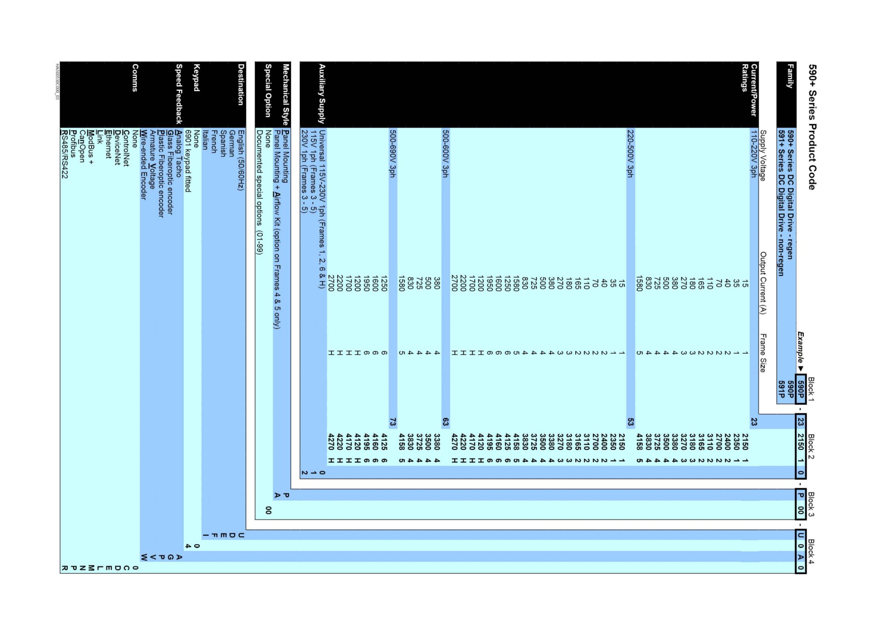
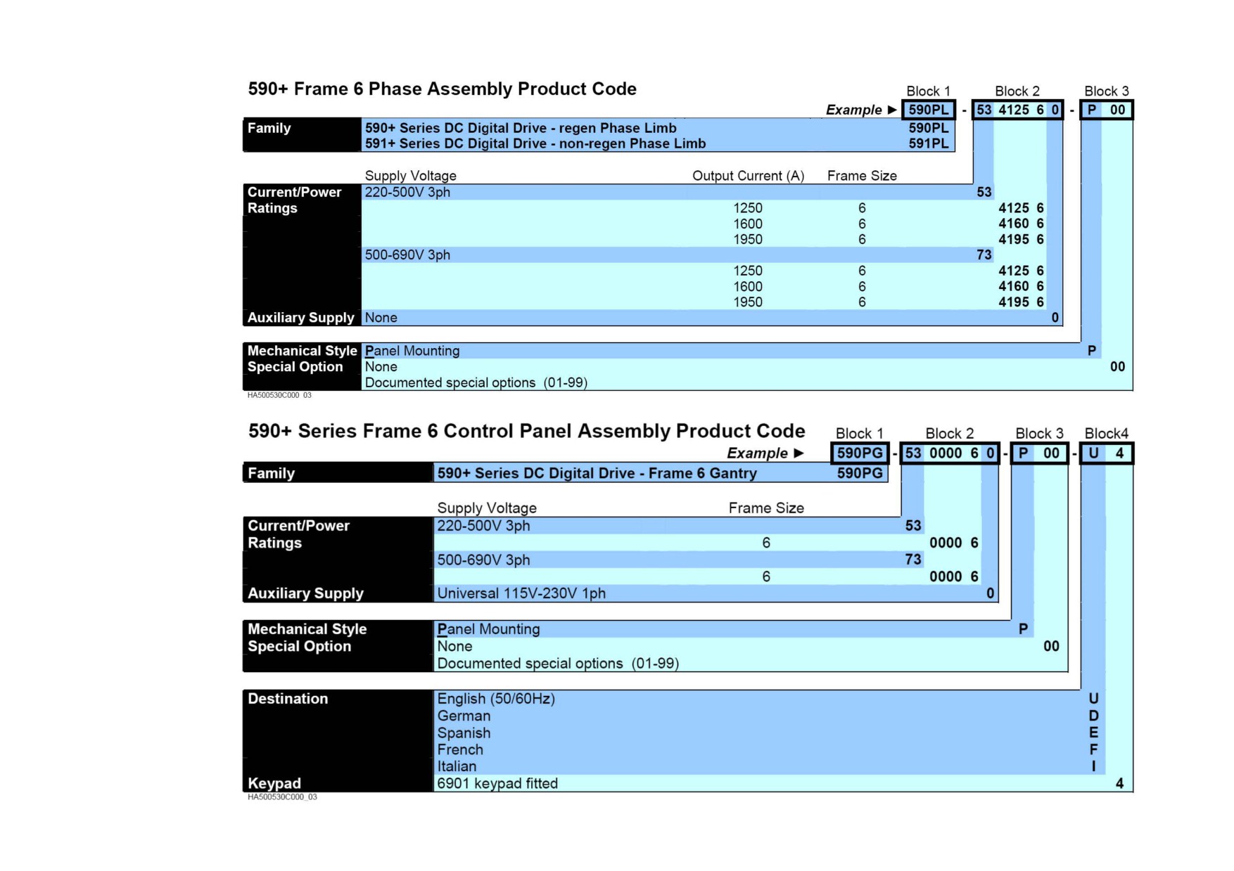
Understanding the Product Code
Technical Specifications
• Model Number
Technical Specifications E-1
Understanding the Product Code
Model Number
The unit is fully identified using an alphanumeric code which records how the Drive was calibrated, its various settings when despatched from the
factory, and the country of origin.
The Product Code appears as the “Model No”. Each block of the Product Code is identified as over.
E-2 Technical Specifications
Technical Specifications E-3
E-4 Technical Specifications
Door Assembly Product Code
The door assembly is identified separately. The Product Code appears on a label displayed under the terminal cover.
Block No.
Variable
Description
1
XXXXX
Generic product
590PD :
Fits Frame 4 and 5 units
590PXD :
Fits Frame 3, 6 & H units
2
XXXX
4 digits describing the mechanical package including livery and mechanical package style:
First two digits (on the left) Livery
00
Standard Parker SSD Drives Livery
05
Distributor Livery
01-04 and 06-99
Defined customer liveries TBA
Third digit
Mechanical Package Style
1
Standard
Fourth digit
Keypad
0
No keypad
1
Built-in keypad
3
XX
Two characters specifying the user interface language:
UK = English
FR = French
GR = German (refer to Customer Services)
SP = Spanish (refer to Customer Services)
IT = Italian (refer to Customer Services)
4
XXX
Up to three characters specifying engineering special options:
0 = No special option
Technical Specifications E-5
Technical Specifications
Environmental Details
Operating Temperature
Frame 1 :
0°C to +45°C
Frame 4 :
0°C to +40°C
Frame H :
0°C to +40°C
Frame 2 :
0°C to +45°C
Frame 5 :
0°C to +40°C
Frame 3 :
0°C to +35°C
Frame 6 :
0°C to +40°C
Operating temperature is defined as the ambient temperature to the immediate surround of the Drive, when the Drive and other
equipment adjacent to it is operating at worst case conditions.
Output current values should be derated at 1% per degree Centigrade above rated temperature up to a maximum of 55°C.
Storage Temperature
-25°C to +55°C
Shipping Temperature
-25°C to +70 °C
Product Enclosure Rating
IP00 (Europe)
[Frame 1 unit is IP20]
UL Open Type (North America/Canada)
If the product enclosure is totally enclosed, the exposed metal surface dissipates approximately 50W/m² for a 10°C temperature
rise of internal air above ambient.
Vibration
Test Fc of EN60068-2-6
10Hz<=f<=57Hz sinusoidal 0.075mm amplitude
57Hz<=f<=150Hz sinusoidal 1g
10 sweep cycles per axis on each of three mutually perpendicular axis
Altitude
If >500 metres (1650 feet) above sea level, derate Motor Power rating by 1% per 200 metres (660 feet) to a maximum of 2,000
metres (6,561 feet)
Humidity
Maximum 85% relative humidity at 40°C non-condensing
Atmosphere
Non flammable, non corrosive and dust free
Climatic Conditions
Class 3k3, as defined by EN60721-3-3 (1995)
Safety
Europe
EN61800-5 : 2003, when fitted inside a cubicle
North America/Canada
UL508C
Overvoltage Category
Overvoltage Category III (3-phase supply), Overvoltage Category II (auxiliary supply)
Pollution Degree
Pollution Degree 2
E-6 Technical Specifications
Electrical Ratings - Power Circuit
Refer to Chapter 3: “Earth Fault Monitoring Systems” for circuit breaker details.
Motor HP ratings as NEC Table 430-147: “Full Load Current in Amperes, DC Motors”’
Output Current @
Output Current @ 100%
Power @ 500V dc
Motor HP @ 500V
Field Current
Total Losses @ Full
Symmetrical Fault
150% and 200% *
Continuous *
dc
Load
Current rms
(kW)
(HP)
(A)
(W)
(kA)
(A)
(A)
Frame 1
15
15
7
7.5
4
57
5
35
35
15
20
4
117
5
Frame 2
40
40
18
25
10
132
10
70
70
30
40
10
234
10
110
110
50
60
10
354
10
165
165
75
100
10
519
10
Frame 3
180
180
80
50 ♦
10
570
10
270
270
120
150
10
840
10
Frame 4
380
420
150
200 Η
30
1230
18
500
550
225
300 Η
30
1590
18
725
800
327
400 Η
30
2265
30
830
910
335
500 Η
30
2580
30
Frame 5
1580
1740
650
900 Η
30
4890
85
Frame 6
1250
1350
600
800
60
4600
100
1600
1750
750
1000
60
5000
100
1950 #
2150
900
1200
60
6000
100
Technical Specifications E-7
Electrical Ratings - Power Circuit
Refer to Chapter 3: “Earth Fault Monitoring Systems” for circuit breaker details.
Motor HP ratings as NEC Table 430-147: “Full Load Current in Amperes, DC Motors”’
Output Current @
Output Current @ 100%
Power @ 500V dc
Motor HP @ 500V
Field Current
Total Losses @ Full
Symmetrical Fault
150% and 200% *
Continuous *
dc
Load
Current rms
(A)
(A)
(kW)
(HP)
(A)
(W)
(kA)
Frame H
1050
1200
550
700 †
60
3780
100
1450
1700
750
1000 †
60
5280
100
2000
2200
1000
1250 †
60
6780
100
2400
2700
1200
1500 †
60
8280
100
Output current values should be derated at 1% per degree Centigrade above rated temperature up to a maximum of 55°C.
Output current values should be derated at an altitude of 500 metres above sea level at a rate of 1% per 200 metres to a maximum of 5000 metres.
* The output current figures are given at 100% Continuous (no overload), and with overloads of 150% for 30 seconds or 200% for 10 seconds.
♦ Rated armature voltage : 240V dc
Η These products are suitable for supplies up to 600V ac and armature voltages of 700V dc, hence output power ratings can be increased by up to 140%
# Derated to 1850/1950 on HV assemblies
† These products are suitable for supplies up to 690V ac and armature voltages of 750V dc, hence output power ratings can be increased by up to 150%
EMC Compliance
All models
European Community Directive 2004/108/EC
All models
EN61800-3 (2004) Table 17 : conducted emissions when installed in accordance with the instructions in Chapter 3.
Refer to "Mounting the Drive".
EN61800-3 (2004) Immunity requirements:
Maximum controlled speed (with feedback option) deviation = ±1%
Maximum controlled armature current deviation = ±1%
Maximum controlled field current deviation = ±10%
Maximum line impedance 3% for compliance (defined as percentage drop in line-to-neutral voltage when
rated dc current flows in armature output)
EN61800-3 (2004) Table 18 Radiated emissions
If fitted with specified external filters
EN61800-3 (2004) restricted distribution: conducted emissions
(except Frames 6 & H)
E-8 Technical Specifications
Power Supply Details
3-Phase
LV Build
All Frames
110-220V ac ±10%, 50/60Hz ± 5%, line-to-line, ground referenced (TN) and non-ground referenced (IT)
Supply
MV Build(standard)
All Frames
220-500V ac ±10%, 50/60Hz ± 5%, line-to-line, ground referenced (TN) and non-ground referenced (IT)
HV Build
Frame 4
500-600V ac ±10%, 50/60Hz ± 5%, line-to-line, ground referenced (TN) and non-ground referenced (IT)
Frame 5
Frame 6 & H
500-690V ac ±10%, 50/60Hz ± 5%, line-to-line, ground referenced (TN) and non-ground referenced (IT)
Supply Current
(0.9 x Idc) Amps ac rms
Field Supply Current
(1 x Idc) Amps ac rms (build related)
Field Supply Voltage
Build-related
3 Phase Input
3-phase rotation insensitive, no adjustment necessary for frequency change
Auxiliary Power Supply Details
Auxiliary Supply
110-230V ±10%, 50-60Hz ±10%, single phase, Overvoltage Category II
Where auxiliary cooling fans are used, then the supply is set by the requirement for the fan, i.e. 115V ±10% or 230V ±10%. Refer to
Model Number, page E-E-1.
3A ac rms maximum. Nominal current used for power supplies:
0.5A at 115V ac, 0.25A at 230V ac
Auxiliary Supply Current
Fan current for integral fans: refer to Cooling Fans, page E-32. The remainder is available for driving the AC Contactor
Frame 6: Total of 3A ac maximum, 250W.
Contactor Output
3A maximum at the auxiliary voltage
Technical Specifications E-9
AC Line Choke (Frames 1-5)
To correctly isolate the DC590+ drive from the ac power system, and to protect other equipment from transients on the power system, always use the
recommended external ac line choke (or alternatively a transformer may achieve the necessary isolation).
Note that the Frame 5 requires two ac line chokes (one in front of each of the paralleled drives). This provides isolating impedance between the
drive and its ac power source. It also provides the necessary impedance between the paralleled drives, forcing them to share the total motor current
evenly. The Frame 5 drive must still use two ac line chokes when a transformer is used for isolation, however, the chokes can be of a much lower
inductance, typically 3-5 µH.
Drives below 100A Armature Current rating cannot achieve conformance with EN61800-3 Table 17 using only a 50μH line choke. Capacitors must
be fitted between phase and earth to achieve conformance. Refer to Chapter 3: "Installing the Drive" - Filtering.
Armature Current Rating (A)
AC Rating (A)
Inductance (μH)
Parker SSD Drives Part No.
500Vac
600Vac
500Vac
600Vac
For use without filters (use with capacitors for armature currents <100A, refer to Chapter 3: "AC Line Choke")
Frame 1
15
13.5
50 μH
-
CO466448U015
-
35
36
50 μH
-
CO466448U040
-
Frame 2
40
36
50 μH
-
CO466448U040
-
70
63
50 μH
-
CO466448U070
-
110
100
50 μH
-
CO466448U110
-
165
148.5
50 μH
-
CO466448U165
-
Frame 3
180
162
50 μH
-
CO055255
-
270
243
50 μH
-
CO057960
-
AC Line Chokes @ 2% line impedance for conformance with EN61800-3 (2004) Table 14 Category C2 when used with specified filters.
Frame 1
15
13.5
1130 μH
-
CO466449U015
-
35
36
424 μH
-
CO466449U040
-
Frame 2
40
36
424 μH
-
CO466449U040
-
70
63
242 μH
-
CO466449U070
-
110
100
154 μH
-
CO466449U110
-
165
148.5
113 μH
-
CO466449U165
-
Frame 3
180
162
113 μH
-
CO463039
-
270
243
50 μH
-
CO057960
-
E-10 Technical Specifications
AC Line Choke (Frames 1-5)
To correctly isolate the DC590+ drive from the ac power system, and to protect other equipment from transients on the power system, always use the
recommended external ac line choke (or alternatively a transformer may achieve the necessary isolation).
Note that the Frame 5 requires two ac line chokes (one in front of each of the paralleled drives). This provides isolating impedance between the
drive and its ac power source. It also provides the necessary impedance between the paralleled drives, forcing them to share the total motor current
evenly. The Frame 5 drive must still use two ac line chokes when a transformer is used for isolation, however, the chokes can be of a much lower
inductance, typically 3-5 µH.
Drives below 100A Armature Current rating cannot achieve conformance with EN61800-3 Table 17 using only a 50μH line choke. Capacitors must
be fitted between phase and earth to achieve conformance. Refer to Chapter 3: "Installing the Drive" - Filtering.
Armature Current Rating (A)
AC Rating (A)
Inductance (μH)
Parker SSD Drives Part No.
500Vac
600Vac
500Vac
600Vac
AC Line Chokes @ 1% line impedance for conformance with EN618003 (2004) Table 14 Category C2 when used with specified filters.
Frame 4
380
342
-
30 μH
-
CO466709U038
500
450
-
25 μH
-
CO466709U050
725
653
-
20 μH
-
CO466709U073
830
747
-
15 μH
-
CO466709U083
Frame 5 (2 chokes required)
0831-1200
747
-
20 μH
-
CO466709U073
0831-1200
747
-
5 μH
-
CO466709U120
(use with transformer only)
1201-1580
747
-
15 μH
-
CO466709U083
1201-1580
747
-
5 μH
-
CO466709U160
(use with transformer only)
Technical Specifications E-11
AC Line Choke (Frames 6 & H)
Always use the recommended external AC Line Choke.
DC Rating
AC Current
Inductance
Parker SSD Drives Part No.
AC Line Choke @ 2% line impedance.
Frame 6
1250
500V
1080A
15μH
CO466250U012
690V
1080A
20μH
CO466251U012
1600
500V
1620A
10μH
CO466250U017
690V
1620A
15μH
CO466251U017
1950
500V
1980A
10μH
CO466250U022
690V
1980A
15μH
CO466251U022
Frame H
1200
LV
1080A
15μH
CO466250U012
HV
1080A
20μH
CO466251U012
1700
LV
1620A
10μH
CO466250U017
HV
1620A
15μH
CO466251U017
2200
LV
1980A
10μH
CO466250U022
HV
1980A
15μH
CO466251U022
2700
LV
2520A
7.5μH
CO466250U027
HV
2520A
10μH
CO466251U027
E-12 Technical Specifications
External AC Supply (RFI) Filters
Filters must only be fitted on the mains side of the contactor.
AC supply filter part numbers for conformance with EN61800-3 (2004) Table 14 Category C2.
Armature Current Rating (A)
Total Filter Watt Loss (W)
Parker SSD Drives Filter Part No.
Frame 1
15
11
1 off CO467844U015
35
16
1 off CO467844U040
Frame 2
40
16
1 off CO467844U040
70
16
1 off CO467844U070
110
18
1 off CO467844U110
165
25
1 off CO467844U165
Frame 3
180
158
1 off CO467844U180
270
50
1 off CO467843U340
Frame 4
380
100
2 off CO467843U340
500
100
2 off CO467843U340
725
150
3 off CO467843U340
830
150
3 off CO467843U340
Frame 5
1580 (please contact Parker SSD Drives)
Frame 6
1350-2150 (please contact Parker SSD Drives)
Frame H
1200-2700 (please contact Parker SSD Drives)
Technical Specifications E-13
External Power Semiconductor Protection Fuses (Frames 1-5)
For fuses where compliance to UL Standards are required, refer to Appendix B: “Certification” - Branch Circuit/Short Circuit Protection
Requirements.
Controller Rating
Line Fuse Rating
Parker SSD Drives Part No.
Fuse I²t @ 600V
Thyristor I²t
(A)
(A)
(kA²s)
(kA²s)
Frame 1
15
25
CS470445U025
0.31
0.72
35
40
CH570044
0.46
0.72
Frame 2
40
40
CH570044
0.46
1.15
70
80
CH570084
2.55
8
110
160
CH580164
7.5
15
165
200
CH580025
15
19.1
Frame 3
180
200
CH580025
15
19.1
270
500
CH590554
135 (*102)
125
Frame 4
380
550
CH590554
135
240
500
700
CH590075
300
306
725
900
CH590095
670
781
830
1000
CH590016
945
1125
Frame 5
1580
2 x 1000
CH590016
945
1125
* A correction factor of 0.75 is applied to 135 @ 600V for 500V operation, hence 102
E-14 Technical Specifications
Internal Power Semiconductor Protection Fuses (Frames 6 & H)
For fuses where compliance to UL Standards are required, refer to Appendix B: “Certification” - Branch Circuit/Short Circuit Protection
Requirements.
Controller Rating
Line Fuse Rating
Parker SSD Drives Part No.
Limb Fuse Rating
Parker SSD Drives Part No.
(A)
(A)
Frame 6
1250
1000
CS466260U100
700
CS466261U070
1600
1400
CS466260U140
1000
CS466261U100
1950
1800
CS466260U180
1250
CS466261U125
Frame H
1200
500 x 2
CS466260U050
350 x 2
CS466261U035
1700
800 x 2
CS466260U080
550 x 2
CS466261U055
2200
1000 x 2
CS466260U100
700 x 2
CS466261U070
2700
1250 x 2
CS466260U125
900 x 2
CS466261U090
* Ferrule fuse 14 x 51mm, for use in ST14 Fuse Holder (CP054175)
We recommend that all DC590+ drives are protected by semiconductor fuses.
Frame 6 and Frame H units are fitted with internal fuses:
• the 4Q (590+) units have limb fuses
• the 2Q (591+) units have line fuses
Earthing/Safety Details
Protective Earth
Permanent earthing is mandatory on all units because the earth leakage current exceeds 3.5mA ac/10mA dc under normal operating
conditions. Permanent earthing can be made in two ways:
1. By using a copper conductor of at least 10mm² cross-sectional area.
2. By using a second conductor, through separate terminals electrically parallel to the protective conductor.
Note: Each conductor itself must meet the local requirements for a protective earth conductor.
Input Supply Details
Units with or without external filters are suitable for use on earth referenced (TN) supplies, but units used with a filter are not
(TN) and (IT)
recommended for non-earth referenced (IT) supplies..
Earth Leakage
>50mA (all models)
Current
Technical Specifications E-15
Power Supply Fuses
Power Board
Identification
Fuse Rating
Parker SSD Drives Part No.
Frame 1
AH466407 (terminal board)
FS1, 5x20mm glass slow-blow
3A
CH540033
(for auxiliary supply, contactor, fan supply)
Frame 2
AH470330
FS1, 5x20mm glass slow-blow
3A
CH540033
(for auxiliary supply, contactor, fan supply)
Frame 3
AH385851
FS1, 5x20mm glass slow-blow
3A
CH540033
(for auxiliary supply, contactor, fan supply)
Frame 4 & 5
AH466701
FS3 and FS4, 5x20mm glass slow-blow
3A
CH540033
(for auxiliary supply, contactor, fan supply)
Frame 6
AH469419Uxxx
FS1 & FS2, 5x20mm glass slow-blow
3A
CH540033
(FS1: for auxiliary supply, contactor) (FS2: for fan SMPS)
Frame H
AH466001
FS1, 5x20mm glass slow-blow
3A
CH540033
(for auxiliary supply, contactor)
Field Fuses
Identification
Fuse Rating
Parker SSD Drives Part No.
Frames 1, 2 & 3
10x38mm
10A
CS470407U010
Frame 4 & 5
10x38mm
30A
CS470407U030
Frame 6
Bussman Zilox 170M 1566
80A
CH570084
External field fuses are required for Frame H units.