Parker 590+ series Frame 1, 2, 3, 4, 5, 6 & H. Product Manual (2012) - page 28
D-110 Programming
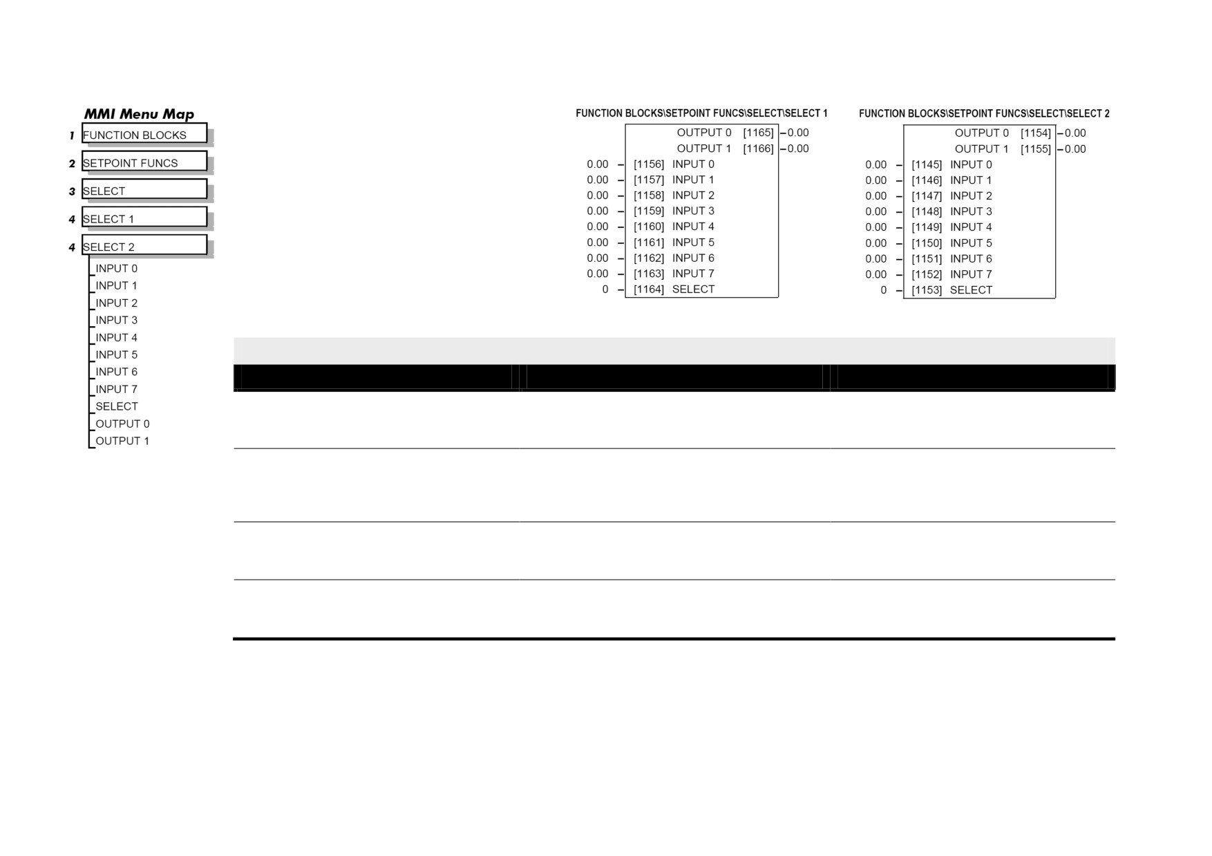
SELECT
Used to select a value from one of eight inputs,
depending on the value of the select input. A second
output is provided to allow the block to be used as
two banks of four inputs.
SELECT
Parameter
Tag
Range
INPUT 0 to INPUT 7
1156 to 1163
-32768.00 to 32768.00
Inputs to the select block
SELECT
1164
0 to 7
Determines which of the inputs is routed to OUTPUT 1 . In addition, if SELECT INPUT is in the range 0 to 3, INPUT 4 to INPUT 7 respectively is
routed to OUTPUT 2, otherwise OUTPUT 2 is unchanged.
OUTPUT 0
1165
.xx
Selected output
OUTPUT 1
1166
.xx
Alternative selected output from INPUT 4 to INPUT 7 if SELECT is less than 4.
Programming D-111
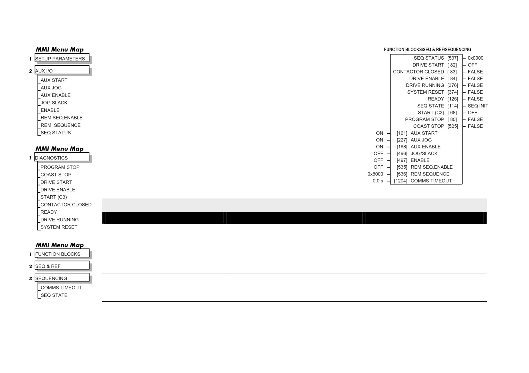
SEQUENCING
This function block contains all the parameters relating to the sequencing (start and stop) of
the drive.
SEQUENCING
Parameter
Tag
Range
AUX START
161
OFF / ON
Software Start/Run command. Auxiliary Start is ANDed with the Start input, C3, to generate Drive Start. This should normally be left ON.
AUX JOG
227
OFF / ON
Software Jog command. Auxiliary Jog is ANDed with the Jog input, Tag 496 (by default C4), to generate Drive Jog. This should normally be left
ON.
AUX ENABLE
168
OFF / ON
Software Enable command. Auxiliary Enable is ANDed with the Enable input, Tag 497 (by default C5), to generate Drive Enable. This should
normally be left ON.
D-112 Programming
SEQUENCING
Parameter
Tag
Range
JOG/SLACK
496
OFF / ON
Main jog input which is connected to DIGITAL INPUT C4 by default. The Jog input is ANDed with Auxiliary Jog input, Tag 227, to generate Drive
Jog.
ENABLE
497
OFF / ON
Enable input which is connected to DIGITAL INPUT C5 by default. The Enable input is ANDed with Auxiliary Enable input, Tag 168, to generate
Drive Enable.
REM.SEQ.ENABLE
535
FALSE / TRUE
(Refer to Chapter 4: "External Control of the Drive"). When enabled, the drive will accept Sequencing commands exclusively from the REM.
SEQUENCE parameter, Tag 536.
FALSE - disables REM. SEQUENCE
TRUE - enables REM. SEQUENCE
REM.SEQUENCE
536
0x0000 to 0xFFFF
A control word that allows the device to be operated remotely over a field bus.
REM. SEQ. ENABLE must be TRUE to enable this function. (Refer to Chapter 4: "External Control of the Drive")
COMMS TIMEOUT
1204
0.0 to 60.0 s
A watchdog timeout that may be used when the drive is in remote sequencing mode. The watchdog feature is enabled by selecting a non-zero time in
this parameter. The watchdog is reset every time the REM.SEQUENCE word, (Tag 536), is written.
SEQ STATUS
537
0x0000 to 0xFFFF
An data word that reports the status of the important system flags that can be read over a field bus. (Refer to Chapter 4: "External Control of the
Drive")
DRIVE START
82
OFF / ON
Logical OR of the START and JOG inputs.
CONTACTOR CLOSED
83
FALSE / TRUE
When ON, the main contactor coil is energised. Refer to Terminal Information for D5 & D6 in Appendix E: "Technical Specifications" - Terminal
Information.
DRIVE ENABLE
84
FALSE / TRUE
Drive speed and current loop are enabled/quenched.
DRIVE RUNNING
376
FALSE / TRUE
When TRUE, the stack is switched on and enabled.
Programming D-113
SEQUENCING
Parameter
Tag
Range
SYSTEM RESET
374
FALSE / TRUE
Set for one cycle as the drive is enabled.
READY
125
FALSE / TRUE
The drive is ready to accept an enable signal.
SEQ STATE
114
See below
0: SEQ INIT
1: SEQ INIT
2: SEQ HOLD
3: SEQ STANDBY
4: SEQ PRE READY
5: SEQ READY
6: SEQ AUTOTUNING
7: SEQ RUN
8: SEQ AT ZERO SPD.
9: SEQ QUENCH
10: SEQ PROGRAM STOP
11: SEQ STOP
12: SEQ DELAY STOP
13: CURRENT DECAY
14: SEQ COAST STOP
15: SEQ ERROR
START (C3)
68
OFF / ON
State of the Start/Run terminal.
PROGRAM STOP
80
FALSE / TRUE
State of program stop (Terminal B8). When B8 is at 24V, then PROGRAM STOP is FALSE.
COAST STOP
525
FALSE / TRUE
State of coast stop (Terminal B9). When B9 is at 24V, then COAST STOP is FALSE.
D-114 Programming
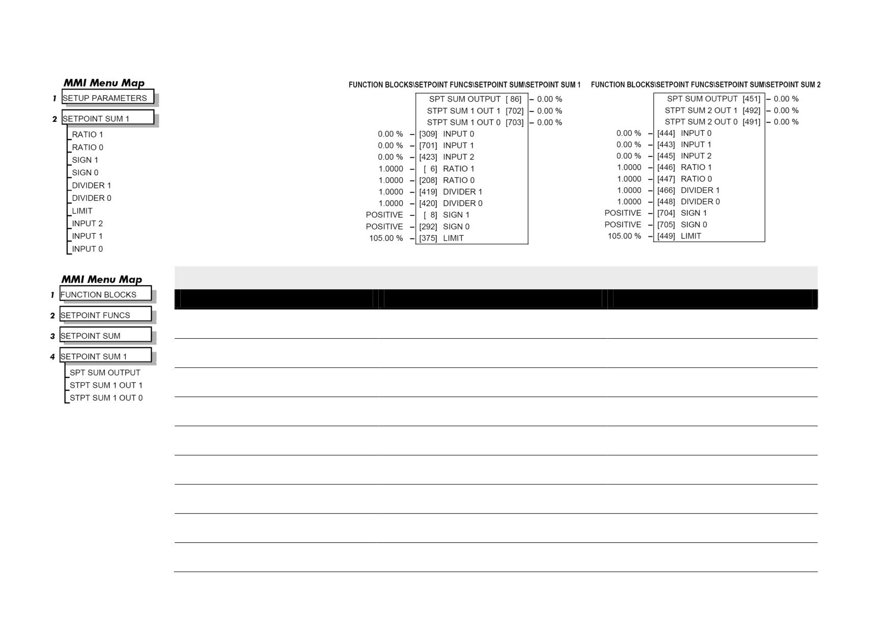
SETPOINT SUM
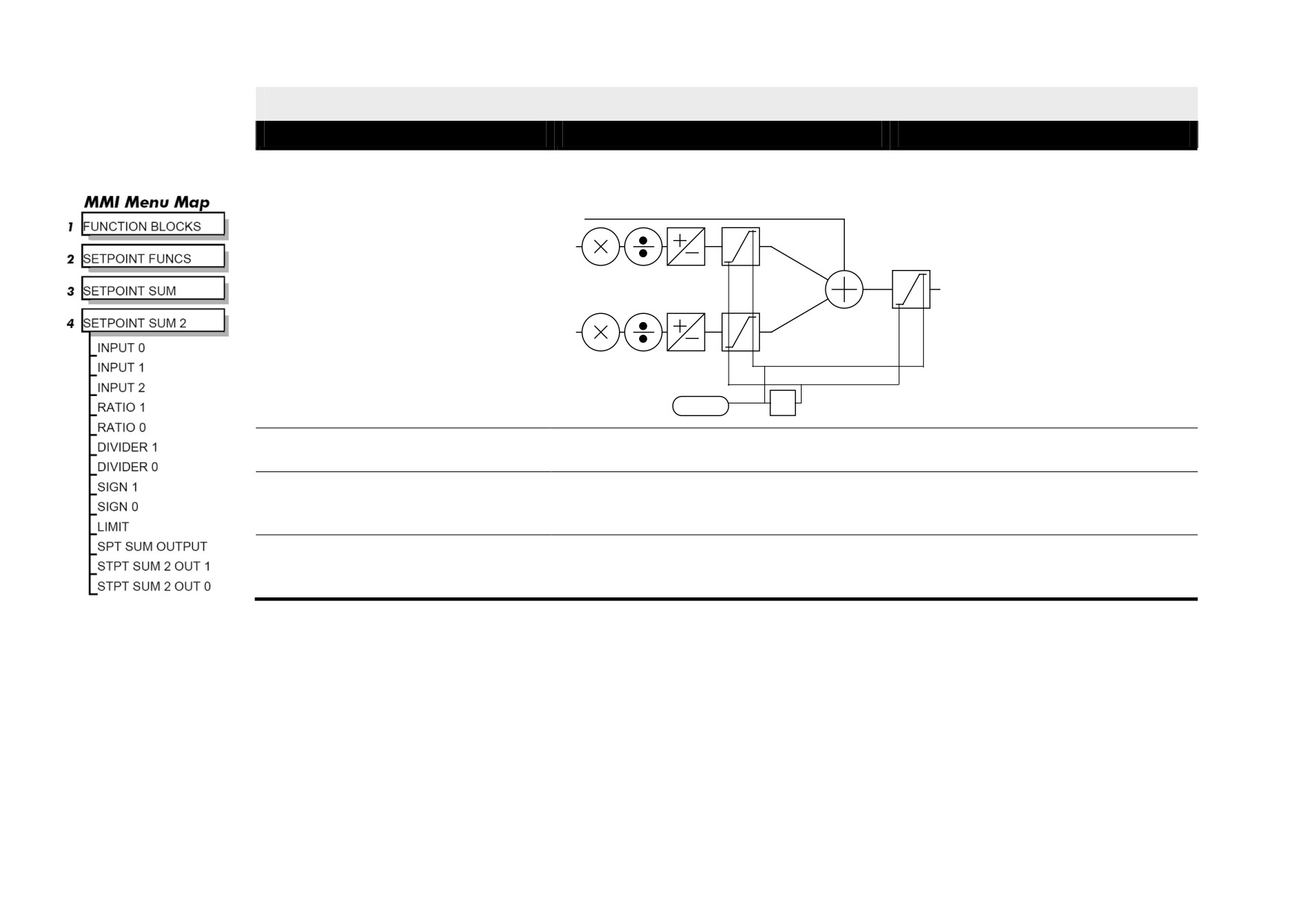
Use this menu to sum and scale up
to three analog inputs to produce
the SPT. SUM output.
INPUT 0 and INPUT 1 have
individual ratio and divider scalers,
and signs. The inputs have
symmetrical limits set by LIMIT.
INPUT 2 has no scaling or limits.
The output, after INPUT 0, INPUT 1
and INPUT 2 are summed, is also
clamped by LIMIT before producing
the SPT. SUM output.
SETPOINT SUM
Parameter
Tag
Range
INPUT 0
309
-300.00 to 300.00 %
Input 0 value.
INPUT 1
701
-300.00 to 300.00 %
Input 1 value.
INPUT 2
423
-300.00 to 300.00 %
Input 2 value.
RATIO 1
6
-3.0000 to 3.0000
Multiplier term for INPUT 1.
RATIO 0
208
-3.0000 to 3.0000
Multiplier term for INPUT 0.
DIVIDER 1
419
-3.0000 to 3.0000
Divider scaling for INPUT 1. Dividing by 0 (zero) results in a zero output.
DIVIDER 0
420
-3.0000 to 3.0000
Divider scaling for INPUT 0. Dividing by 0 (zero) results in a zero output.
SIGN 1
8
NEGATIVE / POSITIVE
Polarity for INPUT 1.
SIGN 0
292
NEGATIVE / POSITIVE
Polarity for INPUT 0.
Programming D-115
SETPOINT SUM
Parameter
Tag
Range
LIMIT
375
0.00 to 200.00 %
The Setpoint Sum programmable limit is symmetrical and has the range 0.00% to 200.00%. The limit is applied both to the intermediate results of
the RATIO calculation and the total output.
INPUT 2
INPUT 1
INPUT 0
LIMIT
-1
SPT SUM OUTPUT
86
.xx %
The sum of input 0, 1 and 2 after the limit clamp.
STPT SUM 1 OUT 1
702
.xx %
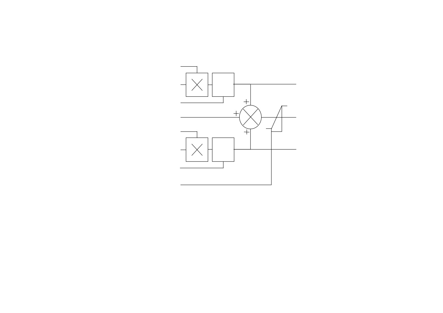
An additional output provided to gain access to Input 1 channel sub-calculations. The result of (INPUT 1 x RATIO 1) / DIVIDER 1 clamped to
within ± LIMIT.
STPT SUM 1 OUT 0
703
.xx %
An additional output provided to gain access to Input 0 channel sub-calculations. The result of (INPUT 0 x RATIO 0) / DIVIDER 0 clamped to
within ± LIMIT.
D-116 Programming
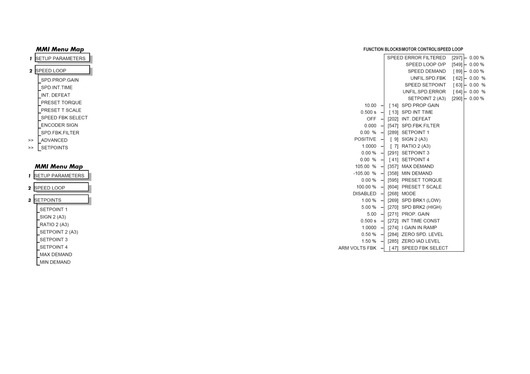
Functional Description
RATIO 0 [447]
INPUT 0 [444]
÷
OUTPUT 0 [491]
DIVIDER 0 [448]
INPUT 2 [445]
MAIN OUTPUT [451]
RATIO 1 [446]
INPUT 1 [443]
÷
OUTPUT 1 [492]
DIVIDER 1 [466]
LIMIT [449]
Programming D-117
SPEED LOOP
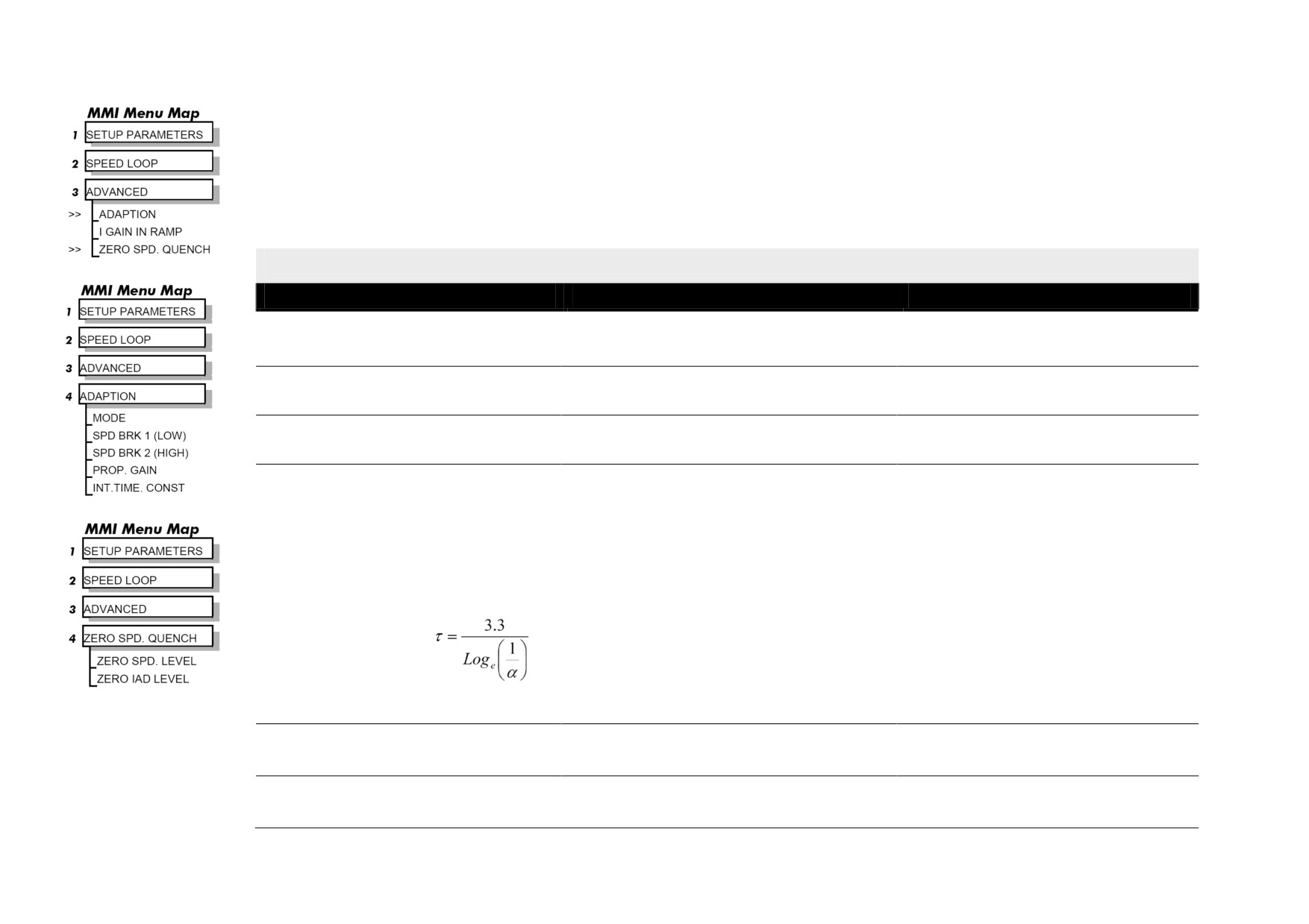
Use this block to tune the speed loop PI to produce a current demand.
This function block has five main functions:
1.
Combining the 4 speed setpoints into a single speed setpoint.
Note that the speed demand is created from the combined speed setpoints and
modified by any prevailing stop condition according to the STOP RATES
function block settings.
2.
Selection of the speed feedback method.
ZERO SPD OFFSET from the CALIBRATION function block is applied to
the selected speed feedback to null out any remaining feedback at zero actual
speed.
3.
Implementation of the PI speed controller.
SPEED DEMAND is summed algebraically with SPEED FEEDBACK to
produce SPEED ERROR. When the drive is enabled, SPEED ERROR is
controlled by the PI loop. The resulting current demand signal is routed to the
CURRENT LOOP function block and to the ADVANCED::ZERO SPD.
QUENCH sub-menu.
The PI output is accessible via Tag No. 356, TOTAL I DMD. This point is
before the I Limit clamps and the summing of the additional current demand.
(This tag is not visible on the MMI).
4.
Speed controller gain and integral time constant profiling with speed.
The gains change when the motor speed feedback reaches the thresholds set
by SPD BRK 1 (LOW) and SPD BRK 2 (HIGH).
• At or below SPD BRK 1 (LOW), the speed loop uses the PROP. GAIN and INT. TIME CONST. values as its PI loop gains.
• Between SPD BRK 1 (LOW) and SPD BRK 2 (HIGH), profiling occurs and the speed loop gains are determined by another parameter
value (according to the selection of the MODE parameter).
• Above SPD BRK 2 (HIGH), the SPD. PROP. GAIN and SPD. INT. TIME settings are used.
MODE selects the parameter for profiling the speed loop PI gains when the motor speed is between the two speed breakpoints.
D-118 Programming
5.
Zero speed/current disabling of thyristor firing
The current loop is disabled when SPEED DEMAND, SPEED FEEDBACK and CURRENT DEMAND have all dropped to the threshold
levels set by ZERO SPD. LEVEL and ZERO IAD LEVEL.
This is similar to Standstill logic (it stops making current but the contactor stays energised) except that the speed loop remains enabled and
this will cause the current loop to unquench very quickly.
SPEED LOOP
Parameter
Tag
Range
SPD PROP GAIN
14
0.00 to 200.00
Speed loop PI proportional gain adjustment.
SPD INT TIME
13
0.001 to 30.000 s
Speed loop PI integral gain adjustment.
INT. DEFEAT
202
OFF / ON
When ON it inhibits the integral part of the speed loop PI control to give proportional only control.
SPEED FBK FILTER
547
0.000 to 1.000
(SPD.FBK.FILTER)
A simple filter function that is applied to speed feedback to reduce ripple caused by low line count encoders and noisy tachos. A value of 0 disables
the filter action ,and 1.00 is the maximum value. A typical value would be between 0.5 and 0.75.
INCREASING THE FILTER VALUE MAY MAKE THE SPEED LOOP UNSTABLE.
The filter time constant τ in milliseconds can be calculated from the following equation:
Where α is the value of SPD FBK FILTER. A value of 0.5 equates to a filter time of 4.8ms, 0.8 to 14.7ms, and 0.9 to 31.2ms.
SETPOINT 1
289
-105.00 to 105.00 %
Speed Setpoint 1 (Default Setpoint Sum 1 O/P).
SIGN 2 (A3)
9
NEGATIVE / POSITIVE
Speed Setpoint 2 Sign.
Programming D-119
SPEED LOOP
Parameter
Tag
Range
RATIO 2 (A3)
7
-3.0000 to 3.0000
Speed Setpoint 2 Ratio.
SETPOINT 3
291
-105.00 to 105.00 %
Speed Setpoint 3 (Default Ramp O/P).
SETPOINT 4
41
-105.00 to 105.00 %
Speed Setpoint 4 (Default 5703 I/P).
MAX DEMAND
357
0.00 to 105.00 %
Sets the maximum input to the speed loop. It is clamped at 105% to allow for overshoot in the external loops.
MIN DEMAND
358
-105.00 to 105.00 %
Sets the minimum input to the speed loop.
PRESET TORQUE
595
-200.00 to 200.00 %
The PRESET TORQUE is pre-loaded into the speed loop integral store as the speed loop in enabled. This is scaled by PRESET T SCALE.
This may be used to pre-load the output of the speed loop in elevator/hoist applications to prevent the load from falling back when the brake is
released. PRESET T SCALE may be used in situations where the load may vary.
PRESET T SCALE
604
-200.00 to 200.00 %
Scaler for PRESET TORQUE.
MODE
268
See below
Selects the speed breakpoint input signal.
0 : DISABLED
1 : SPD FBK DEP
Speed Feedback Dependent
2 : SPD ERR DEP
Speed Error Dependent
3 : CUR DMD DEP
Current Demand Dependent
SPD BRK 1 (LOW)
269
0.00 to 100.00 %
Speed breakpoint 1 to start gain profiling.
SPD BRK 2 (HIGH)
270
0.00 to 100.00 %
Speed breakpoint 2 to stop gain profiling.
D-120 Programming
SPEED LOOP
Parameter
Tag
Range
PROP. GAIN
271
0.00 to 200.00
Proportional gain used below SPD BRK 1 (LOW)
INT. TIME CONST.
272
0.001 to 30.000 s
Integral time constant used below SPD BRK 1 (LOW)
I GAIN IN RAMP
274
0.0000 to 2.0000
This scales the integral gain when the drive is ramping. When RAMPING (Tag No. 113) is TRUE, the integral gain from ADAPTION is switched
through the I GAIN IN RAMP scaler. This can be used to help prevent integral wind-up while the drive is ramping (particularly high inertia loads).
ZERO SPD. LEVEL
284
0.00 to 200.00 %
Sets the threshold of SPEED DEMAND and SPEED FEEDBACK for suspending the current output.
ZERO IAD LEVEL
285
0.00 to 200.00 %
Sets the current demand threshold for suspending the current output.
SPEED ERROR FILTERED
297
.xx %
Refer to Chapter 6: "The Keypad" - The Keypad Menus (DIAGNOSTICS).
SPEED LOOP O/P
549
.xx %
Refer to Chapter 6: "The Keypad" - The Keypad Menus (DIAGNOSTICS).
SPEED DEMAND
89
.xx %
Refer to Chapter 6: "The Keypad" - The Keypad Menus (DIAGNOSTICS).
UNFIL.SPD.FBK
62
.xx %
Refer to Chapter 6: "The Keypad" - The Keypad Menus (DIAGNOSTICS).
SPEED SETPOINT
63
.xx %
Refer to Chapter 6: "The Keypad" - The Keypad Menus (DIAGNOSTICS).
UNFIL.SPD.ERROR
64
.xx %
Refer to Chapter 6: "The Keypad" - The Keypad Menus (DIAGNOSTICS).
SETPOINT 2 (A3)
290
.xx %
Speed Setpoint 2 - Fixed (non-configurable) setpoint scanned synchronously with the current loop
Programming D-121
SPEED LOOP
Parameter
Tag
Range
SPEED FBK SELECT
47
See below
Determines the source of the speed feedback signal. The default, ARM VOLTS FBK, uses internal circuitry to derive the speed feedback. The other
selections require the appropriate external device to provide the feedback signal.
0 : ARM VOLTS FBK
1 : ANALOG TACH
2 : ENCODER
3 : ENCODER/ANALOG - for Parker SSD Drives use
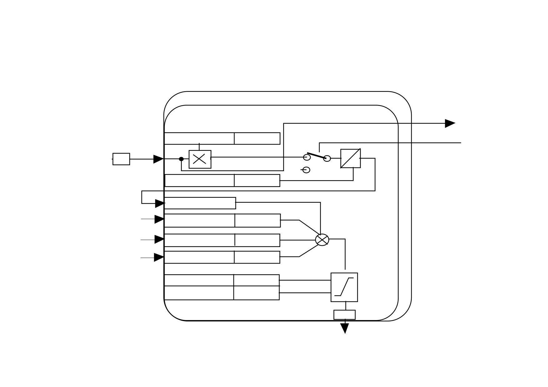
Functional Description
Speed Loop PI with Current Demand Isolate
The speed loop output is still valid (active) with the I DMD. ISOLATE parameter enabled.
NOTE
1
The speed loop is reset by unquenching the speed loop/current loop.
2
I DMD. ISOLATE is overridden by Program Stop (B8) or Normal Stop (C3).
3
The speed loop PI holds the integral term as soon as the PI output reaches current limit. This is true even in Current Demand Isolate
mode where it may interfere depending on the way the speed PI is used. This feature is currently not suppressible.
D-122 Programming
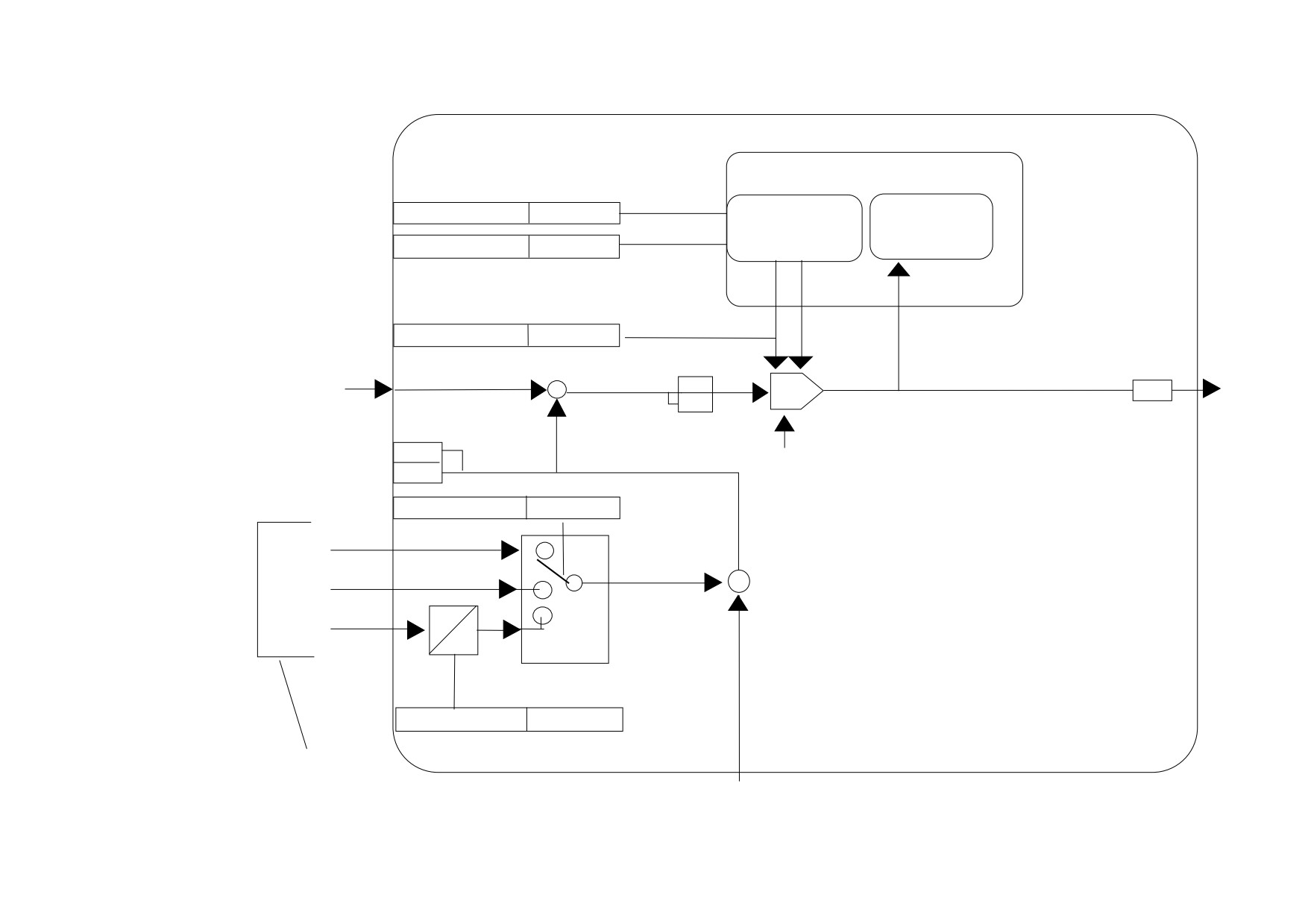
105% Speed Demands
The speed demand clamping allows the speed setpoint to reach 105%. This applies only to the final summing junction immediately before the speed
loop and also to the Setpoint Sum 1 output. Individual speed setpoints are still clamped to 100%.
TO CURRENT LOOP
SETPOINTS
(I DEMAND ISOLATE
SWITCH)
TAG# PARAMETER
DEFAULT
SETTING
7 RATIO 2 (A3)
1,0000
ANALOG I/P 2
FROM CURRENT LOOP
+
A3
-
I DMD ISOLATE
9 SIGN 2 (A3)
POSITIVE
290 SETPOINT 2
FROM
41 SETPOINT 4
5703 RATIO
5703 SUPPORT
+
+
FROM
289 SETPOINT 1
SPT. SUM O/P
+
SETPOINT SUM
+
FROM
291 SETPOINT 3
RAMP OUTPUT
RAMPS
357 MAX DEMAND
105.00%
358 MIN DEMAND
-105.00%
SPEED
SETPOINT
63
TO STOP RATES (PROGRAM STOP AND NORMAL STOP RAMPS TO ZERO SPEED
Programming D-123
SPEED LOOP
DEFAULT
ADAPTION
ZERO SPD. QUENCH
TAG# PARAMETER
SETTING
14 PROP. GAIN
10.00
GAIN AND INTEGRAL
PROFILING
13 INT. TIME CONST
0.500 SECS
202 INT. DEFEAT
TO CURRENT LOOP
OFF
SPEED
IDMD ISOLATE
(SPEED SETPOINT
ERROR
AFTER STOP RATES
+
SWITCH I/P
SPEED
RAMP TO ZERO
64
PI
356
DEMAND
-
297
SPEED
FEEDBACK
207
NOTE
DRIVE
ENABLE
62
ENCODER/ANALOG FEEDBACK SELECTION USED
ANALOG TACH FEEDBACK FOR THE PROPORTIONAL
47 SPEED FBK SELECT
ARM VOLTS
TERM OF THE SPEED LOOP PI, AND ENCODER
FEEDBACK FOR THE INTEGRAL TERM. THIS FEEDBACK
ARM
SELECTION REQUIRES A COMBINATION ANALOG TACH/
VOLTS
ENCODER FITTED TO THE MOTOR.
+
THIS SELECTION CANNOT BE USED WHEN 590 SWITCHABLE
ANALOG
-
TACHO CARD IS FITTED.
TACH
+
ENCODER
_
ENCODER/ANALOG
SEE NOTE
49 ENCODER SIGN
POSITIVE
FROM
CALIBRATION
ZERO SPD OFFSET
FROM CALIBRATION
D-124 Programming
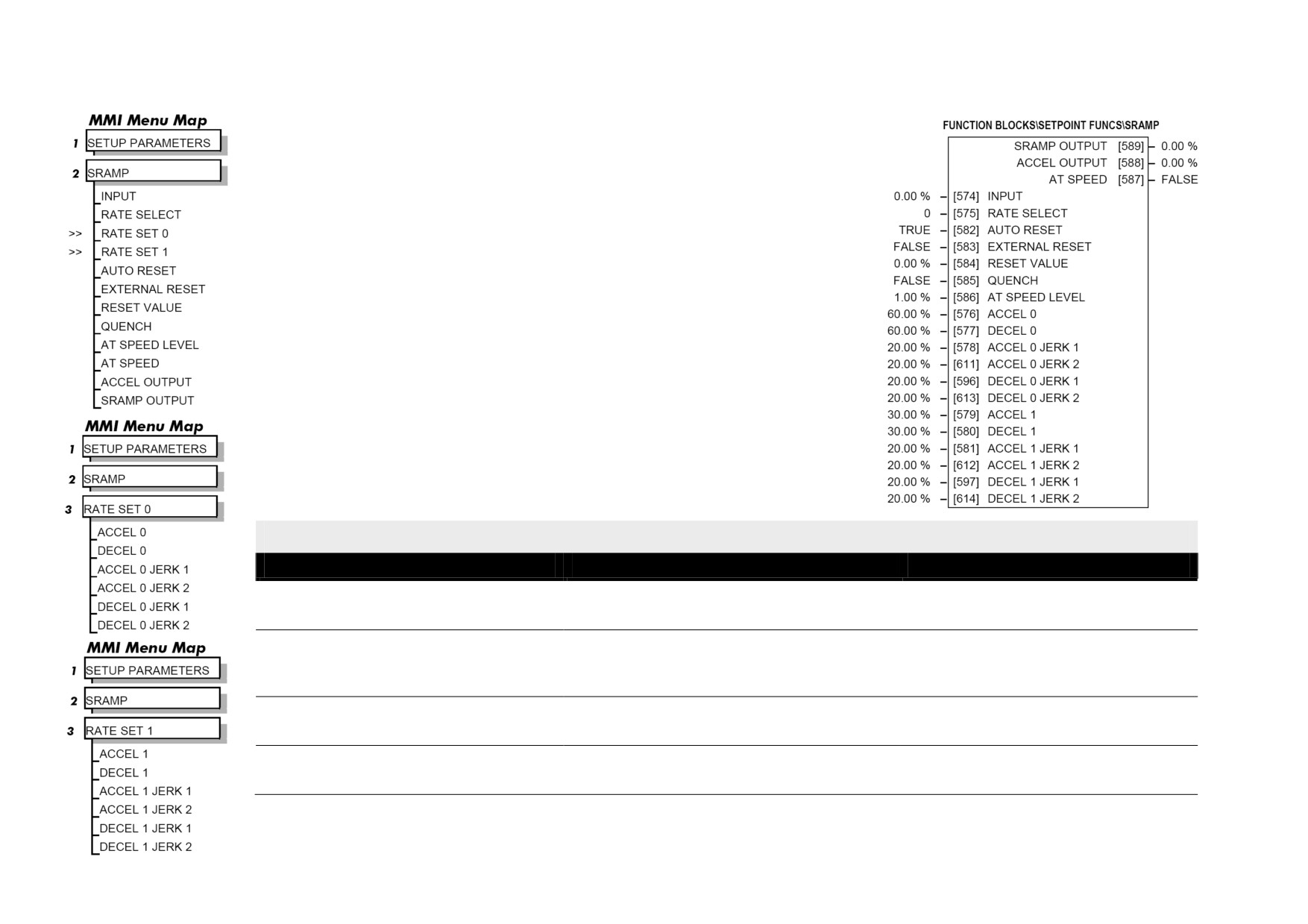
SRAMP
This function block limits the rate of change of an input by limiting the acceleration and
the jerk (rate of change of acceleration).
SRAMP
Parameter
Tag
Range
INPUT
574
-100.00 to 100.00 %
Input value.
RATE SELECT
575
0 to 1
Selects between one of two parameter sets. This allows you to have two operating modes (RATE SET 0 or RATE SET 1) with independent ramp
parameters.
AUTO RESET
582
FALSE / TRUE
The ramp is reset automatically when the drive is enabled if set to TRUE.
EXTERNAL RESET
583
FALSE / TRUE
Resets the ramp output.

Programming D-125
SRAMP
Parameter
Tag
Range
RESET VALUE
584
-100.00 to 100.00 %
The output value while RESET is TRUE also used as initial value on start up. If this is linked to speed feedback, the initial ramp output will be set
to the current value of speed feedback.
QUENCH
585
FALSE / TRUE
If TRUE forces the ramp input to zero.
AT SPEED LEVEL
586
0.00 to 100.00 %
Threshold for AT SPEED diagnostic output.
ACCEL 0
576
0.00 to 100.00 %
Acceleration rate, in units of percent per second2. i.e. 75.00 % means that the maximum acceleration will be 75.00% per second2 if the full speed of
the machine is 1.25ms then the acceleration will be 1.25 * 75.0% = 0.9375ms2 .
DECEL 0
577
0.00 to 100.00 %
Deceleration rate, only active if SYMMETRIC = TRUE.
ACCEL 0 JERK 1
578
0.00 to 100.00 %
Rate of change of acceleration, in units of percent per second3.
For example: 75.00 % means that the maximum acceleration will be 50.00% per second3 if the full speed of the machine is 1.25ms then the
acceleration will be 1.25 * 50.0% = 0.625ms3.
If SYMMETRIC = TRUE then this value will be used for each of the four segments of the profile.
If SYMMETRIC = TRUE then this value will be used only for the first acceleration segment.
ACCEL 0 JERK 2
611
0.00 to 100.00 %
Rate of change of acceleration in units of percent per second3 for segment 2. Only applicable if SYMMETRIC = FALSE.
DECEL 0 JERK 1
596
0.00 to 100.00 %
Rate of change of acceleration in units of percent per second3 for segment 3. Only applicable if SYMMETRIC = FALSE.
DECEL 0 JERK 2
613
0.00 to 100.00 %
Rate of change of acceleration in units of percent per second3 for segment 4. Only applicable if SYMMETRIC = FALSE.
ACCEL 1
579
0.00 to 100.00 %
Refer to ACCEL 0.
DECEL 1
580
0.00 to 100.00 %
Refer to DECEL 0.
ACCEL 1 JERK 1
581
0.00 to 100.00 %
Refer to ACCEL 0 JERK 1.