Parker 590+ series Frame 1, 2, 3, 4, 5, 6 & H. Product Manual (2012) - page 17

Certification B-1
Introduction
Our Drives are certified as being compliant with the regulated market requirements in:
Europe
Drives are CE certified as being compliant with
• The Low Voltage Directive 2006/95/EC
• The EMC Directive 2004/108/EC
USA
• Underwriters Laboratory Standard UL508c for Power Conversion Equipment
Canada
• Canadian Standards Association C22.2 No.14 for Industrial Control Equipment
Australia & New Zealand
• CTick mark indicating EMC compliance is validated by compliance with the European Harmonised
Standards for EMC
Rest of the world
• Compliance may be certified for any countries where certification is based on CISPR (IEC) standards
Europe
What are the European Directives?
The Directives are created to allow manufacturers to trade freely within the EEC territory through technical harmonisation of entire product sectors,
and by guaranteeing a high level of protection of public interest objectives. This is done by creating a CE marking
, a "trade symbol" showing that
the technical requirements and those for safety and health are met.
Business and industry are given a wide choice of how to meet their obligations. The European standards bodies have the task of drawing up technical
specifications. Compliance with harmonised standards, of which the reference numbers have been published in the Official Journal and which have
been transposed into national standards, provides presumption of conformity to the corresponding essential requirements of the EC directives.
Manufacturers are free to choose any other technical solution that provides compliance with the essential requirements. Compliance with harmonised
standards remains voluntary and offers one route to complying with these essential requirements.

B-2 Certification
The Declaration of Conformity signed by the companies nominated Compliance Officer is certification that the apparatus to which it refers meets the
requirements of all the relevant European directives.
Compliance with harmonised standards provides a "presumption of conformity” and is the route which has been adopted by Parker SSD Drives.
CE Marking for the Low Voltage Directive (LVD) 2006/95/EC
The Low Voltage Directive (LVD) 2006/95/EC1 seeks to ensure that electrical equipment within certain voltage limits provides both a high level of
protection for European citizens and enjoys a Single Market in the European Union. The Directive covers electrical equipment designed for use with a
voltage rating of between 50 and 1000V for alternating current and between 75 and 1500V for direct current. For most electrical equipment, the health
aspects of emissions of Electromagnetic Fields are also under the domain of the Low Voltage Directive.
The LVD is one of the oldest Single Market Directives which, in broad terms, provides both a conformity assessment procedure to be applied to
equipment before being placed on the Market, and Essential Health Safety Requirements (EHSRs) which such equipment must meet either directly or
by means of compliance with harmonized standards.
For electrical equipment within its scope, the Directive provides ‘The Requirements’ with respect to health and safety covering all risks, thus ensuring
that electrical equipment is safe in its intended use.
In respect of conformity assessment, there is no third party intervention, as the manufacturer undertakes the conformity assessment. However, there are
so-called "Notified Bodies" under the Directive, which may be used to provide reports in response to a challenge by a national authority as to the
conformity of the equipment.
When installed in accordance with this manual, the product is CE marked by Parker SSD Drives in accordance with the Low Voltage Directive
Parker SSD Drives' certification (DoC) is supported by tests undertaken in accordance with harmonised standard BS EN61800-5-1
CE Marking for the EMC Directive 2004/108/EC
The aim of the EMC Directive 2004/108/EC2 is to ensure that any electric or electronic device will create no more then a limited amount of RF
interference such that other apparatus are not prevented from functioning correctly, also to ensure that an electric or electronic device will withstand a
certain amount of Electro Magnetic interference from within its working environment.
1
Directive 73/23/EEC has recently been the subject of a codification, requiring a new number 2006/95/EC. Readers should note that the text itself is
identical.
2
Directive 89/336/EEC has been superseded by Directive 2004/108/EC which came into effect on 15th December 2004.
Certification B-3
Provisions have been put in place so that:
• Equipment (apparatus 3 and fixed installations 4) needs to comply with the requirements of the EMC Directive when it is placed on the market
and/or taken into service.
• The application of good engineering practice is required for fixed installations, with the possibility for the competent authorities of Member
States to impose measures if non-compliances are established.
The directive text makes a clear distinction between the requirements and assessment procedures for apparatus and for fixed installations respectively
(fixed installations can include networks and large machines).
• Fixed installations, although they must comply with the protection requirements, require neither an EC Declaration of Conformity (DoC) nor
CE marking;
• Mobile installations are considered apparatus.
The conformity assessment procedure for apparatus has been simplified to a single procedure. There is no compulsory involvement of a third party, but
the manufacturer has the option of presenting his technical documentation to a Notified Body for assessment.
When deviating from the European harmonized standards or not applying them fully, the manufacturer has to perform an EMC assessment and provide
detailed documentary evidence that the apparatus complies with the protection requirements of the EMC Directive.
Apparatus intended for a given fixed installation and not otherwise commercially available may be exempt from the requirements and procedures for
apparatus (e.g. EC Declaration of Conformity and CE marking), provided that certain documentation requirements are met, including precautions to be
taken in order not to compromise the EMC characteristics of the fixed installation.
BS EN 61800-3 defines the emissions and immunity levels for Power drive systems (PDS) and the main component parts of such a system (Basic drive
module and Complete drive module).
The standard defines specific categories of PDS:
PDS of Category C1
PDS of rated voltage less than 1000V, intended for use in the first environment
PDS of Category C2
PDS of rated voltage less than 1000V, which is neither a plug in device nor a movable device and, when used in the first environment, is
intended to be installed and commissioned only by a professional.
NOTE a professional is a person or organisation having necessary skills in installing and/or commissioning power drive systems,
including their EMC aspects.
3
‘Apparatus’ means any finished appliance or combination thereof made commercially available as a single functional unit, intended for the end user and
liable to generate electromagnetic disturbance, or the performance of which is liable to be affected by such disturbance.
4
‘Fixed installation’ means a particular combination of several types of apparatus and where applicable other devices, which are assembled, installed and
intended to be used permanently at a predefined location.

B-4 Certification
PDS of Category C3
PDS of rated voltage less than 1000V, intended for use in the second environment and not intended for use in the first environment
PDS of Category C4
PDS of rated voltage equal to or above 1000V, or rated current equal to or above 400A, or intended for use in complex systems in the second
environment
The drive is generally a category C3 apparatus. Some of the equipments with higher ratings might be classified in Category C4; but for certification,
and as an aid to builders of complex system, the emission limits and immunity levels associated with category C3 have been applied.
Parker SSD Drives' certification (DoC) is supported by tests undertaken in accordance with harmonised standard BS EN61800-3
United States of America & Canada
Compliance
The US have many municipalities that have laws, codes or regulations which require a product to be tested by a nationally recognized testing
laboratory before it can be sold in their area. Parker SSD Drives adopt the nationally recognised Underwriters Laboratories (UL) mark to demonstrate
compliance.
Products are also certified for the Canadian market obtained through UL and their memorandum of understanding with the Canadian Standards
Agency (CSA).
Parker SSD Drives obtain product certification to UL508C “Power Conversion Equipment” for the US market, and C22.2 No.14 “Industrial Control
Equipment” for the Canadian market.
Conditions for Compliance with UL508c
Solid-State Motor Overload Protection
NOTE An external motor overload protective device must be provided by the installer.
The maximum internal overload protection level (current limit) is 150% for 30 seconds and 200% for 10 seconds.
Motor overload protection is provided by means of the thermal device in the motor winding. This protection cannot be evaluated by UL, hence it is the
responsibility of the installer and/or the local inspector to determine whether the overload protection is in compliance with the National Electrical Code
or Local Code requirements.
Certification B-5
Branch Circuit/Short Circuit Protection Requirements
The controller requires branch circuit protection. Branch circuit protection requirements must be in accordance with the latest addition of the National
Electrical Code, NEC/NFPA-70.
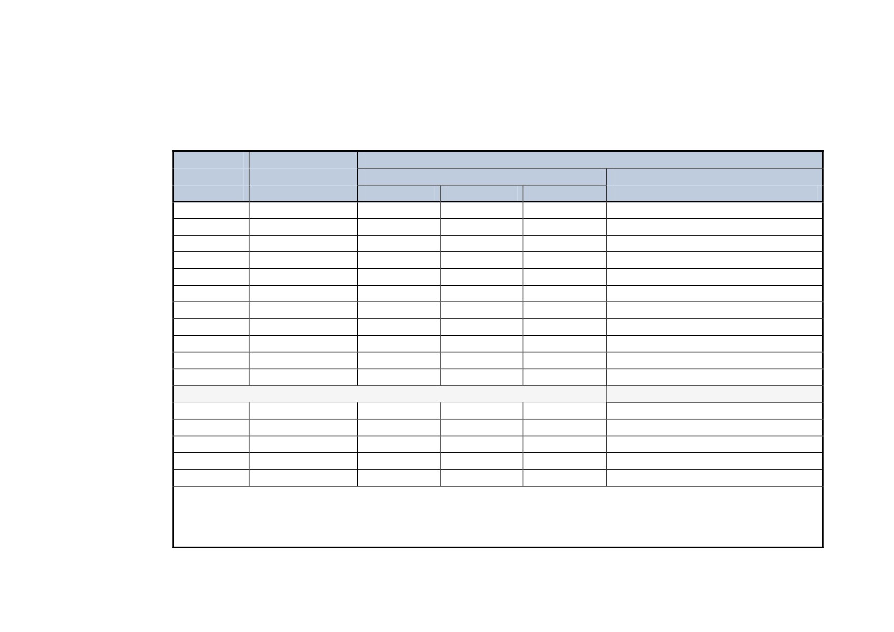
UL Recognized Component (JFHR2) semiconductor fuses with current ratings and maximum I2t ratings as specified below must be used in the
controller. Refer to the table below for the recommended fuse manufacturer and part number.
Controller Rating
Input Line Semiconductor Fuses
Motor HP @
Ratings
Part No. Gould
500V dc
(A)
(Vac)
(A)
I
2t (A2s)
or equivalent*
7.5
15
500
31.3
750
A60Q35
20
35
500
31.3
750
A60Q35
20
40
500
31.3
750
A60Q35
30
70
500
71.6
1300
A50QS80-4R
40
70
500
71.6
1300
A50QS80-4R
50
110
500
111.8
2860
A50QS125-4R
60
110
500
111.8
2860
A50QS125-4R
75
165
500
156.6
7540
A50QS200-4R
100
165
500
156.5
7540
A50QS200-4R
50 ●
180
500
?
?
150
270
500
?
?
Part No. Bussmann or equivalent*
200
380
660
550
135000
170M6809
300
500
660
700
300000
170M6811
400
725
660
900
670000
170M6813
500
830
660
1000
945000
170M6814
900
1580
660
2 x 1000
945000
170M6814
* Other UL Recognized Component (JFHR2) semiconductor fuses may be used in the controller provided that the voltage, ampere and I
2t
ratings shown above are not exceeded.
● Rated armature voltage: 240V dc
NOTE Semiconductor fuses are acceptable as branch circuit short-circuit protection for the solid-state motor controllers only.
Table B- 1 Short Circuit Protection Requirements
B-6 Certification
Short Circuit Rating
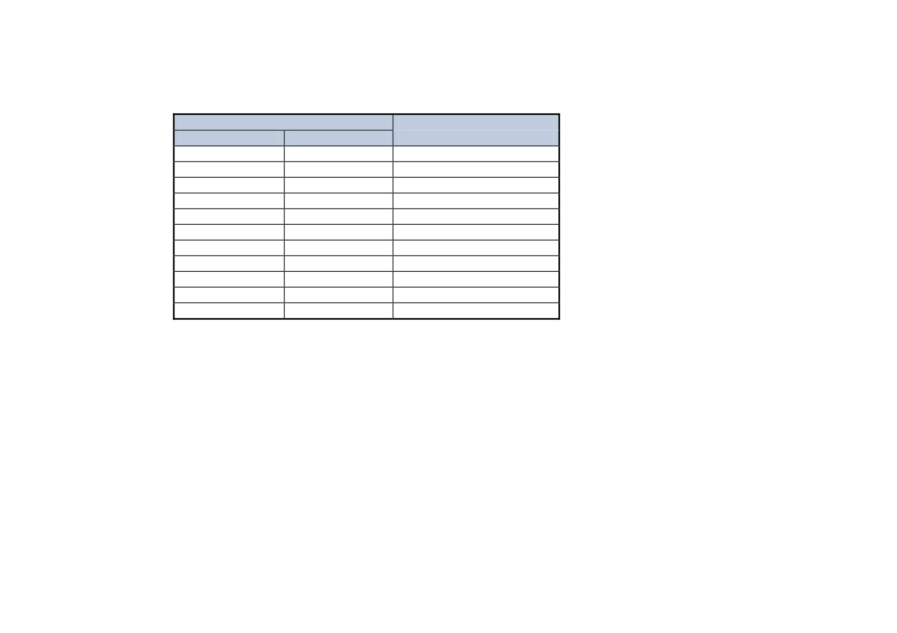
These products are suitable for use on a circuit capable of delivering not more than (the value shown in Table 12-2) RMS Symmetrical Amperes, 500V
maximum.
Output Ratings
Short Circuit Rating
(A)
(kW ) 500V
RMS Symmetrical Amperes
15
7.5
5,000
35
15
5,000
40
15
10,000
70
30
10,000
110
45
10,000
165
75
10,000
380
150
18000
500
225
18000
725
327
30000
830
335
30000
1580
650
85000
Table B- 2 Short Circuit Ratings
Field Wiring Temperature Rating
Use 75°C copper conductors only.
Operating Ambient Temperature
For the operating ambient temperature range, refer to Appendix E: “Technical Specifications” - Environmental Details.
Field Wiring Terminal Markings
For the correct field wiring connections that are to be made to each terminal, refer to Chapter 3: “Installing the Drive” - Electrical Installation.
Power and Control Field Wiring Terminals
For the correct tightening torque value, refer to Appendix E: “Technical Specifications”.
Certification B-7
Field Grounding Terminals
The field grounding terminal(s) is identified with the International Grounding Symbol (IEC) Publication 417, Symbol 5019.
Field Terminal Kits
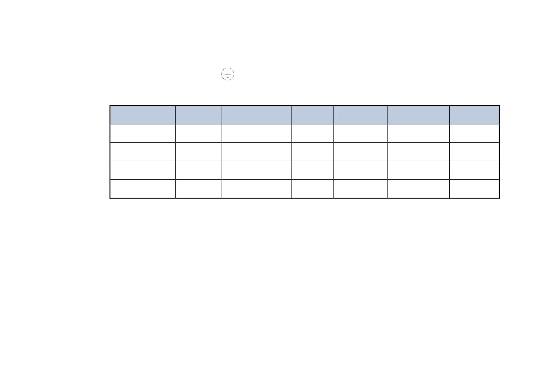
UL compliant terminal kits are available for the connection of power wiring for the following Drive ratings. These terminals must be applied with the
correct tooling as described in the Installation Instructions provided with each terminal kit.
Kit Part Number
Controller
Number of Lugs
Purpose
Lugs per
Wire Size per Lug
Cable Rating
Rating (A)
Terminal
LA386000U380
380
3
AC
1
2 x 4/0 AWG
230A
2
DC
1
2 x 250kcmil
255A
LA386000U500
500
3
AC
1
2 x 300kcmil
285A
2
DC
1
2 x 350kcmil
310A
LA386000U725
725
3
AC
1
2 x 600kcmil
420A
4
DC
2
2 x 4/0 AWG
230A
LA386000U830
830
6
AC
2
2 x 250kcmil
255A
4
DC
2
2 x 300kcmil
285A
NOTE
1580A controller requires two LA386000U830 kits.
B-8 Certification
Recommended Wire Sizes
North American wire sizes (AWG) are based on NEC/NFPA-70 for ampacities of thermoplastic-insulated (75ºC) copper conductors assuming not
more than three current-carrying conductors in raceway or cable, based on ambient temperature of 40ºC. The wire sizes allow for an ampacity of 125%
of the rated input and output amperes for motor branch-circuit conductors as specified in NEC/NFPA-70.
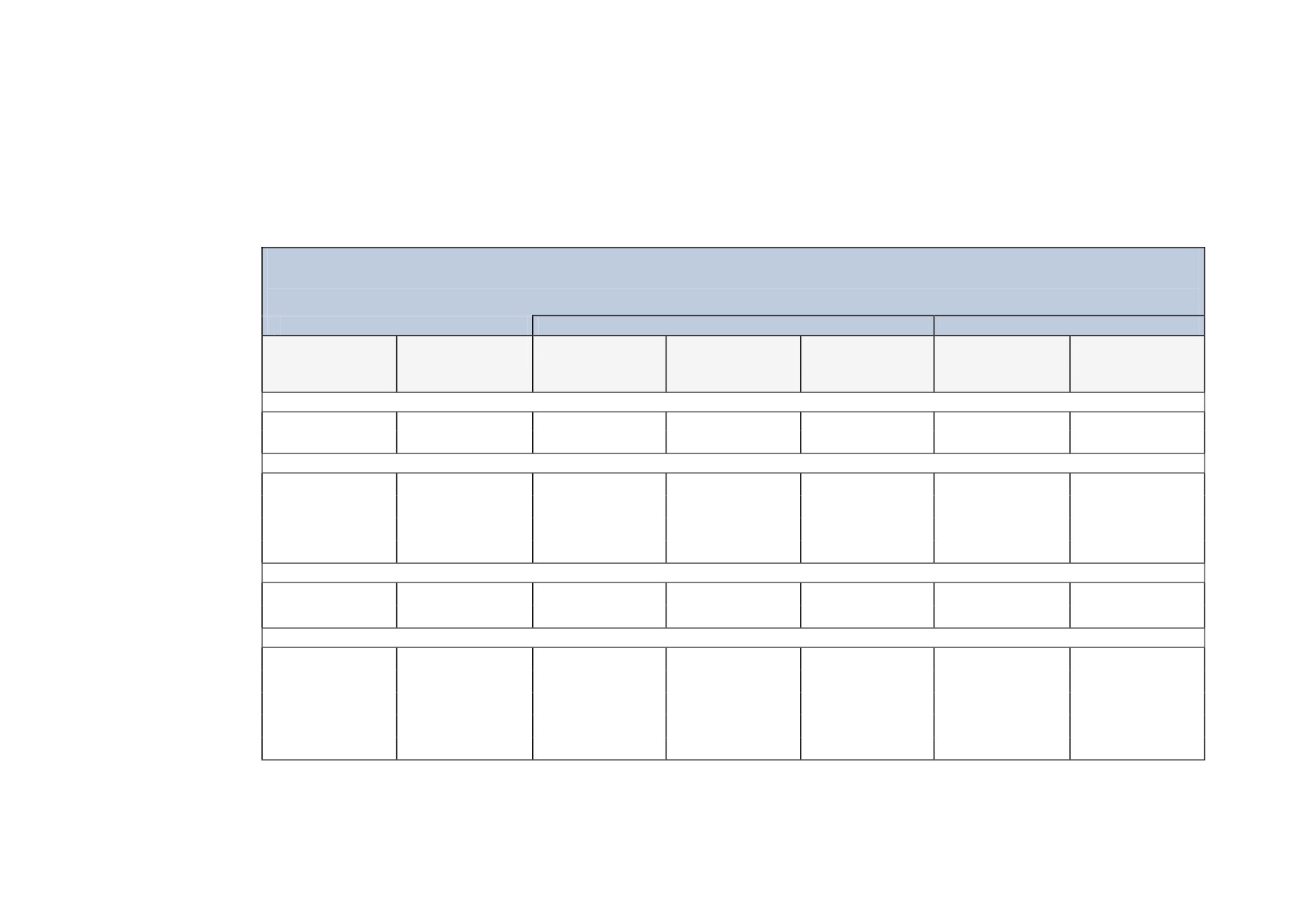
The table below gives the wire sizes for the input (supply) and output (motor) wiring. The table includes the rated input and output amperes for each
model at 460V or 575V operation.
Recommended Wire Sizes (Frames 1, 2, 3, 4 & 5)
Main power wiring. Local wiring regulations always take precedence.
Input
Output
Drive
Input Current
Number of
North American
Output Current
Number of
North American
Size
(A)
Conductors
Wire Size
(A)
Conductors
Wire Size
(A)
Frame 1
15
13.5
1
12 AWG
15
1
12 AWG
35
28.35
1
8 AWG
35
1
8 AWG
Frame 2
40
36
1
8 AWG
40
1
8 AWG
70
63
1
1 AWG
70
1
3 AWG
110
99
1
1 AWG
110
1
1/0 AWG
165
148.5
1
3/0 AWG
165
1
4/0 AWG
Frame 3
180
162
1
4/0 AWG
180
1
4/0 AWG
270
243
1
350 Kcmil
270
1
500 Kcmil
Frame 4 & 5
380
342
1
700 Kcmil
380
1
750 Kcmil
500
450
1
1250 Kcmil
500
1
1500 Kcmil
725
653
1
3 inch bus bar
725
1
3 inch bus bar
830
747
1
3 inch bus bar
830
1
4 inch bus bar
1580
1427
2
4 inch bus bar
1580
2
4 inch bus bar
Certification B-9
Recommended Wire Sizes (Frame 6)
Local wiring regulations always take precedence.
Input
Output
Description
Drive
Input Current
Number of
North American
Output Current
Number of
North American
Size
(A)
Conductors
Wire Size
(A)
Conductors
Wire Size
(A)
(Kcmil)
(Kcmil)
1250
1125
4
500
1250
4
500
Main
1650
1485
6
400
1650
6
500
Power
1950
1755
6
500
1950
6
600
Field
60
60
1
AWG 8
60
1
AWG 8
Recommended Wire Sizes (Frame H)
Local wiring regulations always take precedence.
Input
Output
Description
Drive
Input Current
Number of
North American
Output Current
Number of
North American
Size
(A)
Conductors
Wire Size
(A)
Conductors
Wire Size
(A)
(Kcmil)
(Kcmil)
1200
1100
4
500
1200
4
500
Main
1700
1550
6
400
1700
6
500
Power
2200
2000
6
600
2200
6
700
2700
2450
6
900
2700
8
700
Field
60
60
1
AWG 8
60
1
AWG 8
Field Grounding Terminals
The field grounding terminals are identified with the International Grounding Symbol
(IEC Publication 417, Symbol 5019).
Operating Ambient Temperature
0°C to 40°C (32°F to 104°F), derate up to a maximum of 50°C. Derate linearly at 1% per degree centigrade for temperature exceeding the maximum
rating ambient for the drive.
External Power Semiconductor Protection Fuses
For details on these input fuses, refer to Appendix E: "Technical Specifications".
B-10 Certification
Australia & New Zealand
A Mutual Recognition Agreement in relation to conformity assessment, certificates and markings between Australia and the European Community was
signed on June 1, 1998 and entered into force on January 1, 1999. Sectoral Annexes of the MRA cover: medicinal products, medical devices,
telecommunications terminal equipment, low voltage equipment (i.e. electrical safety), electromagnetic compatibility (EMC), machinery, pressure
equipment and automotive products.
EMC Standards
Extract from Mandatory Australian Communications Authority standards.
Product
European
International
AS/NZS
2064
Industrial, scientific, and medical (ISM) equipment
EN 55011
CISPR 11
Note 3
3548
Information technology equipment
EN 55022
CISPR 22
Note 2
Generic (residential, commercial, and light industry)
EN 50081.1
IEC 61000-6-3
4251.1
Generic (industrial environments)
EN 50081-2
IEC 61000-6-4
4251.2
Adjustable speed electrical power drive systems
EN 61800-3
IEC 61800-3
0
Parker SSD certification (DoC) is supported by tests undertaken in accordance with harmonised standard BS EN61800-3
Certification B-11
EMC
Emissions Limits
Conducted
Frequency (MHz)
DB (μV)
Product Specific
Quasi Peak
Average
EN 61800-3
where I ≤100A
90
100
0.15
- 0.5
76
86
0.5
- 5.0
80
90
5.0
- 30.0
Category C3
decreasing with log of frequency to:
70
Table 17
60
where I ≥100A
0.15
- 0.5
130
120
0.5
- 5.0
125
115
5.0
- 30.0
115
105
Harmonics (Low Frequency Emissions)
I < 75A
61000-3-12
I > 75A
61000-3-4
Harmonic emissions for DC drive installations cannot be predicted here as they are determined by motor parameters that are installation dependent.
For help in determining the harmonics contact Parker SSD Drives.
Where these levels are too high and to ensure compatibility with other equipment, EMC filters are available from Parker SSD Drives.
Radiated
Frequency (MHz)
DB (μV)
Product Specific
Quasi Peak
EN 61800-3
Category C3
30≤ f- ≤230
50
(Table 18)
230≤ f- ≤1000
60
Measured at 10m
Where these levels are too high and to ensure compatibility with other equipment, Parker SSD Drives can advise on suitable counter-measures.
B-12 Certification
EMC Immunity Levels
Basic standard
Performance
Port
Phenomenon
Level
for test method
(acceptance criterion)
Enclosure port
ESD
IEC 61000-4-2
4 kV CD or 8 kV AD
B
if CD impossible
Radio-frequency electromagnetic field, amplitude
IEC 61000-4-3
80 MHz to 1000 Mhz
A
modulated.
see also 5.3.4
10 V/m
80% AM (1 kHz)
Power ports
Fast transient-burst
IEC 61000-4-4
2 kV/5 kHz a
B
Surge b
IEC 61000-4-5
1 kV c
B
1,2/50 µs, 8/20 µs
2 kV d
Conducted radio-frequency common mode e
IEC 61000-4-6
0,15 MHz to 80 MHz
A
see also 5.3.4
10 V
80 % AM (1 kHz)
Power interfaces
Fast transient-burst e
IEC 61000-4-4
2 kV/5 kHz
B
Capacitive clamp
Signal interfaces
Fast transient-burst e
IEC 61000-4-4
1 kV/5 kHz
B
Capacitive clamp
Conducted radio-frequency common mode e
IEC 61000-4-6
0,15 MHz to 80 MHz
A
see also 5.3.4
10 V
80 % AM (1 kHz)
Ports for process
Fast transient-burst e
IEC 61000-4-4
2 kV/5 kHz
B
measurement
Capacitive clamp
control lines
Surge f
IEC 61000-4-5
1 kV d,f
B
1,2/50 µs, 8/20 µs
Conducted radio-frequency common mode e
IEC 61000-4-6
0,15 MHz to 80 MHz
A
see also 5.3.4
10 V
80 % AM (1 kHz)
CD : contact discharge
AD : air discharge AM : amplitude modulation
a
Power ports with current rating < 100 A: direct coupling using the coupling and decoupling network. Power ports with current rating ≥ 100 A: direct coupling
or capacitive clamp without decoupling network. If the capacitive clamp is used, the test level shall be 4 kV/2,5 kHz.
b
Applicable only to power ports with current consumption , 63 A during light load test conditions as specified in 5.1.3. The rated impulse voltage of the basic
insulation shall not be exceeded (see IEC 60664-1).
c
Coupling line-to-line.
d
Coupling line-to-earth.
e
Applicable only to ports or interfaces with cables whose total length according to the manufacturer's functional specification may exceed 3 m.
f
Applicable only to ports with cables whose total length according to the manufacturer's functional specification may exceed 30 m. In the case of a shielded
cable, a direct coupling to the shield is applied. This immunity requirement does not apply to fieldbus or other signal interfaces where the use of surge
protection devices is not practical for technical reasons. The test is not required where normal functioning cannot be achieved because of the impact of the
coupling/decoupling network on the equipment under test (EUT).
Table B- 3 Minimum immunity requirements for PDSs intended for use in the second environment
Certification B-13
EMC General Installation Considerations
Earthing Requirements
IMPORTANT
Protective earthing always takes precedence over EMC screening.
Protective Earth (PE) Connections
NOTE
In accordance with installations to EN60204, only one protective earth conductor is permitted at each protective earth terminal contacting
point.
Local wiring regulations tale precedence and may require the protective earth connection of the motor to be connected locally, i.e. not as specified in
these instructions. This will not cause shielding problems because of the relatively high RF impedance of the local earth connection.
EMC Earth Connections
For compliance with EMC requirements, we recommend that the “0V/signal ground” be separately earthed. When a number of units are used in a
system, these terminals should be connected together at a single, local earthing point.
Control and signal cables for the encoder, all analogue inputs, and communications require screening with the screen connected only at the VSD
(Variable Speed Drive) end. However, if high frequency noise is still a problem, earth the screen at the non-VSD end via a 0.1μF capacitor.
NOTE
Connect the screen (at the VSD end) to the VSD protective earth point, and not to the control board terminals.
Cabling Requirements
Planning Cable Runs
• Use the shortest possible motor cable lengths.
• Use a single length of cable to a star junction point to feed multiple motors.
• Keep electrically noisy and sensitive cables apart.
• Keep electrically noisy and sensitive parallel cable runs to a minimum. Separate parallel cable runs by at least 0.25 metres. For runs longer
than 10 metres, separation should be increased proportionally. For example if the parallel runs were 50m, then the separation would be
(50/10) x 0.25m = 1.25m.
• Sensitive cables should cross noisy cables at 90°.
• Never run sensitive cables close or parallel to the motor, dc link and braking chopper circuit for any distance.
• Never run supply, dc link or motor cables in the same bundle as the signal/control and feedback cables, even if they are screened.
• Ensure EMC filter input and output cables are separately routed and do not couple across the filter.
B-14 Certification
Increasing Motor Cable Length
Because cable capacitance and hence conducted emissions increase with motor cable length, conformance to EMC limits is only guaranteed with the
specified ac supply filter option up to a maximum cable length as specified in Appendix E: “Technical Specifications".
This maximum cable length can be improved using the specified external input or output filters.
Screened/armoured cable has significant capacitance between the conductors and screen, which increases linearly with cable length (typically 200pF/m
but varies with cable type and current rating).
Long cable lengths may have the following undesirable effects:
• Tripping on `overcurrent’ as the cable capacitance is charged and discharged at the switching frequency.
• Producing increased conducted emissions that degrade the performance of the EMC filter due to saturation.
• Causing RCDs (Residual Current Devices) to trip due to increased high frequency earth current.
• Producing increased heating inside the EMC ac supply filter from the increased conducted emissions.
These effects can be overcome by adding chokes or output filters at the output of the VSD.
Appendix C Parameter Specification Tables
Details for all parameters provided on the Keypad.
Parameter Tables
• Parameter Table: MMI Menu Order
Specification Table: Tag Number Order
Parameter Specification Tables C-1
Parameter Tables
The headings for the Tag No. table are described below.
Tag
A numeric identification of the parameter. It is used to identify the source and destinations of internal links.
Mn
Serial Communications Mnemonic:
Refer to Appendix A: “Serial Communications”
MMI Block Name
The menu page under which the parameter is stored on the MMI.
MMI Parameter Name
The parameter name as it appears on the MMI.
Minimum/Maximum/
The Range varies with parameter type:
Default/Units/Range
INT The upper and lower limits of the parameter, indicating the parameter’s true, internally-held, number of
decimal.
Note: Decimal Places - some internally held parameters with two decimal places are only displayed
with one decimal place. These parameters are indicated in the Parameter Description tables. The
Range parameter highlights these with “(h)”.
BOOL
0 = FALSE, 1 = TRUE
WORD
0x0000 to 0xFFFF (hexadecimal)
Notes
Output parameters are not saved in non-vol memory unless noted otherwise.
Input parameters are saved in non-vol memory unless noted otherwise.
View levels:
Write qualifiers:
V0 Normal
W0
Always
V1 Advanced
W1
Only when stopped
W2
Only when in configuration mode
W3
Only in thee-button reset mode
W4
Read only, (output parameters)
Parameter Types:
Parameters that look like 0x0000 are WORDS
Parameters that have text are BOOLs if they have a range of 0,1
Parameters that have text are WORDS if their range is 0 to greater than 1
All other parameters are INT (integers)
If a parameter can only be written to in Config mode, this implies that the drive is stopped.