Parker 590+ series Frame 1, 2, 3, 4, 5, 6 & H. Product Manual (2012) - page 14
Trips and Fault Finding
7-19
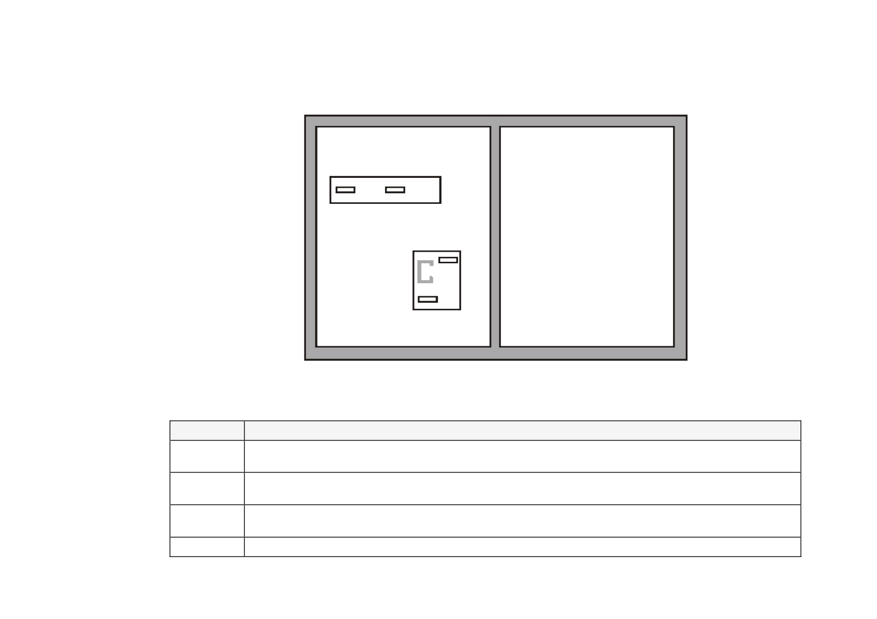
Test Points
The following test points are located on the control board and can be accessed through the Technology Option housing. When used with a meter, they
will provide valuable information in the event of a fault. Refer to Parker SSD Drives for further information.
IF
VA
Technology Box
IA
Option
0V
Test Points viewed through the front of the drive.
Test Point
Description
IF
Field current feedback
0.0V = 0% 4.0V =100% (mean voltage),
value of FIELD I FBK diagnostic, Tag No. 300
IA
Armature current feedback ± 1.1V ≡ ±100% (mean current),
value of CURRENT FEEDBACK diagnostic, Tag No. 298
VA
Armature volts feedback +5V ≡ +100%, +2.5V ≡ 0%, 0V ≡ -100% calculated VA (mean voltage),
value of TERMINAL VOLTS diagnostic, Tag No. 57
0V
Control board 0V reference
Chapter 8 Routine Maintenance and Repair
This chapter contains preventive maintenance procedures, contact details for repairing the unit, and instructions for replacing
fuses and fans.
Maintenance
• Disposal
• Service Procedures
• Technical Support Checks
• Repairs for Frames 4 & 5
Repair
• Repairs for Frame 6
• Saving Your Application Data
• Repairs for Frame H
• Returning the Unit to Parker SSD Drives

Routine Maintenance and Repair 8-1
Maintenance
Because of its solid state design, the DC590+ Digital drive has few items requiring service or maintenance. Service is typically a matter of replacing
fuses, checking electrical contacts, and isolating problems in the overall system application.
WARNING
Service procedures must be performed by qualified personnel with an understanding of the dangers inherent in high voltage applications and the
precautions necessary when servicing industrial equipment. The customer is responsible for assessing the technical competency of in-house service
personnel.
Service Procedures
Required Tools and Equipment
Tools needed for routine service operations include basic hand tools — screwdrivers, wrenches, etc.
WARNING
Only qualified service personnel should attempt to repair or replace parts in the 590+.
Isolate the entire 590+ drive from electrical power before attempting to work on it.
Preventive Maintenance
You should perform regular preventive maintenance every six months to ensure long life and continued usefulness of the 590+. Keep the drive and its
components clean, check auxiliary fans if fitted, and make sure connections and mounting bolts have not loosened from vibration.
The control and field wires can be checked by gently attempting pulling the wires out of the terminals. The terminals should hold the wires firmly in
place.
All the remaining wires should be checked with a torque wrench. Refer to Appendix E: "Technical Specifications" - Termination Tightening Torque
tables.

8-2 Routine Maintenance and Repair
Repair
There are no user-serviceable components. This section contains information for repair work that may be undertaken.
Saving Your Application Data
The Drive retains saved settings during power-down. You can download and upload this back into the repaired unit, if necessary. You may, depending
upon your knowledge of the fault, attempt the back-up of your application data now, refer to Chapter 6: “The Keypad” - Copying an Application.
If the fault clearly lies within the MMI, then return the unit for repair.
Returning the Unit to Parker SSD Drives
Before calling Parker SSD Drives Customer Service, make sure you have the following information available:
Information
Source
Model number and serial number
DC590+Digital drive rating label
Motor horsepower, armature current and voltage, field current and voltage, base and top
Motor nameplate
speed ratings
Speed voltage feedback per 1000 RPM (analog device), or counts per revolution(digital device)
Speed feedback device nameplate
Applications information and operating environment
System drawings.
Contact your nearest Parker SSD Drives Service Centre to arrange return of the item.
You will be given a Returned Material Authorisation. Use this as a reference on all paperwork you return with the faulty item.
Pack and despatch the item in the original packing materials; or at least an anti-static enclosure. Do not allow packaging chips to enter the unit.
Warranty Information
Warranty information precedes the Contents at the front of this manual.
Routine Maintenance and Repair 8-3
Disposal
This product contains materials which are consignable waste under the Special Waste Regulations 1996 which complies with the EC Hazardous Waste
Directive - Directive 91/689/EEC.
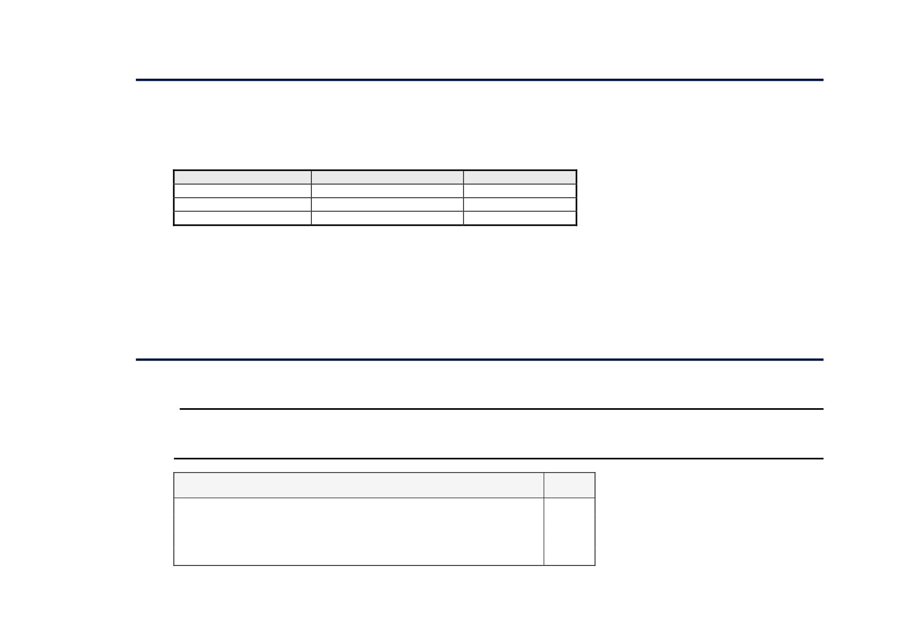
We recommend you dispose of the appropriate materials in accordance with the valid environmental control laws. The following table shows which
materials can be recycled and which have to be disposed of in a special way.
Material
Recycle
Disposal
metal
yes
no
plastics material
yes
no
printed circuit board
no
yes
The printed circuit board should be disposed of in one of two ways:
1. High temperature incineration (minimum temperature 1200°C) by an incinerator authorised under parts A or B of the Environmental Protection Act
2. Disposal in an engineered land fill site that is licensed to take aluminium electrolytic capacitors. Do not dispose of in a land fill site set aside for
domestic waste.
Packaging
During transport our products are protected by suitable packaging. This is entirely environmentally compatible and should be taken for central disposal
as secondary raw material.
Technical Support Checks
The results of the following checks will be very useful to Parker SSD Drives’ Technical Support.
WARNING
Please only attempt these checks if you are electrically competent.
9 or 8
Miscellaneous Checks
Check 24V present at Terminals C1 to C9 (C1 is 0V) - dc
Check ±10V present at Terminals B3 and B4 (B1 is 0V) - dc
Check auxiliary supply present at Neutral & Line, 110/240V ac
Check the fans rotate, where applicable

8-4 Routine Maintenance and Repair
WARNING
Now isolate the unit completely from all supplies. It may be necessary to remove an armature and field
connection to carry out the following checks.
Continuity Test on Fuses Using a Meter
9
or 8
Check the coding fuses on the power board
Check the auxiliary fuses etc. (fan fuse, if applicable)
Diode Check on Power Terminals Using a Meter
9
or 8
A+ to L1, L2, L3 and Earth Terminal = Open Circuit
A- to L1, L2, L3 and Earth Terminal = Open Circuit
Internal Field Check Using a Meter
9
or 8
All the coding fuses must be OK before continuing with the following checks since the fuses are in the circuit.
-ve to L1 & +ve to F+ = Diode Drop (approximately 0.5V)
-ve to L2 & +ve to F+ = Diode Drop (approximately 0.5V)
-ve to F- & +ve to F+ = Diode Drop (approximately 0.5V)
-ve to L1 & +ve to F- = Open Circuit
-ve to L2 & +ve to F- = Open Circuit
External Field Check Using a Meter
9
or 8
-ve to FL1 & +ve to F+ = Diode Drop (approximately 0.5V)
-ve to FL2 & +ve to F+ = Diode Drop (approximately 0.5V)
-ve to F- & +ve to F+ = Diode Drop (approximately 0.5V)
-ve to FL1 & +ve to F- = Open Circuit
-ve to FL2 & +ve to F- = Open Circuit
Make a note of the Serial Number and Model Number.
Serial Number
Model Number
Re-establish all connections. All terminals should be secure and not over-torqued.
Routine Maintenance and Repair 8-5
Repairs for Frames 4 & 5
Replacing the Fan (Frames 4 & 5)
WARNING!
Ensure that all wiring is
electrically isolated and cannot be
made “live” unintentionally by other
personnel.
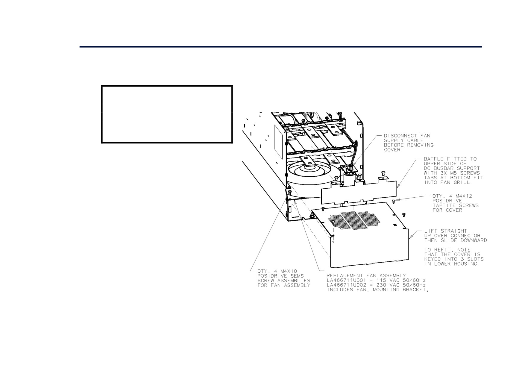
Remove the terminal cover. Unscrew the three
screws securing the baffle and remove. Disconnect
the fan supply cable. Remove the two M8
earth/ground screws on the back of the drive
(Frame 5). Remove the fan cover. Remove the fan
assembly and screws as detailed above.
Reverse the procedure for refitting the fan
assembly - refer to the refitting note in the diagram
above. The replacement fan assembly includes the
fan, cover and capacitor, requiring just a simple
connection of the supply cable.
Heatsink Cooling Fan
Connections
These fans are connected on the power board to the
cooling fan supplies, CONN 2 or 3 as described
below:
•
380, 500, 725, 830A models have a single fan
matched to the auxiliary supply and connected
to CONN 2.
1580A models have two fans matched to the
auxiliary supply connected to CONN 2 & 3.
8-6 Routine Maintenance and Repair
Repairs for Frame 6
WARNING!
The phase assembly metalwork (L1, L2 & L3) is LIVE when the unit is switched on. Isolate the entire DC590+
drive from electrical power before attempting to work on it.
Only qualified service personnel should attempt to repair or replace parts in the 590+.
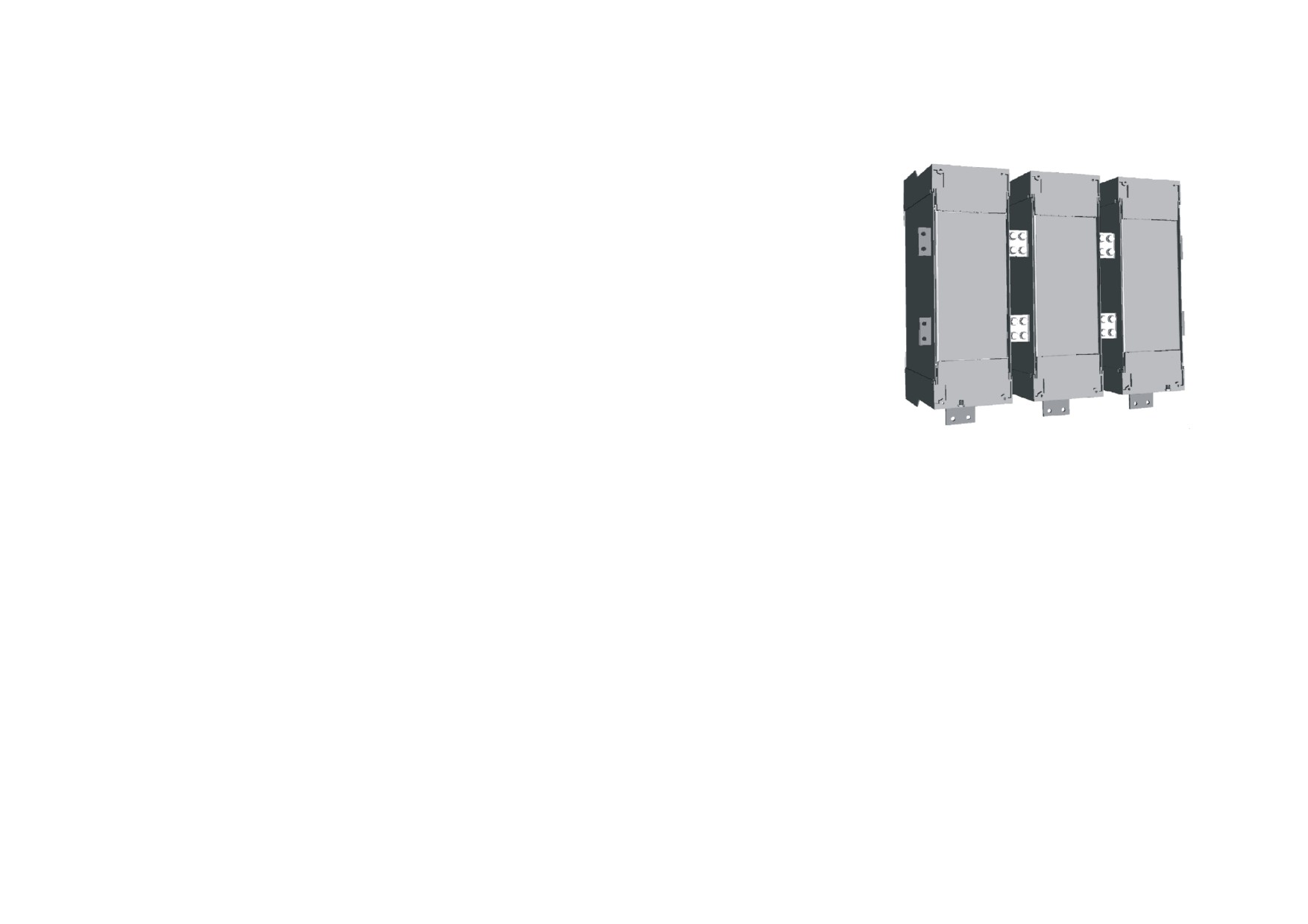
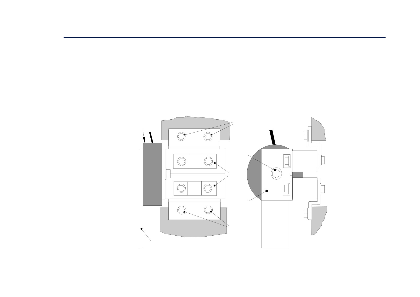
AC Fuse Replacement (Frame 6 Non-Regen Unit - 2Q)
The AC fuse can be replaced in-situ. With the front of the drive removed (the Control Panel Assembly), the replacement should take about 20 minutes.
Removing the Control Panel Assembly from the cubicle completely will make access easier, but requires the removal of all connections made to it. It
may be possible to support the Control Panel Assembly (11.25kg/25 lbs) and sling it away from the Phase Assemblies far enough to gain access.
Removal
1. Loosen the retaining screws in the Field Controller plug. Unplug all connections to the Door Assembly
(control connections) and the Field Controller (Auxiliary Plug and Field Plug).
2. Undo the fixings to remove the front cover from the Control Panel Assembly.
3. Disconnect the flying leads of the Control Panel Assembly from the three Phase Assemblies. Remove the
external earth connection(s) made to the Front Cover.
4. Remove the 12mm x M6 fixings in the four corners that secure the Control Panel Assembly. Loosen the
top and bottom central support screws (but do not remove) and lift the Control Panel Assembly away
from the three Phase Assemblies.
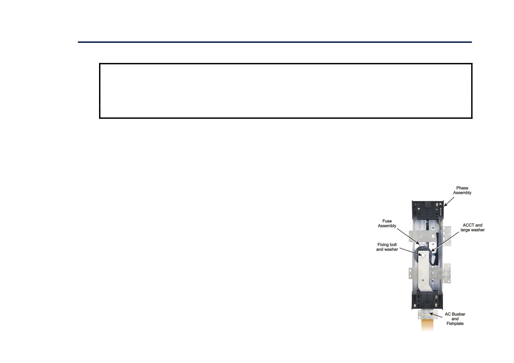
5. Remove the fixings that secure the failed Phase Assembly front cover.
6. Disconnect the fishplate connected to the AC Busbar.
7. Slowly remove the ACCT's fixing bolt and washer from the AC Busbar, supporting the ACCT and large
(rubber) washer as you do so. Lower the ACCT to one side and remove the rubber washer.
8. The fuse is mounted on a plate. Remove this Fuse Assembly from the Phase Assembly.
9. On the bench, undo the central bolt from the Fuse Assembly taking note of the placement of washers and
other parts.
Routine Maintenance and Repair 8-7
Refitting
1. Refit the Fuse to the mounting plate. Torque to 45Nm (33 ft.lbf). Fix the mounting plate to the Phase Assembly, securing it with the two bolts and
washers. Torque to 32Nm (23.6 ft.lbf).
2. Slide the AC Busbar into position in the Phase Assembly and secure the ACCT and large rubber washer with the central bolt and washer. Torque to
45Nm (33 ft.lbf).
3. Reconnect the AC Busbar's fishplate carrying the mains connection (L1, L2 or L3). Torque to 55Nm (40.6 ft.lbf).
4. Refit the Phase Assembly front panel and secure with four screws and washers.
5. Offer up the Control Panel Assembly to the three Phase Assemblies and hang on the central support screws. Secure with 12mm x M6 screws and
washers.
6. Reconnect the flying leads of the Control Panel Assembly to the three Phase Assembly units. Tighten the retaining screws in the Field Controller
plug. Refer to Chapter 3: "Installing the Drive" - Frame 6: Assembly and Installation - Terminals.
7. Refit the front cover to the Control Panel Assembly, securing with the screws and washers. Connect the external earth to the Front Panel.
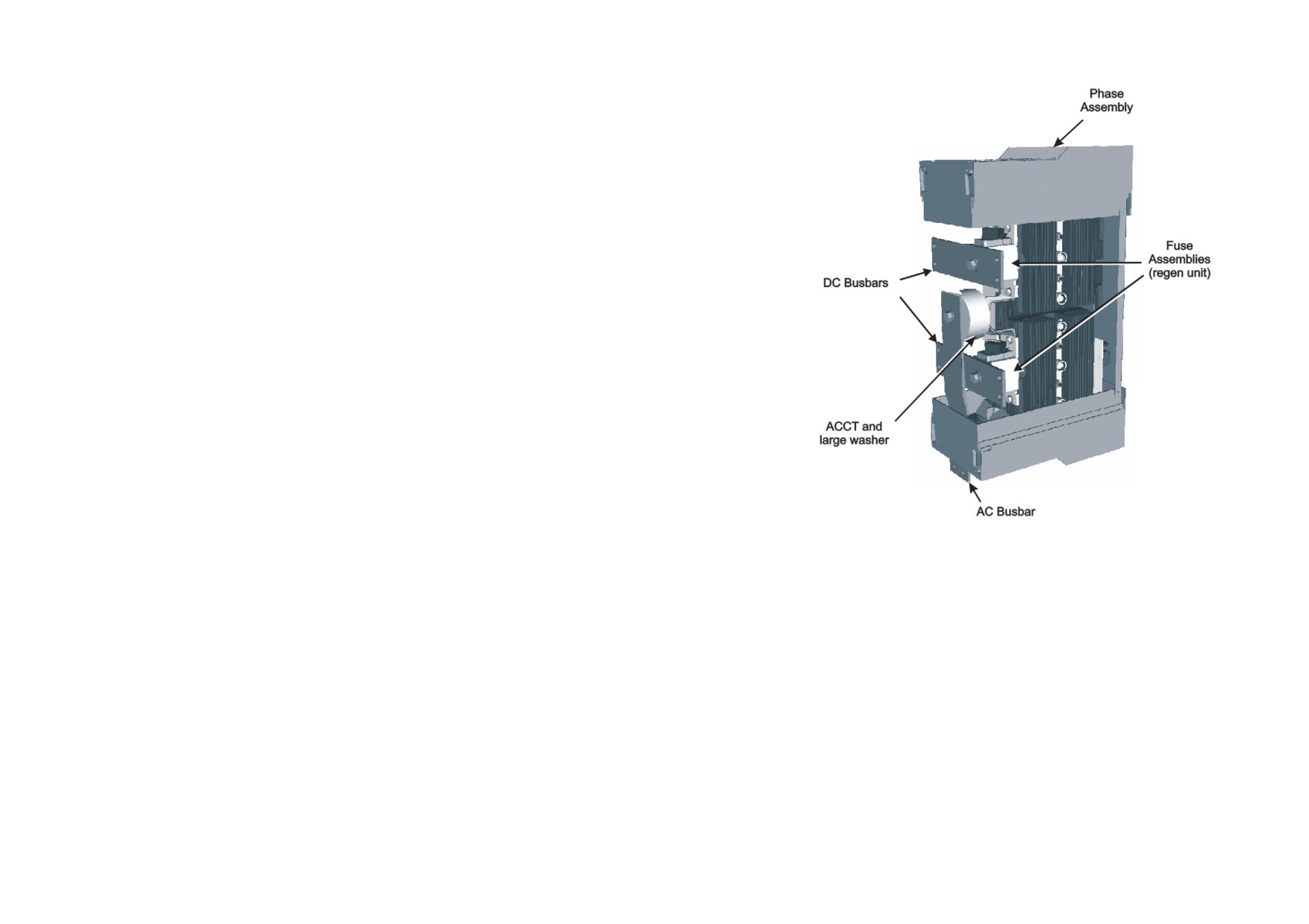
DC Fuse Replacement (Frame 6 Regen Unit - 4Q)
The DC fuse(s) can be replaced in-situ. With the front of the drive removed (the Control Panel Assembly), the replacement should take about 20
minutes. Removing the Control Panel Assembly from the cubicle completely will make access easier, but requires the removal of all connections made
to it. It may be possible to support the Control Panel Assembly (11.25kg/25 lbs) and sling it away from the Phase Assemblies far enough to gain
access.
Removal
1. Loosen the retaining screws in the Field Controller plug. Unplug all connections to the Door Assembly (control connections) and the Field
Controller (Auxiliary Plug and Field Plug).
2. Undo the fixings to remove the front cover from the Control Panel Assembly.
3. Disconnect the flying leads of the Control Panel Assembly from the three Phase Assemblies. Remove the external earth connection(s) made to the
Front Cover.
4. Remove the 12mm x M6 fixings in the four corners that secure the Control Panel Assembly. Loosen the top and bottom central support screws (but
do not remove) and lift the Control Panel Assembly away from the three Phase Assemblies.
8-8 Routine Maintenance and Repair
5. Remove the four screws that secure the failed Phase assembly front panel. Remove
the front panel.
6. Remove the bolts securing the fishplates to the DC Busbar nearest the failed fuse.
7. If the failed fuse is located underneath the AC busbar: slowly remove the ACCT's
fixing bolt and washer from the AC Busbar, supporting the ACCT and large
(rubber) washer as you do so. Remove the rubber washer and lower the ACCT to
one side.
8. Unplug the lead connected to the microswitch that is fitted to the side of the Fuse
Assembly.
9. The fuse is mounted on a plate. Remove the two bolts and washers that secure this
plate to the Phase Assembly and lift away the Fuse Assembly and DC Busbar.
10. On the bench, undo the central bolt from the Fuse Assembly taking note of the
placement of washers and other parts. Re-build the assembly with the new fuse.
Tighten the DC Busbar bolt to 45Nm (33 ft.lbf).
Refitting
1. Refit the Fuse to the Mounting Plate. Torque to 45Nm (33 ft.lbf). Fix the mounting
plate to the Phase Assembly, securing it with the two bolts and washers. Torque to 32Nm (23.6 ft.lbf).
2. Plug the lead back onto the microswitch (removed earlier).
3. Slide the AC busbar into in the Phase Assembly and secure with the bolt and washer. Torque to 45Nm (33 ft.lbf).
4. Refit the fishplates that connect to the DC Busbars. Torque to 55Nm (40.6 ft.lbf).
5. Offer up the Control Panel Assembly to the three Phase Assemblies and hang on the central support screws. Secure with 12mm x M6 screws and
washers.
6. Reconnect the flying leads of the Control Panel Assembly to the three Phase Assembly units. Tighten the retaining screws in the Field Controller
plug. Refer to Chapter 3: "Installing the Drive" - Frame 6: Assembly and Installation - Terminals.
7. Refit the front cover to the Control Panel Assembly, securing with the screws and washers. Connect the external earth to the Front Panel.
Routine Maintenance and Repair 8-9
Replacing a Phase Assembly (Frame 6)
NOTE
The Non-Regen Phase Assembly (2Q) weighs 28kg (62 lbs)
The Regen Phase Assembly (4Q) weighs 33kg (73 lbs)
With the front of the drive removed (the Control Panel Assembly), the replacement should take
about 20 minutes. Removing the Control Panel Assembly from the cubicle completely will make
access easier, but requires the removal of all connections made to it. It may be possible to support
the Control Panel Assembly (11.25kg/25 lbs) and sling it away from the Phase Units far enough to
gain access.
Removal
1. Remove the plugs for the control wiring, auxiliary supply and field connections (loosen the
screws to remove the field plug). Remove the Protective Earth connections (PE).
2. Undo the fixings to remove the front cover from the Control Panel Assembly.
3. Disconnect the flying leads of the Control Panel Assembly from the three Phase Assemblies.
4. Remove the 12mm x M6 fixings in the four corners that secure the Control Panel Assembly.
Loosen the top and bottom central support screws (but do not remove) and lift the Control Panel Assembly away from the three Phase Assemblies.
5. Remove the bolts securing the fishplates to the DC Busbars.
6. Fit an M10 x 20mm long "temporary hanging" bolt to the "temporary hanging" mounting hole (top-centre) of the phase assembly to be removed.
Screw it in loosely, leaving a few millimetres of thread still showing.
7. Remove the fixing bolts that hold the failed Phase Assembly onto the back panel. Lift it off the "temporary hanging" bolt. Refer to the note about
weights at the top of the page.
Refitting
1. Hang the new Phase assembly onto the "temporary hanging" bolt. The fans should be at the bottom of the unit. Fit the 4 off M10 bolts and torque to
32Nm (23.6 ft.lbf).
2. Remove the "temporary hanging" bolt.
3. Refit the fishplates to the DC Busbars. Torque to 55Nm (40.6 ft.lbf).
4. Refit the front panel and secure with four screws and washers.
5. Offer up the Control Panel Assembly to the three Phase Assemblies and hang on the central support screws. Secure with M6 x12mm long screws
and washers.
6. Reconnect the flying leads of the Control Panel Assembly to the three Phase Assembly units. Refer to Chapter 3: "Installing the Drive" - Frame 6:
Assembly and Installation - Terminals.
7. Refit the front cover to the Control Panel Assembly, securing with the screws and washers.
8. Connect the plugs for the control wiring, auxiliary supply and field connections (tighten the screws to secure the field plug). Remake the Protective
Earth connections (PE).
8-10 Routine Maintenance and Repair
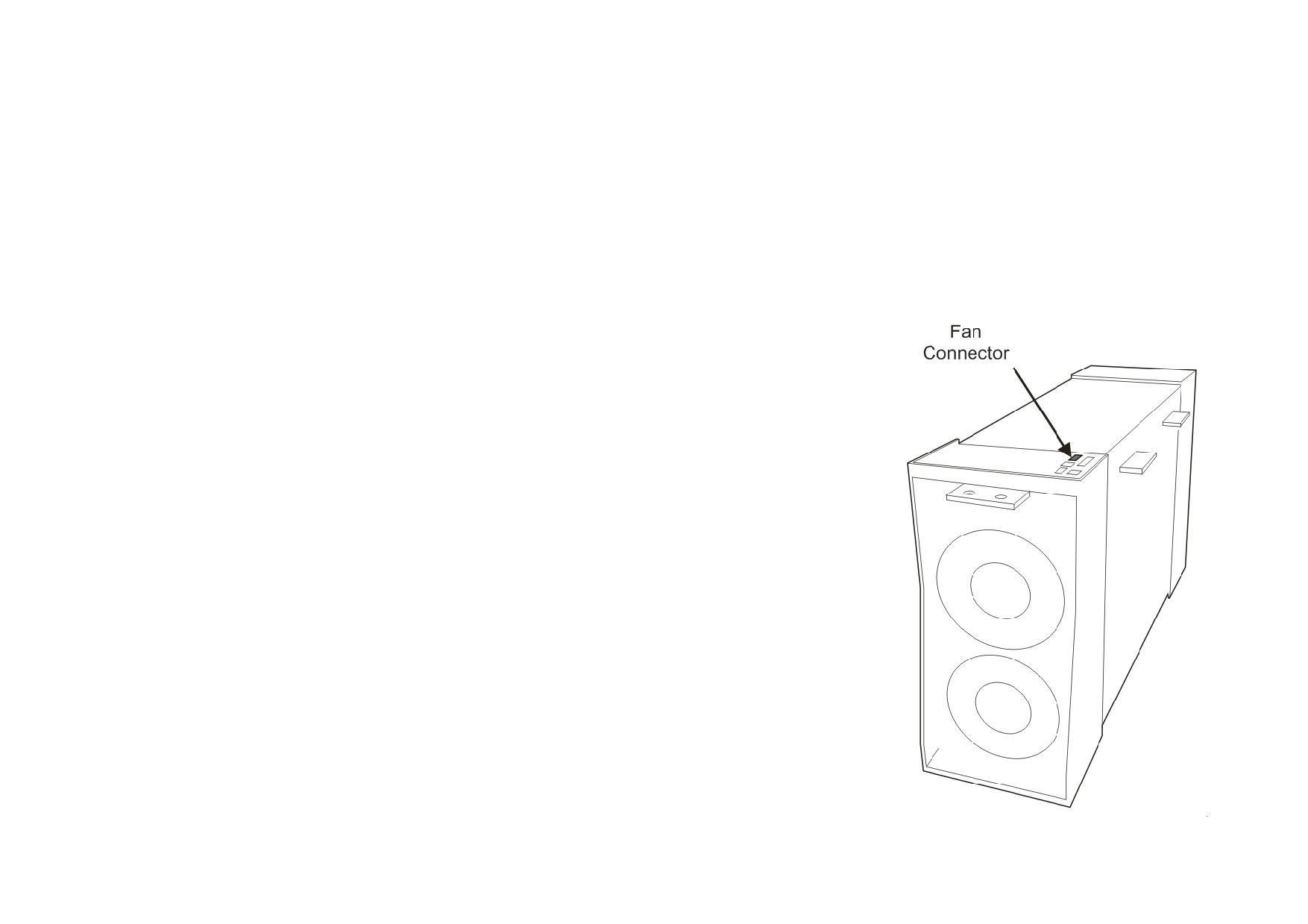
Replacing a Fan (Frame 6)
There are two fans mounted inside the base of each Phase Assembly. These are hard-wired together and are supplied as an assembly. Replacement of
both fans is easy and should take about 15 minutes.
Removal
1. Remove the four screws that hold the bottom fan grille in place.
2. Remove the two screws from each fan.
3. Trace the route of the fan cable back to the front of the phase assembly and remove the fan
connector from the phase assembly.
4. Remove the fans and cable assembly from phase assembly.
5. Fit the two fans to the phase assembly and secure with the screws. Hand-tighten.
6. Fit the new fan connector to the front of the phase assembly.
Routine Maintenance and Repair 8-11
Repairs for Frame H
Fuse Replacement (Frame H)
1. Remove the front cover.
2. Unplug the ribbon cables to the trigger boards.
3. Open the swing-frame using the two quick-release fixings at the right hand end.
590+ 4Q Product (Regenerative)
FRONT VIEW
SIDE VIEW
Phase Assembly
Current
Upper Phase Assembly
Connection Screws
Transformer
B
C
Screw
F
G
Fuse
Handles
A
H
I
Fuse
CT Plate
D
E
Phase Assembly
Lower Phase Assembly
Connection Screws
AC Incoming
Busbar
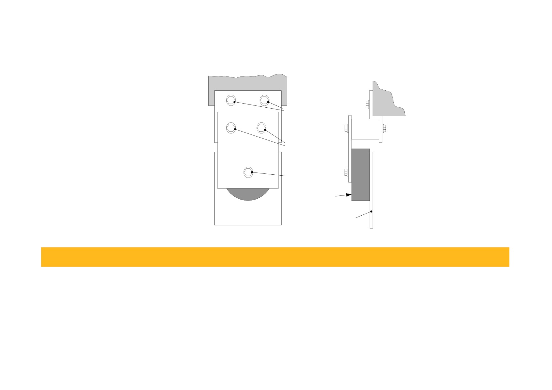
Figure 8-1 590+ (Frame H) Fuse Replacement Diagram
8-12 Routine Maintenance and Repair
IMPORTANT
When re-assembling the unit, apply a `zinc-loaded’ jointing compound between the fuses and busbars, and between the
busbars and phase assemblies (BICC BX1 - Parker SSD Part No. EA466241)
Observe all tightening torque levels, refer to Appendix E: “Technical Specifications” - Termination Tightening Torque (Frame H).
Bench-Top Replacement Procedure
1. Disconnect the relevant fuse microswitch assembly by unplugging the lead assembly from the rear trunking.
2. Remove the M12 (A).
3. Loosen (but do not remove) the four M10 screws (B, C, D, E).
4. Hold the fuse assembly handle in one hand and remove the two screws (D, E) from the lower phase assembly.
CAUTION: The fuse assembly weighs 9kg maximum.
5. Hold the fuse assembly handles and remove the two screws (B, C) from the upper phase assembly.
6. With the fuse assembly on the bench, remove the M12 screws (F, G, H, I) holding the fuses to the busbars. Take a note of the fuse microswitch
position on the fuse assembly, do not forget, as the lead assembly will not fit if mounted in the wrong position.
Reverse the above procedure for replacement. Remember to re-connect the fuse microswitches.
In-Situ Replacement Procedure
1. Disconnect the relevant fuse microswitch assembly by unplugging the lead assembly from the rear trunking.
2. Remove the M12 screw (A), and the 4 screws (F, G, H, I). Remove the CT plate and handles.
3. Remove the relevant screws (B, C or D, E) and lift the fuse busbar assembly from the phase assembly.
4. Replace the fuse on the busbar and re-connect the microswitch. Fully tighten the fuse to the busbar.
5. Fit the fuse busbar assembly on to the phase assembly. Don’t fully tighten the screws yet.
6. Position the CT plate on top of the fuses. The slack in the fuse busbar assembly will allow the fixing holes to be aligned. Insert the screws.
7. Fully tighten all screws (including those in 5 above).
8. Re-connect the fuse microswitches.
Routine Maintenance and Repair 8-13
591+ 2Q Product (Non-Regenerative)
FRONT VIEW
SIDE VIEW
Phase Assembly
D
E
Fuse Assy/Phase Assy
Fixing Screws
B
C
Fuse
CT Plate/Fuse
Fixing Screws
A
CT Plate/CT Boss
Fixing Screw
Current
Transformer
AC Incoming
Busbar
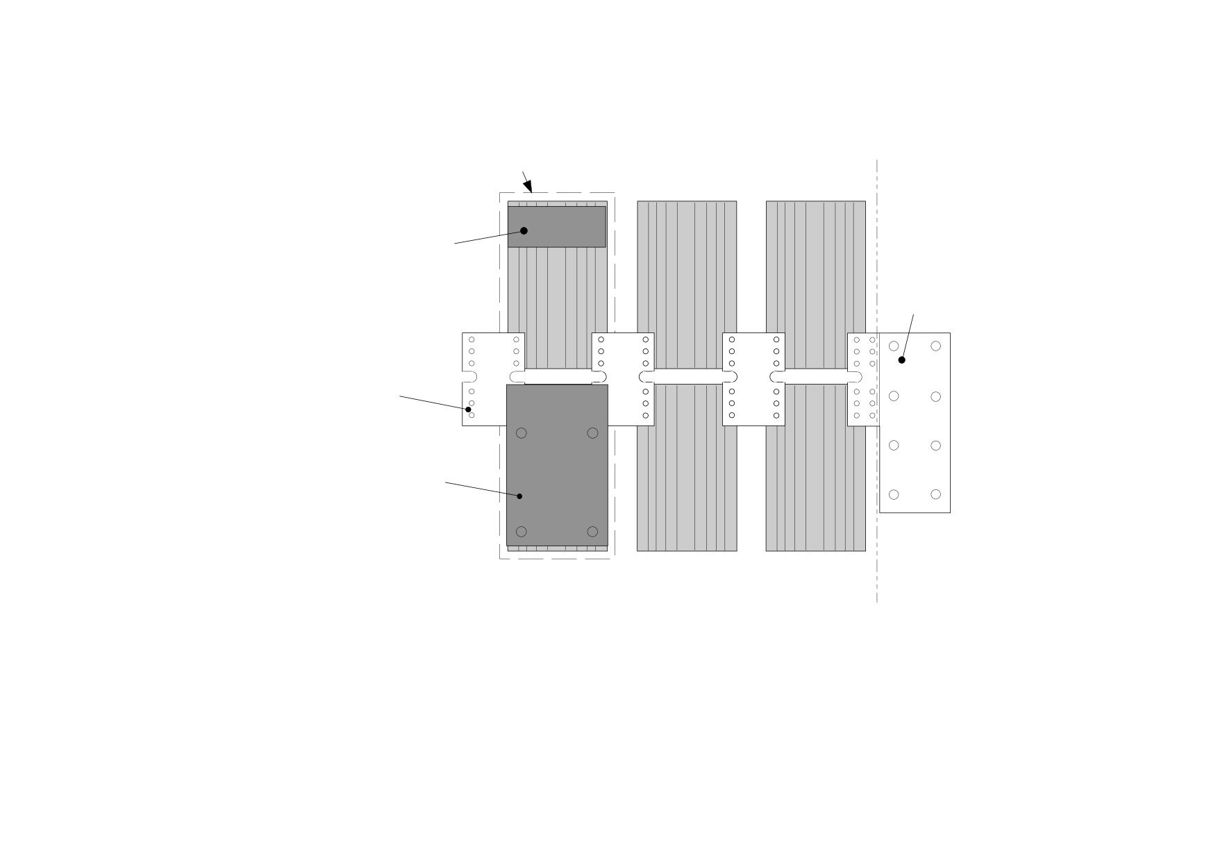
Figure 8-2 591+ Fuse Replacement Diagram
IMPORTANT
When re-assembling the unit, apply a `zinc-loaded’ jointing compound between the fuses and busbars, and between the
busbars and phase assemblies (BICC BX1 - Parker SSD Part No. EA466241)
Observe all tightening torque levels, refer to Appendix E: “Technical Specifications” - Termination Tightening Torque (Frame H).
Bench-Top Replacement Procedure
Working on the relevant fuse assemblies:
1. Remove the M12 screw (A).
2. Release the two M12 screws (B, C) and remove the CT plate.
3. Remove the two M10 screws (D, E) fixing the fuse assembly to the phase assembly.
4. On the bench, replace the relevant fuse on the fuse assembly.
5. Reverse the procedure for re-fitting.
8-14 Routine Maintenance and Repair
Phase Assembly Replacement (Frame H)
Phase Assembly
Dummy Board
(one only shown
for clarity)
Busbar
Stack of
interconnecting
plates
A-
Trigger Board
(one only shown
for clarity)
4Q
(upper phase assemblies only shown)