Kobelco SK160LC-6E, ED190-6E, SK210LC-6E, SK250LC-6E, SK290LC-6E, SK330LC-6E Excavator. Brief instruction - page 3
SWING SAFETY / USE SWING FLASHERS BUILD BANKING FOR SLOPE OPERATION
Page 2-8Dynamic Acera 01/02
SAFETY
PRECAUTIONS
G. WORKING AROUND UTILITIES
If it is suspected that utility lines such as, gas, wa
ter, phone or electrical power are in the work
area, contact the local utility authority for line
location BEFORE beginning work in the area.Use
extreme caution around electrical power lines.
Keep a suffi cient distance away from electrical
lines during op eration. See chart below for
minimum distances.
(FEET) 3.0M (10)OR
MORE
LINE VOLTAGE 0 ~50,000
50,000 ~200,000 200,000
~350,000 350,000
4.5M (15)OR MORE
~500,000 500,000
6.0M (20)OR MORE
~750,000 750,000
7.5M (25)OR MORE
~1,000,000
10.5M (35)OR MORE
13.5M (45)OR MORE
H. LIFTING
MINIMUM DISTANCE-M
much deeper than expected.The machine can
easily become buried under such conditions.Use
extreme caution while operating the machine
This machine is an excavator.Use extreme
around or in snow.
caution when lifting or moving heavy loads.Use
proper lifting equipment rated at a capacity to
handle the load. NEVER USE BUCKET TEETH
J. FILLED OR UNSTABLE GROUND
TO LIFT OR MOVE HEAVY LOADS.
Be certain the condition of the work site is stable
and capable of supporting the machine during
operation. Do not operate attachment too close to
I. FROZEN & SNOW COVERED WORK SITES Use
the machine. Operation of the machine on shoul
extreme caution when operating the machine on
ders or filled areas could cause the machine to
frozen or snow covered work sites.Operate all
be come unstable presenting a work
controls slowly and cautiously to prevent sudden
hazard.Position the travel motors to the rear of
movements that may cause the machine to unex
the machine, allow ing for quick reversal, should
pectedly shift, slide or move.Even on the slightest
the work area become un stable.
slope, when snow is present or work area is
KEEP A SAFE DISTANCE FROM UTILITIES
frozen can allow a machine to unexpectedly
move. Snow on shoulders or snow drifts can be
USE PROPER LIFTING DEVICES
SK32001006
USE EXTREME CAUTION ON FROZEN OR SNOW
SK32001022
WORK ON STABLE GROUND
SK32001021
Page 2-9Dynamic Acera 01/02
SAFETY PRECAUTIONS
K. RESTRICTED WORK AREAS
In work sites with limited height and swing areas
such as tunnels,bridges,around electrical power lines,
other utilities,or inside structures,use extreme cau
tion in keeping the machine and its attachment a
safe distance away to prevent personal injury and /
or equipment or structure damage.Use a flagman to
direct the operator.
L. PARKING THE MACHINE
Always park the machine on a firm,level surface. If
no firm level surface is available,block the tracks and
lower attachment to the ground to help prevent
the supervisor and all operators that the machine
ma chine movement. Should the machine be
is under inspection or maintenance and they will
parked on a roadway, move the machine to the
be informed when the machine is ready for
shoulder to al low passing of traffic. Also post
normal op eration.
reflective warning signs and markers at a
distance from the machine to safely warn
motorists. Refer to local code and regulations
B. TOOLS &EQUIPMENT
regarding the posting of work area warn ings and
Use the proper tools and equipment for the task
markers.
at hand. Know the proper use of the tools and
equip ment before starting any inspection or
maintenance procedures.
M. STABILIZE ATTACHMENTS
Stabilize all attachments removed from the
machine to prevent the attachment falling over.
C. PERSONAL EQUIPMENT
Wear well fitting work clothes,hard hat,safety
1.5 INSPECTION &MAINTENANCE
shoes and gloves. Confine long hair,loose
SAFETY A. “TAG-OUT ” MACHINE
clothing and re move all jewelry before attempting
Before performing any inspection or maintenance
any inspection or maintenance procedures to this
procedures to the machine,fill out and post to the
machine or attach ments.
operators controls a “DO NOT OPERATE ” tag to
BE AWARE OF OBSTACLES
warn persons not to start the machine.Also inform
STABILIZE ATTACHMENTS WHEN REMOVED
SK32001026
USE PROPER TOOLS
PARKING SAFETY
SK32001025
Page 2-10Dynamic Acera 01/02
SAFETY PRECAUTIONS
D. STOP THE ENGINE
BE CERTAIN TO TURN ENGINE OFF AND LACE THE SAFETY LOCK LEVER IN THE “LOCKED”
(UP) POSITION before attempting any inspection or maintenance procedures to the machine. Failure to
stop engine could result in serous bodily injury or death.
E. SET THE ATTACHMENT
Always set the machine in the hydraulic oil check position on firm level ground before attempting any in
spection or maintenance procedures to the ma chine. If it is not possible to put the machine in this
position, secure the boom, arm and attacment to help prevent sudden movement. ALWAYS PLACE AT
TACHMENTS ON THE GROUND AND RAISE THE SAFETY LOCK LEVER BEFORE LEAVING THE
CAB.
F. CLEAN THE MACHINE
Keep the machine clean and free of debris, excess or spilled lubricants, fuel and fluids. Use aproved sol
vents, detergents and water to clean the machine and its components on a regular basis. Be careful not
to allow water to reach electrical components. Serious damage can occur to the electrical system by
allowing water to reach the electrical components. Never clean inside of cab, or electrical components
with pressurized water or steam.
G. PRESSURIZED FLUIDS & LUBRICANTS Always release pressure from hydraulic reservoir, engine
coolant, fuel system and all systems cotaining pressure before removing any caps or components BE
CAUTIOUS OF HOT FLUIDS AND GASSES FROM SYSTEMS ON MACHINES THAT HAVE JUST
BEEN STOPPED. ALLOW SUFFICIENT TIME FOR SYSTEMS TO COOL BEFORE PER FORMING
ANY INSPECTION OR MAINTENANCE PROCEDURES.
H. SUPPORT THE MACHINE
If it becomes necessary to raise the machine for inspection or maintenance, always support the ma chine
by positioning the machine as shown in the illustration and use safety supports or blocks, with a sufficient
capacity rating to support the machine, under the tracks. NEVER INSPECT OR PERFORM
MAINTENANCE PROCEDURES UNDER A RAISED MACHINE THAT IS NOT SUFFICIENTLY SUP
PORTED.
STOP ENGINE/ENGAGE SAFETY LOCK LEVER HYDRAULIC OIL CHECK POSITION
KEEP MACHINE CLEAN
RELEASE HYDRAULIC TANK PRESSURE SUPPORT THE MACHINE
Page 2-11Dynamic Acera 01/02
SAFETY PRECAUTIONS
I. REFUELING
Move the machine to a well ventilated area for
pressure.When inspect ing for leaks, use a small
refuel ing. Use only specified fuel as described in
piece of cardboard, wood or metal to locate
the MAIN TENANCE section of this operators
leaks.SMALL
(PINHOLE) LEAKS CAN BE
manual. Imme diately clean up all spilled fuel and
DANGEROUS IF CONTACT WITH SKIN OR
dispose of prop erly. After refueling is complete,
EYES IS MADE.Wear approved safety glasses or
securely tighten fuel cap.
face shield,gloves, hard hat, safety shoes and
work clothes during all inspection and
maintenance pro - cedures.
J. HYDRAULIC PRESSURE
Under normal conditions,all circuits of the
hydraulic
system
are
under extreme
K. TRACK SHOE TENSION
The grease used to adjust the track shoe tension
is under extreme pressure in the cylinder.Use
ex-treme caution when adjusting track shoe
tension. KEEP FACE,HANDS AND LEGS AWAY
FROM THE GREASE NIPPLE AREA. Carefully
and slowly loosen the grease nipple when
lessening track shoe ten sion. Never loosen
grease nipple more than one com plete turn.
L. ELECTRICAL SYSTEM
SK32001034
Before performing any inspection or maintenance
USE CAUTION WHEN ADJUSTING TRACKS
to the electrical system,or performing any welding
pro cedures, disconnect the negative(-)cables
from the battery terminals.Not disconnecting the
negative (-) cable could cause extensive damage
to the electri cal system.
DISCONNECT BATTERY
NEGATIVE (-) CABLE WHEN
INSPECTING ELECTRICAL
OR WELDING
M. USE APPROVED WORK LIGHTS
Use only approved work lights when performing
in spection and maintenance procedures to
prevent pos sible fire or explosion.Certain types
SK32001035
of work lights should not be used due to the
possibility of ignition of certain flammable gasses
ELECTRICAL SYSTEM PRECAUTION
and fluids from the ma chine.
N. DISPOSE OF WASTE PROPERLY
Dispose of oils,fuel,coolant,solvents, filters, batter
- ies etc. according to federal,state and local
codes and regulations regarding hazardous
waste disposal. Contact Local authorities for
proper disposal meth ods of such materials.
SK32001036
USE PROPER LIGHTING
REFUELING
CHECKING FOR HIGH PRESSURE LEAKS
Page 2-12Dynamic Acera 01/02
SAFETY PRECAUTIONS
1.6 BATTERY SAFETY
A. WEAR PROPER PROTECTIVE CLOTHES Wear
around batteries.Battery electrolyte (acid)ill cause
long sleeve shirt,gloves and approved safety
severe burns if allowed to make contact the
glasses or face shield when working with or
clothing, skin or eyes. Should electrolyte (acid)
come in contact with clothes, skin or
eyes,immediately remove ef fected clothing, flush
area with clean water for 15 minutes and get
prompt medical attention.
B. KEEP AWAY FROM FIRE OR FLAMES Never
allow batteries in the vicinity of fire or flames and
do not smoke when working with batteries. Ex
plosive hydrogen gas is produced by the
SK32001038
electrolyte (acid) in the batteries.Always work
KEEP AWAY FROM FIRE OR FLAMES
with batteries in a well ventilated area.
C. CHARGING BATTERY
Charge battery off of and away from machine in a
well ventilated area. When charging battery,
remove cell covers to allow gasses to escape.
Avoid breath ing gasses from battery.Wear
approved Safety equip ment when working with
batteries.
D. USING BOOSTER CABLES
Wear proper safety equipment when working with
batteries.
If using another machine or vehicle to boost
batter ies, make certain the machine or vehicle
MAKE CERTAIN OF THE POSITIVE (+)
DOES NOT touch the disabled machine.
AND NEGATIVE (-) TERMINALS
Make certain of the positive (+) and negative (-)
! WARNING
ter minals on the booster battery and the disabled
ma chine before connecting booster cables.
Improper booster cable connections can cause
an explosion resulting in personal injury.
Connect the positive (+) cable first,then connect
Connect booster cables using following proce
nega tive (-).
dure.
1. Connect booster cable to positive (+)
When disconnecting,disconnect the negative (-)
battery terminal of discharge battery.
cable first, then disconnect the positive (+) cable.
Connect other end of booster cable to
Refer to BASIC MACHINE OPERATION Section
positive battery ter minal of normal battery.
of this manual for proper procedures for use of
2. Connect other booster cable to negative (-)
booster cables.
battery terminal of normal battery. Connect
other end of booster cable to upper frame
of troubled machine.
3. Start engine and remove booster cables on
reverse order.
SK32001037
WEAR PROTECTIVE CLOTHES
Dynamic Acera 01/02
Page 2-13
SAFETY PRECAUTIONS
decals along with their locations.
1.7 WARNING LABELS & DECALS
Warning labels and decals are affixed to the machine
to remind operators and personnel specific safety pre
-
cautions in certain areas of the machine. The follow
1. SWING DANGER
ing are illustrated examples of all warning labels and
Located on each side of the rear counterweight. Part
Number - YN20T01003P2 (2REQ’D)
Located on top of engine fan shroud. Part
Number- YN20T01009P1
4. STOP ENGINE- WARNING
DANGE
R!
Depress stem or remove
KEEP CLEAR OF
cap slowly with
engine off to relieve
SWING AREA
Hydraulic Tank pressure.
YN20T01289P1
3. BATTERY - DANGER /POISON
2. PRESSURIZED HOT OIL - WARNING
Located on Battery89P1
Located on top of Hydraulic Tank. Part
Number - YN20T01289P1289P1
WARNING
5. BOOSTER CABLE- WARNING
Located on battery box
compartment. Part Number-
YN20T01015P2
Pressurized hot oil can
cause burns.
Page 2-14Dynamic Acera 01/02
SAFETY PRECAUTIONS
6. ACCUMULATOR CONTAINS
PRESSURIZED GAS- WARNING
Located on side of nitrogen accumulator
DANGER
Part Number- YN20T01216P1
WARNING
ACCUMULATOR CONTAINS PRESSURIZED GAS.
8. POWER BOOST SWITCH- WARNING
• Do not disassemble.
Located inside cab on R.H. Window.
• Do not remove plug in service.
Part Number- YN20T01004P1
• Do not dispose without relieving gas
loosening plug.
YN20T01216P1
! WARNING
Releasing power boost switch while lifting
7. BOOSTER CABLE - WARNING
a load can cause unexpected lowering of
Located on battery box access
load, resulting severe injury of death.
compartment. Part Number -
Never use power boost switch of lifting a
YN20T01338P1
load.
9. HEAVY LIFT SWITCH- WARNING
Located inside cab on R.H. Window.
Part Number- YN20T01340P1
10. ELECTRICAL POWER LINES-
WARNING Located inside cab on R.H. Panel.
Part Number- YN20T01006P1
12. DO NOT STEP ON - WARNING
Located on top of engine cover.
Part Number- 2432P3055
11. DO NOT LIFT MACHINE THROUGH
COUNTERWEIGHT LIFTING EYES -
DANGER Located on top of counterweight. (2
Required) Part Number- YN20T01221P1
Page 2-15Dynamic Acera 01/02
17. GREASE SWING BEARING
13. HOT COOLANT - WARNING
SAFETY PRECAUTIONS
opening radiator cap:
Located on top of engine fan shroud.
Part Number- YN20T01010P1
• Cool Down engine completely.
• Cover radiator with cloth rag.
• Loosen cap slowly to reliever pressure.
WARNING
YN20T01010P
1
Steam of hot coolant can cause injury or
blindness.
14. HOT PARTS - CAUTION
Never loosen or open radiator cap when
Located on top of engine cover.
coolant is hot and under pressure. Before
Part Number- YN20T01220P1
Located on back side of radiator compartment
door. Part Number- YN20T01097P1
CAUTION
Engine may be hot
which could cause
burns.
Do not touch engine
19. HYDRAULIC OIL CHECK POSITION
until it cools down.
Located on back side of pump compartment
YN20T01220P1
door. Part Number- 2432P3379
15. ROTATING PARTS - CAUTION
Located on top of engine cover
Part Number- YN20T01012P1
CAUTION
Rotating engine fan, hot engine parts
and drive belt can cause severe injury.
Do not open engine cover with engine
20. HYDRAULIC OIL USED
running.
Located on the back side of hydraulic
YN20T01012P1
tank. Part Number- 2432T6573
16. USE DIESEL FUEL
Located on side of fuel tank opening.
Part Number- YN20T01213P1
Located on upper frame lower right corner -
Below cab. Part Number- 2432P2689
21. SERIAL NUMBER PLATE
Located on upper frame lower right corner -
Below cab. Part Number- 2432T5613
18. ANTIFREEZE SOLUTION
Page 2-16Dynamic Acera 01/02
SAFETY PRECAUTIONS
22. KPSS &SWING BRAKE RELEASE -
CAUTION
CAUTION Located inside cab rear panel cover.
Part Number -YN20T01237P1
The KPSS work mode releases switch and
swing parking brake release switch are installed
on the rear side this cover.
Swing parking brake release switch
KPSS work mode release switch
26. BUCKET CAB INTERFERENCE
Bucket can contact and
-CAUTION Located inside cab,on right
damage cab when machine
indow glass lower corner.
Part Number - 2432P3380
CAUTION
• While operating swing action when the
• When the CPU error is displayed on the
parking brake can not be released set the
multidisplay, set the toggle swith to
toggle switch to “RELEASE “ position, and
“RELEASE “ position and contact our
CAUTION FOR
INTERFERE
Check clearance between
the parking brake si released. Usu ally, this
service department immediately.
toggle switch should be sent to norma
equipped with some
bucket and cab before
position and contact our service department
attachments.
immediately.
YN20T01010P1
operation. Exercise care
23. LIFTING FUEL TANK - WARNING
when operation a bucket near
Located on top of fuel tank.
cab.
Part Number -YN20T01028P1
YN20T01012P1
WARNING
Lift eyes or tank can fail when
lifting tank containing fluids and
27. READ OPERATOR MANUAL -WARNING
cause possible personal injury.
Located inside cab,on right indow glass
lower corner.
Drain all fluids from tank before
Part Number -YN20T01016P1
lifting.
YN20T01028P1
24. KEEP SURFACE CLEAN - WARNING
WARNING
Located on top of fuel tank (front left
corner). Part Number - 2432T6111
Read and understand the operators manual
before
operating
or
performing
maintenance on this machine.
WARNING
Failure to follow or pay attention to instruc
tions in operators manual can result in
injury or death.
It is your responsibility to be aware of and
follow all local laws and regulations. Before
starting machine, make sure hydrau lic
When servicing or repairing machine, keep sur
control lever is in lockout position and all
faces free of oil, water, grease, tools, etc. to
control levers are in neutral.
avoid possible slipping and / or falling from
machine,
which can cause personal injury. Sound horn to alert people.
obstacles are clear
2432T6111
Ensure bystanders and
25. BREAK GLASS IN CASE OF
Before leaving operators compartment,
EMERGENCY Located inside cab,on back
park on level ground, lower attachments to
window glass. Part Number
ground, make sure hydraulic control lever
-YN20T01178P1
is in lockout position and stop engine.
of machine before moving machine or its at
YN20T01016P1
tachments.
Do not carry riders or machine.
Page 2-17Dynamic Acera 01/02
SAFETY PRECAUTIONS
Located inside cab,on right window glass
28. DO NOT INSTALL ANY OBJECT ON THE
lower corner.Part Number - 2432T6109
HAND RAIL - WARNING
31. SAFETY LOCK LEVER - WARNING Located
on right side of operator’s right console. Part
WARNING
Number - PY20T01073P1
DO NOT INSTALL ANY OBJECT ON THE HANDRAIL
WARNING
This can cause the welds that fasten the
handrail to the operator’s cab to fatigue
Machine may move suddenly and cause
and crack to excessive vibration during
serious personal injury if a control lever is
machine operation.
accidentally touched be sure the safety lever is
disengaged and in the locked position before
Injury to the operator may result if he falls
exiting the cab. PY20T01073P1
to ground because of the unexpected
brakage of the welds.
2432T6109
32. DO NOT PINCH YOUR HAND(S)- CAUTION
Located left side of left console and on floor
29. NIBBLER &BREAKER OPERATION -
-left side of left console.
CAUTION Located on Left Hand operator
Part Number -YN20T01339P1 (2Req’d)
console.(OPT) Part Number -YT20T01054P1
PY20T01073P1
CAUTION
CAUTION
Do not set this switch to nibbler combined
Be careful not to pinch
flow operation position when using breaker.
your hand(s) when
operating the lever.
YY20T01039P1
30. NIBBLER &BREAKER SELECTOR
YN20T01339P1
VALVE - CAUTION
Located inside cab,on right window glass
33. KEEP CLEAR OF MACHINE -
lower corner (OPT).
DANGER Located on both sides of the arm
Part Number -YY20T01039P1
Part Number -YN20T01337P1 (2
required) YT20T01054P1ION
CAUTION
Procedure to change selector valve:
MARK SELECTION N Nibbler
B Breaker
E Extra
Please adjust suitable notch to capscrew.
CAUTION
(Some mark may not be indicated)
Falling front window can cause
injury. Always lock securely in
MarksCapscrew
Regular: Every 250 hours YY20T01039P1
MAINTENANCE
place with lock pins on both sides.
(When using nibbler or breaker) Contamination
34. FALLING FRONT WINDOW
and deterioration of hydraulic oil may
-CAUTION Located on upper frame
develop malfunctioning of control valves,
early wear, and seizure of hydraulic pumps,
of front window
and conse quential damage of entire
Part Number - LE20T01019P1
hydraulic circuit.
Replace filters and hydraulic oil, referring to
the following table:
1.- Hydraulic oil change: every 600 hours.
2.- Hydraulic return filter change:
First: 50 hours
Second: 250 hours
LE20T01019P1
Page 2-18Dynamic Acera 01/02
SAFETY PRECAUTIONS
35. TWO SPEED TRAVEL -WARNING
Located inside cab,on right window glass
lower corner Part Number - LE20T01019P1
WARNING
Automatic two speed travel system changes
travel speed automatically and can adversely
affect machine control when descending a
slope and loading or unloading on a trailer.
Personal injury can occur from sudden change
in machine control.
38. HYDRAULIC WARM UP -CAUTION
Put travel speed select switch in low speed
Located inside cab right window
position when descending a slope and loading
glass.
or unloading on a trailer.
Part Number -YN20T01263P1
LE20T01019P1
CAUTION
Slow or unexpected movement of the hydraulic
functions may result when the hydraulic oil is
cold.
Always perform the hydraulic oil warm up
procedure before attempting normal machine
operations.
Always keep personnel away from the area
around the machine during the warm up
36. STOP AND READ OPERATORS MANUAL
procedure.
BE FORE USING -WARNING
Located inside cab,on right side wall,behind the
YN20T012663P1
right control console (For manual throttle
control). Part Number -YN20T01319P1
37. OPERATOR’S CONTROL
PATTERN Located inside of cab door
Part Number -YT20T01072P1
38. HYDRAULIC WARM UP -CAUTION
Located inside cab right window
can result in overheatting and a shortened
glass.
engine life.
Part Number -YN20T01263P1
Before stopping engine, run at low idle for at
least 5 minutes to allow engine and turbo
charger to gradally cool down.
NOTICE
YN20T01007P1
Stopping engine without allowing it to cool
Page 2-19Dynamic Acera 01/02
SAFETY PRECAUTIONS
CALIFORNIA Proposition 65
Diesel engine exhaust and some of its con
39. CONTROL LEVER LOCK AND
stituents are known to the State of Califor
UNLOCK Located inside cab on left
nia to cause cancer, birth defects, and
control console. Part Number
other reproductive harm.
-YN20T01341P1
2432T6457
42.NOTICE FOR STOPPING ENGINE -
NOTICE Located inside cab,on right window
glass. Part Number - YN20T01007P1
NOTICE
Stopping engine without allowing it to cool
can result in overheatting and a shortened
engine life.
40. ELECTRICAL POWER LINES -
Before stopping engine, run at low idle for at
WARNING Located inside cab right window
least 5 minutes to allow engine and turbo
glass. Part Number -YN20T01007P1
charger to gradally cool down.
41.CALIFORNIA PROPOSITION 65 -
YN20T01007P1
WARNING Located inside cab,on right window
glass. Part Number - 2432T6457
WARNING
Page 2-20Dynamic Acera 01/02
SAFETY PRECAUTIONS
42. HANDLING PILOT HOSES WARNING
WARNING
-CAU
TION
UNDER EXTREME PRESSURE AND CAN PEN
Located on front panel inside the air cleaner
com partment.
ETRATE SKIN CAUSING SEVERE INJURY. KEEP
Part Number -YN20T01290P1
FACE AND BODY AWAY FROM GREASE FITTING
AREA. NEVER LOOSEN GREASE FITTING MORE
THAN ONE (1) COMPLETE TURN. IF GREASE
CAUTION
DOES NOT RELEASE AFTER ONE TURN OF THE
FITTING,
PILOT VALVE SIDE CONTROL VALVE SIDE 1.BUCKET (H)
GREASE IN TRACK TENSIONING MECHANISM IS
1
CALL AN AUTHORIZED
2 3 4 5 6 7
USE CAUTION WHEN
2.BUCKET (R) 3.BOOM (H) 4.BOOM (R)
KOBELCO SERVICE DEALER
5.SWING (LH) 6.SWING (RH) 7.ARM (H)
ADJUSTING TRACKS
FOR ASSISTANCE.
8.ARM (R)
8TORQUE GREASE FITTING TO
• HYDRAULIC OIL CAN BE HOT AFTER MACHINE
PERATION. ALLOW OIL TO COOL BEFORE STARTING
MAINTENANCE WORK.
WARNING
• BEFORE DISCONNECTING THE HYDRAULIC
HOSES..LOOSEN THE AIR BREATHER ON THE
HYDRAULIC OIL TANK AND BLEED OFF THE REMAINING
PRESSURE LEFT IN THE HY DRAULIC SYSTEM.
• CONTROL PATTERN FUNCTIONS MUST CORRESPOND
TO BLACK AND WHITE DECAL LOCATED ON THE
CONTROL CONSOLE.
YN20T01290P1
Extreme high pressure in track adjustment cylinder
can cause personal injury when adjusting crawler
43. ADJUSTING TRACK TENSION - WARNING
tension. Loosen grease nipple with care to relieve
Located inside cab,on right window glass
pressure gradually.
lower corner. Part Number - 2432T6110
CAUTION Located on hydraulic reservoir air
2432T6110
breather
valve.
Part
Number
6 kgf-m (45 lbs-ft)
-YN57V00002S007
SK32001034
44.
RELEASE HYD.TANK PRESSURE
-
Page 2-21Dynamic Acera 01/02
SAFETY PRECAUTIONS
PROHIBITED MACHINE OPERATION
The following examples of machine abuse and
misuse should never be attempted by even the
most experienced operator. Such abuse and mis
use of this machine and its attachments can re
sult in serious bodily injury, death, severe equip
ment damage and shortened service life of the
machine. Under no circumstance should any of
these operations be attempted. Use common
sense and follow proper operation procedures
found in this Operators Manual while operating
this equipment.
A. DO NOT USE TRACTIVE FORCE OF
C. DO NOT PERFORM “HAMMERING”
THE MACHINE FOR LOADING THE
OPERATIONS WITH THE BUCKET.
BUCKET ATTACHMENT.
Performing operations such as
Doing so will exert excessive force on
hammering and piling will cause
the machine structure, front end
extensive damage to the machine and its
attachments and could cause severe
components. These types of operations
equipment dam age. Use tracks for
can also result in seri ous injury or death.
normal travel operations only.
D. DO NOT USE THIS MACHINE FOR
B. DO NOT USE SWINGING FORCE OF
ANYTHING OTHER THAN ITS IN
THE MACHINE FOR OPERATIONS.
TENDED PURPOSE.
Doing so will exert excessive force to the
This machine is designed and
machine structure, front end attachments
manufacture used for digging and
and shorten life of the swinging system
loading operations only. Any other use
of the machine. Also, serious injury or
can exert excessive force to the
death could result from such operations.
machine, its components, its systems
and result in serious bodily injury or
FORCE
death to the operators and other per
sonnel working in the vicinity of or with
the machine.
DO NOT USE TRACTIVE FORCE
DO NOT HAMMER WITH ATTACHMENT
DO NOT USE SWINGING
SK32001021
USE ONLY FOR INTENDED PURPOSE
Page 2-22Dynamic Acera 01/02
SAFETY PRECAUTIONS
E. DO NOT OPERATE BUCKET AND
If operating the machine in cold climates, it may
be necessary to remove the batteries from the
F.
machine and store in a warm well ventilated
ARM CYLINDERS TO STROKE END
area.Install the batteries in the machine before
REPEATEDLY.
next start up. This will help prevent premature
Extending the bucket and arm cylinders to
battery deterioration.
stroke end to clean debris from the bucket, will
cause impact to the bucket cylinder caus ing
Remove key from key switch and lock all doors
cylinder damage. Use high pressure wa ter or
and access panels.
manually remove stubborn material G.
from the bucket.
F. DO NOT OVER EXERT THE
MACHINE’S CAPACITIES.
Know the limitations of the machine and its attachments and operate the machine within
those specifications. Do not exceed lift charts. Never tip or raise the machine to obtain
power to move material.This could cause extensive damage to the machine and its
components as well as result in serious bodily injury or death.
END OF WORK SHIFT SAFETY
Perform all of the following procedures af ter each shift is complete to insure the ma
chine is in optimal operating condition for the next shift or job site.
A. Move the machine to a firm, level sur face.
B. Lower attachment to the ground. C. Refill fuel tank to full mark to reduce air volume
and condensation (moisture). This will decrease the possibility of freezing in the fuel
tank, rusting due to moisture and other problems associ ated with start up and
operation.
D. Close and secure all windows in placeto prevent water or moisture reaching the
electrical components of the machine.
E. Thoroughly clean and inspect the machine. Perform lubrication mainte nance and
repair or replace any
problem areas found before restarting themachine.
H. Install vandalism guards if necessary.
DO NOT OPERATE CYLINDER TO STROKE END
DO NOT OVER EXERT THE MACHINE END OF WORK SHIFT SAFETY
Page 2-23Dynamic Acera 01/02
SAFETY PRECAUTIONS
Always read your operators manual carefully before operating
or repairing the excavator.
*** Important safety & operation information can be found in this Manual. ***
SK 210 (LC)-VI YY07U0101~
SK 250 (LC)-VI LL08U0101~
PART NUMBER: YN91Z00009D2
ISSUED: 11/99
READ, UNDERSTAND AND FOLLOW ALL SAFETY
PRECAUTIONS AND INSTRUCTIONS FOUND IN THIS
MANUAL BEFORE OPERATING THE MACHINE.
Page 2-24Dynamic Acera 01/02
Kobelco
Dynamic
Acera
Kobelco Construction Machinery America
LLC Machine Familiarization
Kobelco Construction
Machinery America LLC
Page 3-1Dynamic Acera 06/02
MACHINE FAMILIARIZATION
MACHINE SERIAL NUMBER RANGE
SK160LC YM02U0101 ~
ED190LC YL02U0101 ~
SK210LC YQ07U0101 ~
SK250LC LL08U0101 ~
SK290LC LB03U0101 ~
SK330LC YC06U0101 ~
SK480LC YS06U0101 ~
Kobelco Construction
Machinery America LLC
Dynamic Acera 06/02
Page 3-2
COMPACT, SR, & DYNAMIC ACERA PRE-DELIVERY INSPECTION
Dealer Name
Dlr. Code
Model No.
Address
Serial No.
City State Zip Code:
Hr. Meter
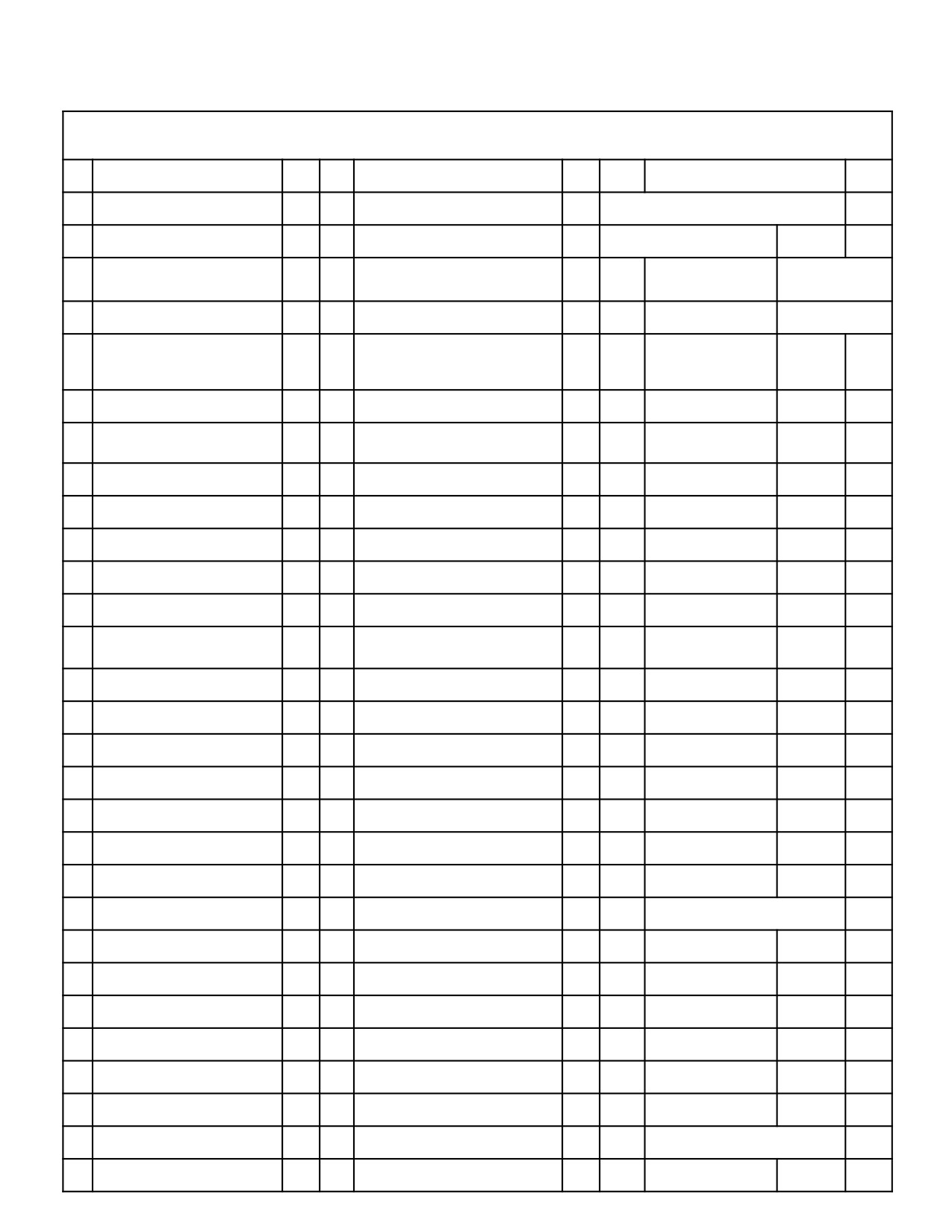
Engine Model _______________________ Engine S/N ___________________________ Bkt. Mfg. _________________________ S/N __________________________
Attachment Type _________________________ Make ______________________ S/N ____________________ Arm Length ___________ Boom Length ___________ Arm
Cyl. S/N ____________________ Bkt. Cyl. S/N ___________________ Boom Cyl. (L.H.) S/N____________________ Boom Cyl. (R.H.) S/N____________________
Place a "C" in the column if the item is CORRECT. Place a "I" in the column if the item is INCORRECT , and explain by item number under the
comments section. Fill in the blanks provided beside each item.
Visual Checks
C/I
Miscellaneous
C/I
Service Diagnostic Check
C/I
1
Appearance (Overall)
11
Basic Machine Operation Proper
40Condition M/H- Mode
Good
12
Support Packages
* Display Number
2
Glass
Manual Missing
* No.
Main Cont. P/No.
1
Dirty
Parts Missing
Program Version
Broken
Fluid Levels / Lubrication
C/I
Eng.Speed Rpm
No.
2
3
Paint Defects
13
Engine Oil Level
Low Idle (Set Val.)
rpm
Cab
14
Low Idle (Meas. Val)
rpm
Engine CoolantoF
Upper Frame
15
Engine Coolant level
High Idle (Set Val.)
rpm
Lower Frame
16
Hydraulic Oil Level
High Idle (Meas. Val)
rpm
Attachments
17
Swing Gear Bath
Auto Accel
rpm
Counterweight
18
Swing Reduction Unit
A/S-Mode High Idle
rpm
4
Cab
19
Travel Reduction Unit - L.H
B/FC-Mode High Idle
rpm
Appearance (Good)
20
Travel Reduction Unit - R.H
* No.
C-1 Pump P-1 w/H.L.
V
14
Cab Mounting
21
Lubricate Attachments
C-1 Pump P-1 w/H.L.
K
Instrument panels
22
Check Fuel Water Sep.
C-1 Pump P-1
V
Seat assembly
23
Check Pilot Filter
C-1 Pump P-1
K
Cab operation levers
Engine Checks
C/I
C-2 Pump P-2 w/H.L.
V
Switches / Controls
24
Air Intake/Exhaust Connections
C-2 Pump P-2 w/H.L.
K
Radio/Speakers
Loose/Misassemble - Connectors
C-2 Pump P-2.
V
Air Cond. / Heating Unit
Leaking - Hoses/Tubes/Fittings
C-2 Pump P-2
K
Gauge / Warning Lamps
25
Exhaust Connections
Cylinder Cycle Times, M/H-Mode
C/I
5
Decals
Loose/Misassemble - Connectors
41
Boom Cyl - Out
Sec
Misapplied / Damaged
Leaking - Hoses/Tubes/Fittings
42
Boom Cyl. - In
Sec
Wrong/Missing Decal
26
Fuel System Connections
43
Arm Cyl. - Out
Sec
6
Hoses,Tubes, Fittings
Loose/Misassemble Connectors
44
Arm Cyl. - In
Sec
Powertrain components
Hoses/Tube/Fitting Leaking
45
Bucket Cyl. - Out
Sec
Upper - Loose/Routing
27
Oil & Fuel Filters
46
Bucket Cyl. - In
Sec
Lower - Loose/Routing
Loose / Leaking
Swing System Performance
C/I
Attach.- Loose/ Routing
28
Fan Belt Adjustment
47
Swing Speed - LH
Sec
7
All Bolts & Fasteners
29
Air Cleaner Elements
48
Swing Speed - RH
Sec
Powertrain components
Missing
Electrical System
C/I
Upper
Damaged
49
Work & Cab Lights
Lower
Hyd. System.Press. (SK70 ~330)
C/I
Inoperable
Attach.
30
Pilot System Pressure
psi
50
Swing Flashers
8
Wiring Harness
31
Main Relief w/H.L. *
psi
Inoperable
Routing / Misassembly
32
Main Relief
psi
51
Horn
Connections loose
33
Dozer Main Relief *
psi
Inoperable
9
Component Fluid Leakage
34
Swing Port Relief - L
psi
52
Pilot Lever Lock Switch
Engine Assembly
35
Swing Port Relief - R
psi
Inoperable
Hyd. Control Valve
( * ) Note: If applicable for specific
53
Travel Alarm
machine
Hyd. Main Pump
Hyd. System Press. (Compact Exc.)
C/I
Inoperable
Hyd. Travel Motor/Red.
36
P1 Main
psi
54
Battery
Hyd. Swing Motor/Red.
37
P2 Main
psi
Electrolyte Level
0 Track Adjustment
38
P3 Main
psi
Charge (Low)
Proper Tension
39
P4 Main
psi
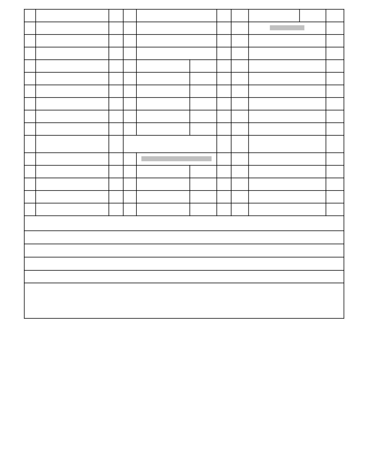
Comments: (Please enter line item # and Description)
Note: Please promptly submit this form to the Kobelco
Service Department via mail or the Kobelco Internet
System. For assistance please contact the Kobelco
Completed By:_____________________________________ Completed Date:________________
Service Dept. at (281) 240-4876
Rev. # 2.0 Form# 00020MIVALL
Page 3-3Dynamic Acera 06/02
NOTES
Dynamic Acera 06/02
Page 3-4
MACHINE FAMILIARIZATION
Cold 0.4 mm (0.0157") Electrical System D.C. 24 V
SK160LC-VI - PERFORMANCE SPECIFICATIONS
Starting Motor 24 V-5.0 kW
The following performance specifications are based on the
stan dard machine with standard attachment.
Alternator 24 V-35 A
Batteries 2- 12 V- (136 Ah) Engine Dry Weight*
1. Travel Speed, Swing Speed & Gradeability
403 kg (888 lbs)
DESCRIPTION SPECIFICATION
Thermostat Begin to open at 76.4°C (169°F). Full open at 90°C
(194°F).
TRAVEL SPEED 6.0 km per hr (3.7 mph) in mode. 4.0 km
Cooling Fan Drive Method Ø545mm (Ø21.5") Suction Type Belt Drive
per hr (2.5 mph) in mode.
Pulley Ratio : 0.85
Air Cleaner Dry Type with Safety Elements *Less flywheel and
SWING SPEED 11 RPM IN M-Mode / “HI” Idle.
electrics.
GRADEABILITY 70% (35°) {Limited by engine lubrication}
3. Hydraulic Components
COMPONENT TYPE
DRAWBAR FORCE 156 KN (35,100 lbs)
2. Engine
HYDRAULIC PUMPS Tandem, Variable Displacement,
MACHINE & COMPONENT WEIGHTS
Engine Maker Mitsubishi
The following weight specifications are based on
Model 4D34-TEG
the standard machine with standard attachment.
Type 4-Cycle, Water Cooled, Direct Injection with Turbocharger,
Diesel
Unit: Kg (lb)
Number of Cylinders- Bore X Stroke 4-104 mm X 115 mm
COMPONENT SK160LC-VI COMPLETE MACHINE
(4.09" X 4.53")
(STANDARD) 16,700 (36,800) UPPER FRAME ASSEMBLY 6,852
Displacement 3.91 liter (238 cu in.) Compression
(15,106) UPPER FRAME + COV & GUARDS 1,831 (4,037)
Ratio 16.5 : 1
COUNTERWEIGH 3,007 (6,629) CAB + ELECT + PANEL +
Output Rating 82 kW (111 HP) / 2,200 rpm Maximum Torque 382
SEAT + AC 415 (915) *BOOM CYLINDER + lower pins 165
N•m (283 lb-ft)/ 1,800 rpm Ignition Order 1-3-4-2 CCW Viewed from
(322) X 2 *ENGINE + MUFFLER + ACCESS 431 (950)
Flywheel Injection Timing 16° Before Top Dead Point Intake Valve
RADIATOR & OIL COOLER 75 (165) PUMP ASSEMBLY +
Clearance Cold 0.4 mm (0.0157") Exhaust Valve Clearance
COUPLER 108 (198) CONTROL VAVE 250 (551) *FUEL TANK
99 (218) *HYDRAULIC TANK 102 (225) SWING MOTOR &
W/ 600mm (23.6") SHOES 1,321 (2,912) X2 ATTACHMENT
REDUCTION UNIT 204 (450) HYDRAULIC PIPES & HOSES 316
(STANDARD) 2,638 (5,816) BUCKET ASSEMBLY [0.52m3 (0.68 yd3)]
(697) LOWER FRAME ASSEMBLY 6,608 (14,568) FRAME +
370 (816) ARM ASSEMBLY [3.10 m (10’-2”)] 857 ( 1,889 ) ARM
Guides + Covers + Piping 2,162 (4,766) SLEWING RING ASSY
[3.10 m (10’-2”)] 564 (1,340) *BUCKET CYL + 2 PINS 142 (313)
218 (481) TRAVEL MOTOR & REDUCTION UNIT 217 (478) X2
IDLER LINKS 32 (71) BUCKET LINK 65 (143) PINS(4- for
TRACK TENSION + IDLERS 210 (463) X2 LOWER ROLLER
bucket, & links) 54 (119) BOOM ASSEMBLY 1,411 (3,111)
ASSEMBLY 35 (77) X14 UPPER ROLLER ASSEMBLY 17 (37)
BOOM + Cyl. pin + Foot pin 1,176 (2,593) *ARM CYLINDER + 2
X4 SPROCKET 72 (159) X2 SWIVEL JOINT 30 (66) TRACK LINK
PINS 215 (474) PIN (Mounting the Arm) 20 (44)
2X143 L/min (2x37.9 Gal/min)
Pump.
Axial Piston with Pilot Gear
RETURN FILTER Safety Valve containing Filter Type OIL
SWING MOTOR Axial Piston
COOLER Air Cooled
TRAVEL MOTOR Axial Piston
FLUIDS 311 (686) HYD OIL 139 (306) ENG OIL 14 (31) FUEL 139
CONTROL VALVES 6 Spool Multiple Control
(306) WATER 19 (42) BOLTS & OTHEER 291 (642) * DRY WEIGHT
CYLINDERS (ALL) Double Acting
Kgf/cm2 (psi)
EQUIPMENT WITH RATED
4. Operating Pressures
CAPACITIES SUFFICIENT TO LIFT
PILOT SYSTEM 50 (710) IMPLEMENT 350
WARNING
THE SPECIFIC COMPONENT(S)
(4980) SWING 285 (4050) TRAVEL 350 (4980)
USE ONLY LIFTING DEVICES AND BEING REMOVED OR INSTALLED.
POWER BOOST/HEAVY LIFT 385 (5470)
Page 3-5Dynamic Acera 06/02
MACHINE FAMILIARIZATION
Air Cleaner Dry Type with Safety Elements *Less flywheel and
ED190 - PERFORMANCE SPECIFICATIONS The
electrics.
following performance specifications are based on the
3. Hydraulic Components
standard machine with standard attachment.
1. Travel Speed, Swing Speed & Gradeability
COMPONENT TYPE
HYDRAULIC PUMPS Tandem, Variable Displacement,
DESCRIPTION SPECIFICATION
MACHINE & COMPONENT WEIGHTS
The following weight specifications are based on
TRAVEL SPEED 6.0 km per hr (3.7 mph) in mode. 3.6 km
per hr (2.2 mph) in mode.
the standard machine with standard attachment.
Unit: Kg (lb)
SWING SPEED 11 RPM IN M-Mode / “HI” Idle.
COMPONENT ED190-VI
GRADEABILITY 70% (35°) Limited by engine lubrication
COMPLETE MACHINE (STANDARD) 19,820 (43,704) UPPER
FRAME ASSEMBLY 6,928 (15,242) UPPER FRAME + COV &
DRAWBAR FORCE 189 KN (42,556 lbs)
GUARDS 1,405 (3.091) COUNTERWEIGHT 3,007 (6,615) CAB +
2. Engine
ELECT + PANEL + SEAT + AC 415 (915) *BOOM CYLINDER +
Engine Maker Mitsubishi
lower pins 165 (322) X 2 *ENGINE + MUFFLER + ACCESS. 431
Model 4D34-TEG
(950) RADIATOR & OIL COOLER 75 (165) PUMP ASSEMBLY +
Type 4-Cycle, Water Cooled, DirectInjection with Turbocharger,
Diesel
COUPLER 108 (238) CONTROL VALVE 250 (551) *FUEL TANK
Number of Cylinders : 4 - Bore X Stroke 104mm X 115mm (4.09" X
99 (218) *HYDRAULIC TANK 102 (225) SWING MOTOR &
4.53") Displacement 3.91 liter (238 cu in.) Compression Ratio
REDUCTION UNIT 204 (450) HYDRAULIC PIPES & HOSES 316
16.5 : 1
(697) LOWER FRAME ASSEMBLY 9,728 (21,402) FRAME +
Output Rating 82 kW (111 HP) / 2,200 rpm Maximum Torque
Guides + Covers + Piping 2,162 (4,766) SLEWING RING ASSY
382 N•m (283 lb-ft)/ 1,800 rpm Ignition Order 1-3-4-2 CCW
218 (481) TRAVEL MOTOR & REDUCTION UNIT 217 (478) X2
Viewed from Flywheel Injection Timing 16° Before Top Dead Point
TRACK TENSION + IDLERS 210 (463) X2 LOWER ROLLER
Intake Valve Clearance Cold 0.4 mm (0.0157") Exhaust Valve
ASSEMBLY 35 (77) X14 UPPER ROLLER ASSEMBLY 17 (37)
Clearance Cold 0.4 mm (0.0157") Electrical System D.C. 24 V
X4 SPROCKET 72 (159) X2 SWIVEL JOINT 30 (66) TRACK LINK
Starting Motor 24 V-5.0 kW
W/ 600mm (23.6") SHOES 1,321 (2,912) X2 ATTACHMENT
Alternator 24 V-35 A
(STANDARD) 2,638 (5,816) BUCKET ASSEMBLY [0.52m3 (0.68 yd3)]
Batteries 2- 12 V- (136 Ah) Engine Dry Weight*
370 (816) ARM ASSEMBLY [3.10 m (10’-2”)] 857 ( 1,889 ) ARM
403 kg (888 lbs)
[3.10 m (10’-2”)] 564 (1,340) *BUCKET CYL + 2 PINS 142 (313)
IDLER LINKS 32 (71) BUCKET LINK 65 (143) PINS(4- for
Thermostat Begin to open at 76.4°C (169°F). Full open at 90°C
(194°F).
bucket, & links) 54 (119) BOOM ASSEMBLY 1,411 (3,111)
Cooling Fan Drive Method Ø545mm (Ø21.5") Suction Type Belt
BOOM + Cyl. pin + Foot pin 1,176 (2,593)
Drive Pulley Ratio : 0.85
2X143 L/min (2x37.9 Gal/min)
*ARM CYLINDER + 2 PINS 215 (474)
Axial Piston with Pilot Gear Pump.
MOTOR Axial Piston
DOZER PUMP Gear Pump 61.6 L/Min (16.3/Gal/min SWING
TRAVEL MOTOR Axial Piston
CONTROL VALVES 7 Spool Multiple Control
WARNING
CYLINDERS (ALL) Double Acting
PILOT SYSTEM 50 (710) IMPLEMENT 350 (4980) SWING 285 (4050)
RETURN FILTER Safety Valve containing Filter Type OIL
TRAVEL 350 (4980) POWER BOOST/HEAVY LIFT 385 (5470)
Kgf/cm2 (psi)
COOLER Air Cooled
USE ONLY LIFTING DEVICES AND EQUIPMENT WITH
4. Operating Pressures
PIN (Mounting the Arm) 20 (44) FLUIDS 311 (686) HYD
RATED CAPACITIES SUFFICIENT TO LIFT THE SPE
OIL 139 (306) ENG OIL 14 (31) FUEL 139 (306) WATER
CIFIC COMPONENT(S) BEING REMOVED OR IN
STALLED.
19 (42) BOLTS & OTHERS 291 (642)
* DRY WEIGHT
Dynamic Acera 06/02
Page 3-6
MACHINE FAMILIARIZATION
Cooling Fan Drive Method Ø600 (Ø24") Suction Type Belt Drive
SK210LC-VI - PERFORMANCE SPECIFICATIONS
Pulley Ratio : 1.00
The following performance specifications are based on the
stan dard machine with standard attachment.
Air Cleaner Dry Type with Safety Elements *Less flywheel and
electrics.
1. Travel Speed, Swing Speed & Gradeability
3. Hydraulic Components
DESCRIPTION SPECIFICATION
COMPONENT TYPE
HYDRAULIC PUMPS Tandem, Variable Displacement,
TRAVEL SPEED 6.0 km per hr (3.7 mph) in mode. 4.0 km
1A. MACHINE & COMPONENT WEIGHTS The
per hr (2.5 mph) in mode.
following weight specifications are based on the
SWING SPEED 11 RPM IN M-Mode / “HI” Idle.
standard machine with standard attachment.
Unit: Kg (lb)
GRADEABILITY 70% (35°) {Limited by engine lubrication}
COMPONENT SK210LC-VI COMPLETE MACHINE
DRAWBAR FORCE 20,190 Kgf (44,512 lbs)
(STANDARD) 20,500 (45,200) UPPER FRAME ASSEMBLY 9,400
2. Engine
(20,720) COUNTERWEIGHT 4,500 (9,920) CAB 260 (570)
Engine Maker Mitsubishi
BOOM CYLINDER* 168 (370) X 2 ENGINE* 470 (1,040)
Model 6D34-TEB
RADIATOR & OIL COOLER 97 (210) PUMP ASSEMBLY 142
Type 4-Cycle, Water Cooled, Direct Injection with Turbocharger,
(310) CONTROL VALVE 280 (620) FUEL TANK* 91 (200)
Diesel
HYDRAULIC TANK* 143 (320) SWING MOTOR & REDUCTION
Number of Cylinders- Bore X Stroke 6-104 mm X 115 mm
UNIT 235 (520) LOWER FRAME ASSEMBLY 7,500 (16,530)
(4.09" X 4.53")
SLEWING RING 245 (540)
TRAVEL MOTOR & REDUCTION UNIT
Displacement 5,861 liter (358 cu in.) Compression
250 (550) X2 IDLER ASSEMBLY 106 (230) X2 LOWER ROLLER
Ratio 16.5 : 1
ASSEMBLY 35 (77) X16 UPPER ROLLER ASSEMBLY 22 (48)
Output Rating 107 kW (144 HP) / 2,000 rpm Maximum Torque 519
X4 TRACK TENSION ASSEMBLY 104 (230) X2 SPROCKET 54
N•m (383 lb-ft)/ 1,600 rpm Ignition Order 1-5-3-6-2-4 Clockwise
(120) X2 SWIVEL JOINT 30 (66) TRACK LINK W/ 800mm (31.5")
Rotation Injection Timing 15° Before Top Dead Point Intake Valve
SHOES 1,720 (3,784) X2 TRACK LINK 540 (1,190) X2
Clearance Cold 0.4 mm (0.0157") Exhaust Valve Clearance Cold
ATTACHMENT (STANDARD) 3,600 (7,930) BUCKET ASSEMBLY
0.4 mm (0.0157") Electrical System D.C. 24 V
[0.81m3 (1.06 cu yd)] 650 (1,430) ARM ASSEMBLY [2.94 m (9’-8”)]
Starting Motor 24 V-5.0 kW
980 (2,160) ARM [2.94 m (9’-8”)] 610 (1,340) BUCKET
CYLINDER* 135 (300) IDLER LINK 21 (46) X2 BUCKET LINK 91
Alternator 24 V-35 A
(200) PIN (2 PCS for mtg bucket cyl & bucket) 65 (140) BOOM
Batteries 2- 12 V- (136 Ah) Engine Dry Weight*
ASSEMBLY 1,650 (3,640) BOOM 1,320 (2,910) ARM
470 kg (1,040 lbs)
CYLINDER* 230 (510) PIN (Mounting the Arm) 27 (59) FLUIDS
Thermostat Begin to open at 76.5°C (170°F). Full open at 90°C
540 (1,190)
(194°F).
2X210 L/min (55.5 Gal/min)
Pump.
Axial Piston with Pilot Gear
RETURN FILTER Safety Valve containing Filter Type OIL
SWING MOTOR Axial Piston
COOLER Air Cooled
TRAVEL MOTOR Axial Piston
HYD OIL 215 (470) ENG OIL 20 (44) FUEL 285 (630) WATER 20
CONTROL VALVES 6 Spool Multiple Control
(44) * DRY WEIGHT
CYLINDERS (ALL) Double Acting
POWER BOOST/HEAVY LIFT 385 (5470)
EQUIPMENT WITH RATED
CAPACITIES SUFFICIENT TO LIFT
Kgf/cm2 (psi)
4. Operating Pressures
THE SPE CIFIC COMPONENT(S)
WARNING
PILOT SYSTEM 50 (710) IMPLEMENT 350
BEING REMOVED OR IN STALLED.
(4980) SWING 285 (4050) TRAVEL 350 (4980) USE ONLY LIFTING DEVICES AND
Page 3-7Dynamic Acera 06/02
MACHINE FAMILIARIZATION
Cooling Fan Drive Method Ø600 (Ø24") Suction Type Belt Drive
SK250LC-VI - PERFORMANCE SPECIFICATIONS
Pulley Ratio : 1.00
The following performance specifications are based on the
Air Cleaner Dry Type with Safety Elements *Less flywheel and
stan dard machine with standard attachment.
electrics.
1. Travel Speed, Swing Speed & Gradeability
3. Hydraulic Components
DESCRIPTION SPECIFICATION
COMPONENT TYPE
HYDRAULIC PUMPS Tandem, Variable Displacement,
TRAVEL SPEED 6.0 km per hr (3.7 mph) in mode. 4.0 km
1A. MACHINE & COMPONENT WEIGHTS The
per hr (2.5 mph) in mode.
following weight specifications are based on the
SWING SPEED 11 RPM IN M-Mode / “HI” Idle.
standard machine with standard attachment. Unit: Kg
(lb)
GRADEABILITY 70% (35°) {Limited by engine lubrication}
COMPONENT SK250LC-VI COMPLETE MACHINE (STANDARD)
DRAWBAR FORCE 20,190 Kgf (44,512 lbs)
24,100 (53,130) UPPER FRAME ASSEMBLY 11,400 (25,130)
2. Engine
COUNTERWEIGHT 5,510 (12,150) CAB 260 (570) BOOM
Engine Maker Mitsubishi
CYLINDER* 220 (490) X 2 ENGINE* 480 (1,060) RADIATOR &
Model 6D34-TLEB
OIL COOLER 97 (210) PUMP ASSEMBLY 142 (310) CONTROL
Type 4-Cycle, Water Cooled, Direct Injection with Turbocharger,
VALVE 280 (620) FUEL TANK* 91 (200) HYDRAULIC TANK* 143
Diesel
(320) SWING MOTOR & REDUCTION UNIT 290 (640) LOWER
Number of Cylinders- Bore X Stroke 6-104 mm X 115 mm (4.09" X
FRAME ASSEMBLY 8,800 (19,400) SLEWING RING 364 (800)
4.53") Displacement 5,861 liter (358 cu in.) Compression Ratio
TRAVEL MOTOR & REDUCTION UNIT 300 (660) X2 IDLER
18.2 : 1
ASSEMBLY 106 (230) X2 LOWER ROLLER ASSEMBLY 35 (77)
Output Rating 125 kW (168 HP) / 2,100 rpm Maximum Torque 590
X16 UPPER ROLLER ASSEMBLY 22 (48) X4 TRACK TENSION
N•m (435 lb-ft)/ 1,600 rpm Ignition Order 1-5-3-6-2-4 Clockwise
ASSEMBLY 94 (210) X2 SPROCKET 54 (120) X2 SWIVEL
Rotation Injection Timing 17° Before Top Dead Point Intake Valve
JOINT 30 (66) TRACK LINK W/ 800mm (31.5") SHOES 1,490 (3,280)
Clearance Cold 0.4 mm (0.0157") Exhaust Valve Clearance Cold
X2 TRACK LINK 580 (1,276) X2 ATTACHMENT (STANDARD)
3,900 (8,600) BUCKET ASSEMBLY [0.81m3 (1.06 cu yd)] 780 (1,720)
0.4 mm (0.0157") Electrical System D.C. 24 V
ARM ASSEMBLY [2.94 m (9’-8”)] 1,150 (2,540) ARM [2.94 m
Starting Motor 24 V-5.0 kW
(9’-8”)] 710 (1,570) BUCKET CYLINDER* 177 (390) IDLER LINK
Alternator 24 V-35 A
25 (55) X2 BUCKET LINK 98 (220) PIN (2 PCS for mtg bucket cyl &
Batteries 2- 12 V- (136 Ah) Engine Dry Weight*
bucket) 80 (180) BOOM ASSEMBLY 2.140 (4,720) BOOM 1,670
470 kg (1,040 lbs)
(3,680) ARM CYLINDER* 300 (660) PIN (Mounting the Arm) 28
Thermostat Begin to open at 76.5°C (170°F). Full open at 90°C
(62)
(194°F).
2X240 L/min (63.4 Gal/min)
Axial Piston with Pilot Gear Pump.
FLUIDS 550 (1,210)
RETURN FILTER Safety Valve containing Filter Type OIL
SWING MOTOR Axial Piston
COOLER Air Cooled
TRAVEL MOTOR Axial Piston
HYD OIL 225 (500) ENG OIL 20 (44) FUEL 285 (630) WATER 22
CONTROL VALVES 6 Spool Multiple Control
(48) * DRY WEIGHT
CYLINDERS (ALL) Double Acting
POWER BOOST/HEAVY LIFT 385 (5470)
USE ONLY LIFTING DEVICES AND
Kgf/cm2 (psi)
EQUIPMENT WITH RATED
4. Operating Pressures
CAPACITIES SUFFICIENT TO LIFT
PILOT SYSTEM 50 (710) IMPLEMENT 350
WARNING
THE SPE CIFIC COMPONENT(S)
(4980) SWING 285 (4050) TRAVEL 350 (4980)
BEING REMOVED OR IN STALLED.
Dynamic Acera 06/02
Page 3-8
MACHINE FAMILIARIZATION
per hr (2.2 mph) in mode.
SK290LC-VI - PERFORMANCE SPECIFICATIONS
The following performance specifications are based on the
SWING SPEED 11 RPM IN M-Mode / “HI” Idle.
stan dard machine with standard attachment.
GRADEABILITY 70% (35°) {Limited by engine lubrication}
1. Travel Speed, Swing Speed & Gradeability
DRAWBAR FORCE 26,218 Kgf (57,800 lbs)
DESCRIPTION SPECIFICATION
2. Engine
Engine Maker Mitsubishi
TRAVEL SPEED 5.6 km per hr (3.5 mph) in mode. 3.5 km
Model 6D16-TLEC
(lb)
Type 4-Cycle, Water Cooled, Direct Injection with Turbo & Inner cooler
Number of Cylinders- Bore X Stroke 6-118 mm X 115 mm (4.65" X
COMPONENT SK290LC-VI COMPLETE MACHINE
4.53") Displacement 7,545 liter (460 cu in.) Compression Ratio
(STANDARD) 30,000 (66,100) UPPER FRAME ASSEMBLY
17.5 : 1
12,937 (28,513) COUNTERWEIGHT 6,118 (13,484) CAB +
Output Rating 138 kW (185 HP) / 2,100 rpm Maximum Torque 726
CONTROLS + A/C + SEAT 836 (1,843) BOOM CYLINDER* 270
N•m (534 lb-ft)/ 1,600 rpm Ignition Order 1-5-3-6-2-4 Clockwise
(595) X 2 ENGINE + MUFFLER + MINOR ITEMS 716 (1,578)
Rotation Injection Timing 15° Before Top Dead Point Intake Valve
RADIATOR & OIL COOLER 175 (386) PUMP ASSEMBLY +
Clearance Cold 0.4 mm (0.0157") Exhaust Valve Clearance Cold
COUPLING 148 (326) CONTROL VALVE 441 (972) FUEL
0.4 mm (0.0157") Electrical System D.C. 24 V
TANK* 170 (375) HYDRAULIC TANK* 173 (381) SWING
MOTOR & REDUCTION UNIT 511 (1,126) UPPER FRAME +
Starting Motor 24 V-5.0 kW
GUARDS & COVERS 3,109 (6,852) LOWER FRAME
Alternator 24 V-35 A
ASSEMBLY 11,232 (24,755) CAR BODY 3,618 (7,974)
Batteries 2- 12 V- (136 Ah) Engine Dry Weight*
SLEWING RING 586 (1,292) TRAVEL MOTOR + RED. UNIT 309
580 kg (1,280 lbs)
(697) X2 IDLER ASSEMBLY 170 (370) X2 LOWER ROLLER
Thermostat Begin to open at 76.5°C (170°F). Full open at 90°C
ASSEMBLY 45 (77) X18 UPPER ROLLER ASSEMBLY 26 (57)
(194°F).
X4 TRACK TENSION ASSEMBLY 127 (280) X2 SPROCKET +
Cooling Fan Drive Method Ø620 (Ø24.2") Suction Type Belt Drive
BOLTS 76 (168) X2 SWIVEL JOINT + LOWER LINES 74 (163)
Pulley Ratio : 0.90
TRACK CHAINS W/800mm (31.5”) SHOES 2,338 (5,153) X2
Air Cleaner Dry Type with Safety Elements *Less flywheel and
TRACK GUIDES + GREASE BATH + MOTOR COVERS 90 (198)
electrics.
ATTACHMENT (STANDARD) 5,136 (11,320) BUCKET
3. Hydraulic Components
ASSEMBLY [1.20M3 (1.57 CU YD)] 954 (2,100) ARM
COMPONENT TYPE
ASSEMBLY [3.2 m (10’- 6”) 1,485 (3,273) ARM 952 (2,098)
HYDRAULIC PUMPS Tandem, Variable Displacement,
BUCKET CYLINDER 220 (485) IDLER LINK 27 (60) X2
1A. MACHINE & COMPONENT WEIGHTS The
BUCKET LINK 130 (290) PIN (6 PCS for mtg bucket cyl, links, bckt
following weight specifications are based on the
&arm cyl rod) 139 (306) BOOM ASSEMBLY 2,697 (5,944)
standard machine with standard attachment. Unit: Kg
2X210 L/min (55.5 Gal/min)
BOOM 2,116 (4,664)
Axial Piston with Pilot Gear Pump.
SWING MOTOR Axial Piston
TRAVEL 350 (4980)
TRAVEL MOTOR Axial Piston
POWER BOOST/HEAVY LIFT 385 (5470)
ARM CYLINDER* 370 (816) PINS (4 PCS for mtg arm cyl, boom cyl’s &
CONTROL VALVES 6 Spool Multiple Control
boom) 211 (465) FLUIDS 554 (1,221) HYD OIL 171 (377) FUEL 348
CYLINDERS (ALL) Double Acting
(767) WATER 35 (77) * DRY WEIGHT
RETURN FILTER Safety Valve containing Filter Type OIL
COOLER Air Cooled
WARNING
USE
4. Operating Pressures
Kgf/cm2 (psi)
ONLY LIFTING DEVICES AND EQUIPMENT WITH
PILOT SYSTEM 50 (710)
RATED CAPACITIES SUFFICIENT TO LIFT THE
IMPLEMENT 350 (4980)
SPECIFIC COMPONENT(S) BEING REMOVED OR
INSTALLED.
SWING 280 (3980)
Page 3-9Dynamic Acera 06/02
MACHINE FAMILIARIZATION
Number of Cylinders- Bore X Stroke 6-118 mm X 115 mm (4.65" X
SK330LC-VI - PERFORMANCE SPECIFICATIONS
The following performance specifications are based on the
4.53") Displacement 7,545 liter (460 cu in.) Compression Ratio
stan dard machine with standard attachment.
17.5 : 1
Output Rating 177 kW (238 Hp) / 2,200 rpm Maximum Torque 824
1. Travel Speed, Swing Speed & Gradeability
N•m (608 lb-ft)/ 1,800 rpm Ignition Order 1-5-3-6-2-4 Clockwise
DESCRIPTION SPECIFICATION
Rotation Injection Timing 14° Before Top Dead Point Intake Valve
Clearance Cold 0.4 mm (0.0157") Exhaust Valve Clearance Cold
TRAVEL SPEED 5.8 km per hr (3.6 mph) in mode. 3.4 km
per hr (2.1 mph) in mode.
0.4 mm (0.0157") Electrical System D.C. 24 V
Starting Motor 24 V-5.0 KW
SWING SPEED 11 RPM IN M-Mode / “HI” Idle.
Alternator 24 V-35 A
GRADEABILITY 70% (35°) {Limited by engine lubrication}
Batteries 2- 12 V- (136 Ah) Engine Dry Weight*
580 kg (1,280 lbs)
DRAWBAR FORCE 28,950 Kgf (63,800 lbf)
2. Engine
Thermostat Begin to open at 76.5°C (170°F). Full open at 90°C
(194°F).
Engine Maker Mitsubishi
Cooling Fan Drive Method Ø620 (Ø24.2") Suction Type Belt Drive
Model 6D16-TLEB
Pulley Ratio : 0.90
Type 4-Cycle, Water Cooled, Direct Injection with Turbo & Innercooler
TANK* 204 (450) HYDRAULIC TANK* 173 (381) SWING
Air Cleaner Dry Type with Safety Elements *Less flywheel and
MOTOR & REDUCTION UNIT 511 (1,126) UPPER FRAME +
electrics.
GUARDS & COVERS 3,800 (8,375) LOWER FRAME
3. Hydraulic Components
ASSEMBLY 12,362 (27,167) CARBODY 3,990 (8,794)
COMPONENT TYPE
SLEWING RING 586 (1,292) TRAVEL MOTOR + RED. UNIT 360
HYDRAULIC PUMPS Tandem, Variable Displacement,
(790) X2 IDLER ASSEMBLY 170 (370) X2 LOWER ROLLER
1A. MACHINE & COMPONENT WEIGHTS The
ASSEMBLY 58 (130) X18 UPPER ROLLER ASSEMBLY 30 (66)
following weight specifications are based on the
X4 TRACK TENSION ASSEMBLY 190 (420) X2 SPROCKET +
standard machine with standard attachment. Unit: Kg
BOLTS 88 (190) X2 SWIVEL JOINT + LOWER LINES 85 (187)
(lb)
TRACK CHAINS W/800mm (31.5”) SHOES 2,390 (5,286) X2
COMPONENT SK330LC-VI COMPLETE MACHINE
TRACK GUIDES + GREASE NBATH + MOTOR COVERS 105 (231)
(STANDARD) 35,300 (77,800) UPPER FRAME ASSEMBLY
ATTACHMENT (STANDARD) 6,134 (13,519) BUCKET
15,998 (35,260) COUNTERWEIGHT 8,420 (18,558) CAB +
ASSEMBLY [1.20M3 (1.57 CU YD)] 1,040 (2,290) ARM
CONTROLS + A/C + SEAT 836 (1,843) BOOM CYLINDER* 270
ASSEMBLY [3.2 m (10’- 6”) 1,785 (3,875) ARM 1,160 (2,560)
(595) X 2 ENGINE + MUFFLER + MINOR ITEMS 716 (1,578)
BUCKET CYLINDER 260 (570) IDLER LINK 27 (60) X2
RADIATOR & OIL COOLER 175 (386) PUMP ASSEMBLY +
BUCKET LINK 130 (290) PIN (6 PCS for mtg bucket cyl, links, bckt
COUPLING 148 (326) CONTROL VALVE 475 (1,047) FUEL
&arm cyl rod) 139 (306) BOOM ASSEMBLY 3,336 (7,353)
2X242 L/min (63.4 Gal/min)
BOOM 2,580 (5,690)
Axial Piston with Pilot Gear Pump.
SWING MOTOR Axial Piston
POWER BOOST/HEAVY LIFT 385 (5470)
ARM CYLINDER* 500 (1,100) PINS (4 PCS for mtg arm cyl, boom cyl’s
TRAVEL MOTOR Axial Piston
& boom) 256 (485) FLUIDS 805 (1,774) HYD OIL 304 (670) FUEL 466
CONTROL VALVES 6 Spool Multiple Control
(1,030) WATER 35 (77) * DRY WEIGHT
CYLINDERS (ALL) Double Acting
RETURN FILTER Safety Valve containing Filter Type OIL
COOLER Air Cooled
WARNING
USE
4. Operating Pressures
ONLY LIFTING DEVICES AND EQUIPMENT WITH
Kgf/cm2 (psi)
RATED CAPACITIES SUFFICIENT TO LIFT THE
PILOT SYSTEM 50 (710)
SPECIFIC COMPONENT(S) BEING REMOVED OR
IMPLEMENT 350 (4980)
INSTALLED.
SWING 280 (3980)
TRAVEL 350 (4980)
Dynamic Acera 06/02
Page 3-10