Hyundai Excavator R450LC-7. Service and repair manual - page 37
 

  Index      Manuals     Hyundai Excavator R450LC-7. Service and repair manual


Search            copyright infringement  


Content      ..     35      36      37      38     ..


Hyundai Excavator R450LC-7. Service and repair manual - page 37


8-159

Disassembly

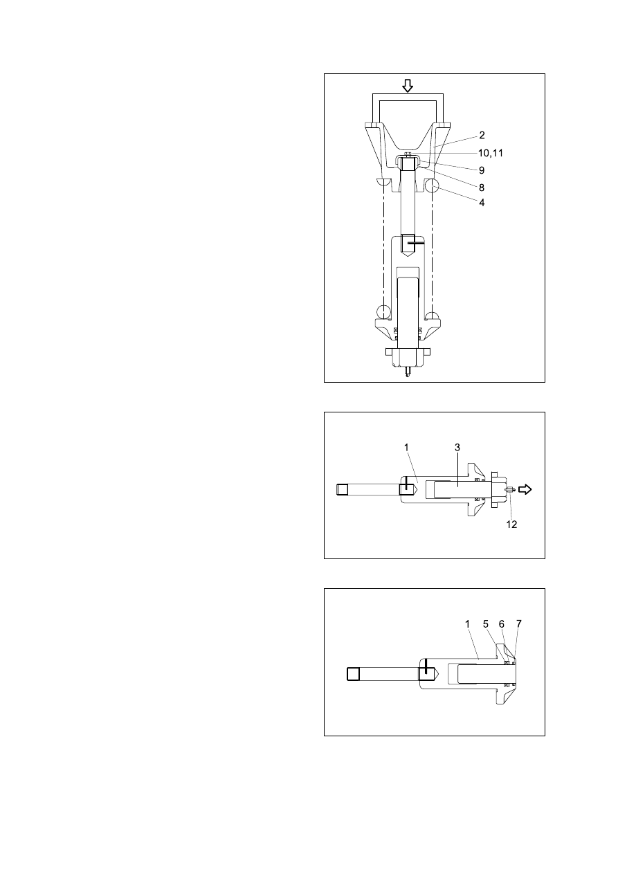
Apply pressure on spring(4) with a press.
The spring is under a large installed load.
This is dangerous, so be sure to set
properly.

·

Spring set load : 24375kg(53737lb)

Remove bolt(10), spring washer(11) and
lock plate(9).
Remove lock nut(8).
Take enough notice so that the press
which pushes down the spring, should
not be slipped out in its operation.
Lighten the press load slowly and
remove bracket(2) and spring(4).

(2)

Remove rod seal(5), back up ring(6) and
dust seal(11).

Remove rod(3) from body(1).
Remove grease valve(12) from rod(3).


45078UC03

45078UC04

45078UC05

8-160

Assembly

Install dust seal(7), back up ring(6) and
rod seal(5) to body(1).
When installing dust seal(7) and rod
seal(5), take full care so as not to
damage the lip.

(3)

Install spring(4) and bracket(2) to body
(1).
Apply pressure to spring(4) with a press
and tighten lock nut(8).
Apply sealant before assembling.
During the operation, pay attention
specially to prevent the press from
slipping out.


Pour grease into body(1), then push in
rod(3) by hand.
After take grease out of grease valve
mounting hole, let air out.
If air letting is not sufficient, it may be
difficult to adjust the tension of crawler.
Fit grease valve(12) to rod(3).

·

Tightening torque : 13.0

±

1.0kgf

·

m

(94

±

7.2lbf

·

ft)

45078UC05

45078UC04

45078UC06

8-161

Lighten the press load and confirm the
set length of spring(4).
After the setting of spring(4), install lock
plate(9), spring washer(11) and bolt(10).

45078UC07

1. STRUCTURE

GROUP  11  WORK EQUIPMENT

B

C

C

A

B

A

8-163

2.  REMOVAL AND INSTALL

BUCKET ASSEMBLY

Removal

Lower the work equipment completely to
ground with back of bucket facing down.

(1)

1)

B

A

Install

Carry out installation in the reverse order
to removal.
When aligning the mounting position of
the pin, do not insert your fingers in the
pin hole.
Adjust the bucket clearance.
For detail, see operation manual.

(2)

Remove nut(3), bolt(4) and draw out the
pin(B).

Remove nut(1), bolt(2) and draw out the
pin(A).

8-174(1) 210-7

8-174(2) 210-7

8-174(3) 210-7

8-174(4) 210-7

8-164

ARM ASSEMBLY 

Removal

Loosen the breather slowly to release the
pressure inside the hydraulic tank.
Escaping  fluid  under  pressure  can
penetrated the skin causing serious
injury.
Remove bucket assembly.
For details, see removal  of  bucket
assembly.
Disconnect bucket cylinder hose(1).
Fit blind  plugs in  the piping at  the
chassis end securely to prevent oil from
spurting out when the engine is started.
Sling arm  cylinder assembly,  remove
spring, pin stopper and pull out pin.
Tie the rod with wire to prevent it from
coming out.
For details, see removal of arm cylinder
assembly.
Place a wooden block under the cylinder
and bring the cylinder down to it.
Remove bolt(2), plate(3) and pull out the
pin(4) then remove the arm assembly.

·

Weight : 1450kg(3200lb)

When lifting the arm assembly, always lift
the center of gravity.

(1)

2

2

)

2, 3, 4

Crane

Install

Carry out  installation in the reverse order
to removal.
When lifting the arm assembly, always lift
the center of gravity.
Bleed the air from the cylinder.

(2)

5

1

1

8-175(1) 210-7

8-175(2) 210-7

8-175(3) 210-7

8-165

BOOM ASSEMBLY

Removal

Remove arm and bucket assembly. 
For details, see removal  of  arm  and
bucket  assembly.
Remove boom cylinder assembly from
boom.
For details, see removal  of  boom
cylinder assembly.

1

2

1

(1)

3

3

)

4, 5, 6

3

Crane

Install

Carry out installation in the reverse order
to removal.
When lifting the boom assembly, always
lift the center of gravity.
Bleed the air from the cylinder.

(2)

Remove bolt(4), plate(5) and pull out the
pin(6) then remove boom assembly.

·

Weight : 3300kg(7360lb)

When lifting the boom assembly always
lift the center of gravity.

Disconnect head lamp wiring.
Disconnect  bucket cylinder  hose(2) and
arm cylinder hose(1).
When the hose are disconnected, oil
may spurt out.
Sling boom assembly(3).


8-176(1) 210-7

8-176(2) 210-7

8-176(3) 210-7

21078DA46

SECTION   9  COMPONENT MOUNTING TORQUE

Group   1  Introduction Guide

9-1

Group   2  Engine System

9-2

Group   3  Electric System

9-4

Group   4  Hydraulic System

9-6

Group   5  Undercarriage

9-9

Group   6  Structure

9-10

Group   7  Work Equipment

9-14

9-1

This section shows bolt specifications and
standard torque values needed when
mounting components to the machine.

Use genuine Hyundai spare parts.
We expressly point out that Hyundai will not
accept any responsibility for defects resulted
from non-genuine parts.
In such cases Hyundai cannot assume
liability for any damage.

Only  metric  fasteners  can  be  used  and
incorrect  fasteners  may  result  in  machine
damage or malfunction.
Before  installation,  clean  all  the  compone-
nts with a non-corrosive cleaner.  Bolts and
threads must not be worn or damaged.

SECTION   9  COMPONENT MOUNTING TORQUE

GROUP  1  INTRODUCTION GUIDE

1.

2.

29079CM00

GROUP  2  ENGINE SYSTEM

E

E

NGINE  AND ACCESSORIES MOUNTING

COOLING SYSTEM AND FUEL TANK MOUNTING

GROUP  3  ELECTRIC SYSTEM

E

E

LECTRIC COMPONENTS MOUNTING 1

45079CM03


Content      ..     35      36      37      38     ..