Hyundai Excavator R450LC-7. Service and repair manual - page 34
 

  Index      Manuals     Hyundai Excavator R450LC-7. Service and repair manual


Search            copyright infringement  


Content      ..     32      33      34      35     ..


Hyundai Excavator R450LC-7. Service and repair manual - page 34


8-121

Remove lock nut(20) and then boot(25).

(15)

RE18 (210-7)

RE19 (210-7)

RE20 (210-7)

8-122

Cleaning of parts

Put all parts  in rough cleaning  vessel
filled with kerosene and clean them
(Rough cleaning).
If dirty part is cleaned with kerosene just
after putting it in vessel, it may be
damaged.  Leave it in kerosene for a
while to loosen dust and dirty oil.
If this kerosene is polluted, parts will be
damaged and functions of reassembled
valve will be degraded.
Therefore,  control  cleanliness  of
kerosene fully.
Put parts in final cleaning vessel filled
with kerosene, turning it slowly to clean
them even to their insides (Finish
cleaning).
Do not dry parts with compressed air,
since they will be damaged and/or rusted
by dust and moisture in air.

Rust prevention of parts.
Apply rust-preventives to all parts.
If left as they after being cleaned, they will
be rusted and will not display their
functions fully after being reassembled.

(16)

(17)

8-123

Assemble spring(10) into casing.
Assemble reducing valve subassembly
into casing.
Assemble them to their original positions.

(4)

Stand spool vertically with its bottom
placed on flat workbench, and with spring
seat pushed down, put two pieces of
semicircular stopper(9) on spring seat
without piling them on.
Assemble stopper(9) so that its sharp
edge side will be caught by head of spool.
Do not push down spring seat more than
6mm.

(3)

Put shim(6), springs(7, 29) and spring
seat(8, 30) onto spool(5) in this order.

(2)

A

A

SSEMBLY

Tighten hexagon socket head plug(2) to
the specified torque.
Tighten two bolts alternately and slowly.

(1)

4)

RE29 (210-7)

RE30 (210-7)

RE31 (210-7)

RE32 (210-7)

8-124

Assemble plug subassembly to casing.
When return spring is weak in force,
subassembly stops due to resistance of
O-ring.

(8)

Assemble push rod(14) to plug(11).
Apply working oil on push-rod surface.

(7)

Assemble seal(12) to plug(11).
Assemble seal in such lip direction as
shown below.

(6)

Assemble O-ring(13) onto plug(11).

(5)

RE33 (210-7)

RE34 (210-7)

RE35 (210-7)

RE36 (210-7)

8-125

Assemble plate(18) to joint(17).
Screw it to position that it contacts with 4
push rods evenly.
Do not screw it over.

(12)

Tighten joint(17) with the specified torque
to casing, utilizing jig.

(11)

Fit plate(15).

(10)

When  return spring  is strong in  force,
assemble 4 sets at the same time, utilizing
plate(15), and tighten joint(17) temporarily.

(9)

Assemble adjusting nut(19), apply
spanner to width across flat of plate(18) to
fix it, and tighten adjusting nut to the
specified torque.
During tightening, do not change position
of disk.

(13)

RE37 (210-7)

RE38 (210-7)

RE39 (210-7)

RE40 (210-7)

8-126

Assemble bushing(16) to plate and pass
cord and tube through it.
Provide margin necessary to operation.

(16)

Pull out cord and tube through adjusting
nut hole provided in direction 60

to 120

from casing hole.

(15)

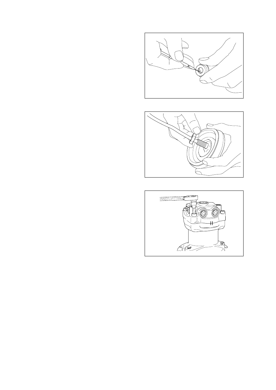
Fit boot(25) and lock nut(20), and handle
subassembly is assembled completely.

(14)

25038RL02(4)

RE48 (210-7)

25038RL03(1)

25038RL03(2)

8-127

Inject volatile rust-preventives through all
ports and then put blind plugs in ports.

(20)

Assemble lower end of bellows to casing.

(19)

Apply grease to rotating section of joint
and contacting faces of disk and push rod.

(18)

Determine handle direction, tighten lock
nut(20) to specified torque to fix handle.

(17)

25038RL03(3)

25038RL03(4)

25038RL04

1.  REMOVAL AND INSTALL

REMOVAL 

Lower the work equipment to the ground
and stop the engine.

Operate the control levers and pedals
several times to release the remaining
pressure in the hydraulic piping.

Loosen the breather slowly to release the
pressure inside the hydraulic tank.
Escaping fluid under pressure can
penetrate the skin causing serious injury.
When pipes and hoses are disconnected,
the oil inside the piping will flow out, so
catch it in oil pan.

Disconnect all hoses .

Sling the turning joint assembly (1) and
remove the mounting bolt(2).

·

Weight : 50kg(110lb)

·

Tightening torque : 29.7

±

45kgf

·

m

(215

±

32.5lbf

·

ft)

Remove the turning joint assembly.
When removing the turning joint, check
that all the hoses have been disconnected.

8-128

G

GROUP  8  TURNING JOINT

1

2

1

1)

(1)

(2)

(3)

(4)

(5)

(6)

INSTALL

Carry out installation in the reverse order
to removal.
Take care of turning joint direction.
Assemble hoses to their original positions.
Confirm the hydraulic oil level and check
the hydraulic oil leak or not.

2)

(1)


45078TJ01

45078TJ02

13031GE18

8-129

2.  DISASSEMBLY AND ASSEMBLY

STRUCTURE

1)

1

Hub

2

Shaft assembly

3

Cover

4

Spacer

5

Shim

6

Shim

7

Slipper seal

8

O-ring

9

O-ring

10

O-ring

11

Plug

12

Plug

13

Retaining ring

14

Hexagon bolt

15

Spring washer

4

5

7

1

9

8

12

14

15

2

11

10

13

6

3

R210TJT2

8-130

14

15

3

Remove six slipper seals(7) and O-
ring(9), from body(1).

(5)

Place body(1) on a V-block and by using a
wood buffer at the shaft end, hit out
shaft(2) to about 1/2 from the body with a
hammer.
Take care not to damage the shaft(2)
when remove body(1) or rest it sideway.
Put a fitting mark on body(1) and shaft(2).

(4)

Remove shim(6) and O-ring(10).

Remove retainer ring(13), spacer(4) and
shim(5).

(2)

(3)

D

DISASSEMBLY

Before the disassembly, clean the turning
joint.
Remove bolts(14), washer(15) and
cover(3).

2) 

(1)

21078DA10

45078DA11

45078DA12

8-131

Fit shim(5), spacer(4) and retainer ring
(13) to shaft(2).

Fit O-ring(10) to body(1).

Fit shim(6) to shaft(2).

(4)

(5)

(6)

Set shaft(2) on block, tap body(1) with a
plastic hammer to install.

(3)

Fix seven slipper seal(7) and O-ring(9), to
body(1).

Fit O-ring(8) to shaft(2).

(1)

(2)

ASSEMBLY

Clean all parts.
As a general rule, replace oil seals and O-
ring.
Coat the sliding surfaces of all parts with
engine oil or grease before installing.

3) 


45078DA12

45078DA13

45078DA11

8-132

14

15

3

Install cover(3) to body(1) and tighten
bolts(14).

·

Torque : 10~12.5kgf

·

m(72.3~90.4lbf

·

ft)

(7)

21078DA10

1.  REMOVAL AND INSTALL

BUCKET CYLINDER

Removal
Expand the arm and bucket fully, lower the
work equipment to the ground and stop
the engine.
Operate the control levers and pedals
several times to release the remaining
pressure in the hydraulic piping.
Loosen the breather slowly to release the
pressure inside the hydraulic tank.
Escaping fluid under pressure can
penetrate the skin causing serious injury.
Fit blind plugs in the hoses after
disconnecting them, to prevent dirt or dust
from entering.

Set block between bucket cylinder and
arm.

8-133

GROUP  9  BOOM, ARM AND BUCKET CYLINDER

1)

(1)

Disconnect bucket cylinder hoses(4) and
put plugs(5) on cylinder pipe.

Remove bolt(2), nut(3) and pull out pin
(1).
Tie the rod with wire to prevent it from
coming out.

Wooden block

Arm

Bucket Cylinder

1

2

3

5

4

4

13031GE18

29078CY001

29078CY002

29078CY003

8-134

Install

Carry out installation in the reverse order
to removal.
When aligning the mounting position of
the pin, do not insert your fingers in the
pin hole.
Bleed the air from the bucket cylinder.
Confirm the hydraulic oil level and check
the hydraulic oil leak or not.

5

6

8


(

(

2)

Sling bucket cylinder assembly(8) and
remove bolt(6) then pull out pin (5).
Remove bucket cylinder assembly(8).

·

Weight : 300kg(660lb)

29078CY004

8-135

ARM CYLINDER 

Removal
Expand the arm and bucket fully, lower the
work equipment  to the ground  and stop
the engine.
Operate the control levers and pedals
several times to release the remaining
pressure in the hydraulic piping.
Loosen the breather slowly to release the
pressure inside the hydraulic tank.
Escaping fluid under pressure can
penetrate the skin causing serious injury.
Fit  blind  plugs  in  the  hoses  after
disconnecting them,  to prevent  dirt  or
dust from entering.

Set block between arm cylinder and
boom.

Block

Arm cylinder

1

2

5

4

2)

(1)

Disconnect arm cylinder hoses(4) and
put plugs on cylinder pipe.
Disconnect greasing pipings(5).

Remove bolt(2) and pull out pin(1).
Tie the rod with wire to prevent it from
coming out.


13031GE18

29078CY01

29078CY02

29078CY03

8-136

Install

Carry out installation in the reverse order
to removal.
When aligning the mounting position of
the pin, do not insert your fingers in the
pin hole.
Bleed the air from the arm cylinder.
Confirm the hydraulic oil level and check
the hydraulic oil leak or not.


(

(

2)

Sling arm assembly(8) and remove bolt
(7) then pull out pin(6).
Remove arm cylinder assembly(8).

·

Weight : 540kg(1190lb)

8

6

7

29078CY04


Content      ..     32      33      34      35     ..