Hyundai Excavator R450LC-7. Service and repair manual - page 4
 

  Index      Manuals     Hyundai Excavator R450LC-7. Service and repair manual


Search            copyright infringement  


Content      ..     2      3      4      5     ..


Hyundai Excavator R450LC-7. Service and repair manual - page 4


2-10

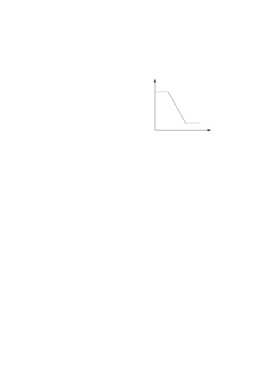
Negative flow control
By changing the pilot pressure Pi, the
pump tilting angle(delivery flow) is
regulated arbitrarily, as shown in the
figure.
This regulator is of the negative flow
control in which the delivery flow Q
decreases as the pilot pressure Pi rises.
With this mechanism, when the pilot
pressure corresponding to the flow
required for the work is commanded, the
pump discharges the required flow only,
and so it does not consume the power
uselessly.

REGULATOR
Regulator consists of the negative flow control, total horse power control and power shift control
function.

2)

(1) 

Pilot pressure, P

i

Deliv

er

y flo

w

, Q

2-11

Flow reducing function

As the pilot pressure Pi rises, the pilot piston(643) moves to the right to a position where the force of the
pilot spring(646) balances with the hydraulic force.
The groove(A) in the pilot piston is fitted with the pin(875) that is fixed to lever 2(613).  Therefore, when
the pilot piston moves, lever 2 rotates around the fulcrum of point B [Fixed by the fulcrum plug(614) and
pin(875)].  Since the large hole section(C) of lever 2 contains a protruding pin(897) fixed to the feedback
lever(611), the pin(897) moves to the right as lever 2 rotates.  Since the opposing-flat section(D) of the
feedback lever is fitted with the pin(548) fixed by the tilting pin(531) that swings the swash plate, the
feedback lever rotates around the fulcrum of point D, as the pin(897) moves.
Since the feedback lever is connected with the spool(652) via the pin(874), the spool moves to the right.
The movement of the spool causes the delivery pressure P1 to connect to port CL through the spool
and to be admitted to the large diameter section of the servo piston.  The delivery pressure P1 that is
constantly admitted to the small diameter section of the servo piston moves the servo piston to the right
due to the area difference, resulting in decrease of the tilting angle.
When the servo piston moves to the right, point D also moves to the right.  The spool is fitted with the
return spring(654) and is tensioned to the left at all times, and so the pin(897) is pressed against the
large hole section(C) of lever 2.
Therefore, as point D moves, the feedback lever rotates around the fulcrum of point C, and the spool is
shifted to the left.  This causes the opening between the sleeve(651) and spool(652) to close slowly,
and the servo piston comes to a complete stop when it closes completely.

45070RG07

2-12

Flow increasing function

As the pilot pressure Pi decreases, the pilot piston(643) moves to the left by the action of the pilot
spring(646) and causes lever 2(613) to rotate around the fulcrum of point B.   Since the pin(897) is
pressed against the large hole section(C) of lever 2 by the action of the return spring(654) via the
spool(652), pin(874), and feedback lever(611), the feedback lever rotates around the fulcrum of
point D as lever 2 rotates, and shifts the spool to the left.  Port CL opens a way to the tank port as
the spool moves.  This deprives the large diameter section of the servo piston of pressure, and
shifts the servo piston to the left by the discharge pressure P1 in the small diameter section,
resulting in an increase in the flow rate.
As the servo piston moves, point D also moves to the left, the feedback lever rotates around the
fulcrum of point C, and the spool moves to the right till the opening between the spool and sleeve is
closed.

45070RG08

2-13

The flow control characteristic can be
adjusted with the adjusting screw.
Adjust it by loosening the hexagon nut
(801) and by tightening(or loosening) the
hexagonal socket head screw(924).
Tightening the screw shifts the control
chart to the right as shown in the figure.

Adjusting values are shown in table.

Pilot pressure, P

i

Delivery flow, Q

Tightening

amount of

adjusting

screw(924)

(Turn)

+1/4

Flow control 

starting

pressure

change
amount

(kgf/cm

2

)

+1.7

Flow

change 
amount 

(

/min)

+22.7

Adjustment of flow control

characteristic

Speed

(min 

-1

)

1900

801
924

Adjustment of flow control characteristic

2-12 (210-7)

2-14

Total horsepower control

The regulator decreases the pump tilting
angle(delivery flow) automatically to limit
the input torque within a certain value with
a rise in the delivery pressure P1 of the
self pump and the delivery pressure P2 of
the companion pump.
(The input horsepower is constant when
the speed is constant.)
Since the regulator is of the simultaneous
total horsepower type that operates by the
sum of load pressures of the two pumps
in the tandem double-pump system, the
prime mover is automatically prevented
from being overloaded, irrespective of the
load condition of the two pumps, when
horsepower control is under way.
Since this regulator is of the simultaneous
total horsepower type, it controls the tilting
angles(displacement volumes) of the two
pumps to the same value as represented
by the following equation :
Tin = P1

×

q/2

Л

+ P2

×

q/2

Л

= (P1+P2)

×

q/2

Л

The horsepower control function is the
same as the flow control function and is
summarized in the following.(For detailed
behaviors of respective parts, refer to the
section of flow control).

(

(

2)

Delivery pressure, (P

1

+P

2

)

Deliv

er

y flo

w

, Q

2-15

Overload preventive function

When the self pump delivery pressure P1 or the companion pump delivery pressure P2 rises, it
acts on the stepped part of the compensating piston(621).  It presses the compensating rod(623)
to the right till the force of the outer spring(625) and inner spring(626) balances with the hydraulic
force.  The movement of the compensating rod is transmitted to lever 1(612) via pin(875).
Lever 1 rotates around the pin(875) (E) fixed to the casing(601).
Since the large hole section(F) of lever 1 contains a protruding pin(897) fixed to the feedback
lever(611), the feedback lever rotates around the fulcrum of point D as lever 1 rotates, and then
the spool(652) is shifted to the right.  As the spool moves, the delivery pressure P1 is admitted to
the large diameter section of the servo piston via port CL, causes the servo piston move to the
right, reduces the pump delivery, flow rate, and prevents the prime mover from being overloaded.
The movement of the servo piston is transmitted to the feedback lever via point D.  Then the
feedback lever rotates around the fulcrum of point F and  the spool is shifted to the left.  The
spool moves till the opening between the spool(652) and sleeve(651) is closed.

45070RG09

2-16

Flow reset function

As the self pump delivery pressure P1 or the companion pump delivery pressure P2 decreases,
the compensating rod(623) is pushed back by the action of the springs(625 & 626) to rotate lever
1(612) around point E.  Rotating of lever 1 causes the feedback lever(611) to rotate around the
fulcrum of point D and then the spool(652) to move to the left.   As a result, port CL opens a way
to the tank port.
This causes the servo piston to move to the left and the pump's delivery rate to increase.
The movement of the servo piston is transmitted to the spool by the action of the feedback
mechanism to move it till the opening between the spool and sleeve is closed.

45070RG10

2-17

Adjustment of outer spring
Adjust it by loosening the hexagon
nut(630) and by tightening(or loosening)
the adjusting screw C(628).   Tightening
the screw shifts the control chart to the
right and increases the input
horsepower as shown in the figure.
Since turning the adjusting screw C by
N turns changes the setting of the inner
spring(626), return the adjusting screw
CI(925) by N

×

A turns at first.(A=1.9)

A

A

djusting values are shown in table.

Low tilting angle(low flow) command preferential function
As mentioned above, flow control and horsepower control tilting angle commands are
transmitted to the feedback lever and spool via the large-hole sections(C & F) of levers 1 and 2.
However, since sections C and F have the pins(

Ø

4) protruding from the large hole(

Ø

8), only the

lever lessening the tilting angle contacts the pin(897) ; the hole(

Ø

8) in the lever of a larger tilting

angle command is freed without contacting the pin(897).  Such a mechanical selection method
permits preference of the lower tilting angle command of the flow control and horsepower
control.

A

A

djustment of input horsepower

Since the regulator is of total cumulative horsepower type, adjust the adjusting screws of both
the front and rear pumps, when changing the horsepower set values.  The pressure change
values by adjustment are based on two pumps pressurized at the same time, and the values will
be doubled when only one pump is loaded.

a.

Delivery pressure, (P

1

+P

2

)

Deliv

er

y flo

w

, Q

Adjustment of outer spring

Speed

Tightening 

Compens- Input 

torque

amount of 

ating control 

change 

adjusting starting  amount
screw(C)

pressure 

(628)

change 
amount

(min 

-1

)

(Turn)

(kgf/cm

2

)

(kgf

·

m)

1900

+1/4

+19.2

+4.9

625 

626   

630       628

801

925

2-16 (210-7)

2-18

Adjustment of inner spring
Adjust it by loosening the hexagon nut
(801) and by tightening(or loosening)
the adjusting screw QI(925).    
Tightening the screw increases the flow
and then the input horsepower as
shown in the figure.

Adjusting valves are shown in table.

b.

Adjustment of inner spring

Speed

Tightening 

Compens- Input 

torque

amount of 

ating control 

change 

adjusting starting  amount

screw(QI)

pressure 

(925)

change 
amount

(min 

-1

)

(Turn)

(kgf/cm

2

)

(kgf

·

m)

1900

+1/4

+16.3

+4.2

Delivery pressure, (P

1

+P

2

)

Deliv

er

y flo

w

, Q

626

801

925

2-17 (210-7)

2-19

Power shift control

The set horsepower valve is shifted by varying
the command current level of the proportional
pressure reducing valve attached to the pump.
Only one proportional pressure reducing valve is
provided.  However, the secondary pressure Pf
(power shift pressure) is admitted to the
horsepower control section of each pump
regulator through the pump's internal path to
shift it to the same set horsepower level.
This function permits arbitrary setting of the
pump output power, thereby providing the optimum power level according to the operating
condition.
The power shift pressure Pf controls the set horsepower of the pump to a desired level, as shown
in the figure.
As the power shift pressure Pf rises, the compensating rod(623) moves to the right via the
pin(898) and compensating piston(621).
This decreases the pump tilting angle and then the set horsepower in the same way as explained
in the overload preventive function of the horsepower control.  On the contrary, the set horsepower
rises as the power shift pressure Pf falls.

(3)

Delivery pressure, (P

1

+P

2

)

Deliv

er

y flo

w

, Q

P

f

=MAX.

P

f

=MIN.

45070RG11

2-20

Adjustment of maximum flow
Adjust it by loosening the hexagon
nut(806) and by tightening(or loosening)
the set screw(953).
The maximum flow only is adjusted without
changing other control characteristics.

Adjustment of minimum flow
Adjust it by loosening the hexagon
nut(807) and by tightening(or loosening)
the hexagonal socket head set screw
(954).  Similarly to the adjustment of the
maximum flow, other characteristics are
not changed. 
However, remember that, if tightened too
much, the required horsepower during
the maximum delivery pressure(or during
relieving) may increase.

Adjustment of max flow

Flow  change

amount

(

/min)

Tightening

amount of

adjusting screw

(953)

(Turn)

Speed

(min 

-1

)

1900

+1/4

-7.6

Adjustment of min flow

Flow  change

amount

(

/min)

Tightening

amount of

adjusting screw

(954)

(Turn)

Speed

(min 

-1

)

1900

+1/4

+7.6

Pilot pressure, P

i

Deliv

er

y flo

w

, Q

Pilot pressure, P

i

Deliv

er

y flo

w

, Q

Adjustment of maximum and minimum flows

(4)

45070RG12

45070RG13


Content      ..     2      3      4      5     ..