EMCO WinNC GE Series Fanuc 21 MB. Software description/ Software version from 13.76 - page 2
 

  Index      Manuals     EMCO WinNC GE Series Fanuc 21 MB. Software description/ Software version from 13.76


Search            copyright infringement  


Content      ..      1      2      3      ..


EMCO WinNC GE Series Fanuc 21 MB. Software description/ Software version from 13.76 - page 2


EMCO W

IN

NC GE S

ERIES

 F

ANUC

 21

MB

O

PERATING

 S

EQUENCES

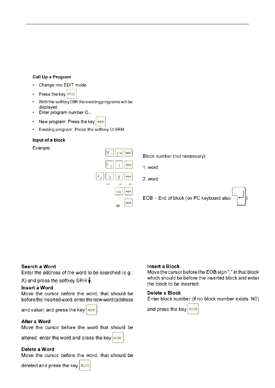
Program Input

Part programs and subprograms can be entered in

the EDIT mode.

Note:

With the parameter SEQUENCE NO (PARAMETER

MANUELL)  you  can  determine  whether  block

numbering should occur automatically (1 = yes, 0 =

no).
EMCO W

IN

NC GE S

ERIES

 F

ANUC

 21

MB

O

PERATING

 S

EQUENCES

NOTE
When you use an interface expansion card (e.g. for

COM 3 and COM 4), take care that for every interface

a  separate  interrupt  is  used  (e.g.:  COM1  -  IRQ4,

COM2 - IRQ3, COM3 - IRQ11, COM4 - IRQ10).

Delete a Program

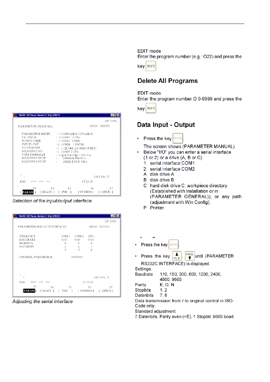
Adjusting the Serial Interface

Control parameter:

Bit 0: 1...Transmission will be cancelled with ETX

(End of Text) code

0...Transmission will be cancelled with RESET

Bit 7: 1...Overwrite part program without message

0...Message, if a program already exists

ETX code: % (25H)

EMCO W

IN

NC GE S

ERIES

 F

ANUC

 21

MB

C 6

O

PERATING

 S

EQUENCES

Program Output

• EDIT mode

• Enter the receiver in (PARAMETER MANUAL)

below "I/O".

• Press the softkey OPRT.

• Press the key F11.

• Press the soktkey PUNCH

• Enter the program number to be send (e.g. O22).

• When you enter e.g. O5-15, all programs with the

numbers 5 to inclusive 15 will be printed.

When you enter the program numbers 0-9999 all

programs will be put out.

• Press softkey EXEC

Program Input

• EDIT mode

• Enter the receiver in (PARAMETER MANUAL)

below "I/O".

•


Prss th k

e

 prog

• Press the softkey OPRT

• Press key F11.

• Press softkey READ

• With input from disk or hard disk you have to enter

a program number.

Enter the program number when you want to read

in one program (e.g.: O22).

When you enter e.g. O5-15, all programs with the

numbers 5 to inclusive 15 will be transmitted.

When you enter O-9999 as program number, all

programs will be transmitted.

• Press the softkey EXEC.

Tool Offset Output

• EDIT mode

• Enter the receiver in (PARAMETER MANUAL)

below "I/O".

Tool Offset Input

• EDIT mode

• Enter the receiver in (PARAMETER MANUAL)

below "I/O".

Print Programs

• The printer (standard printer in Windows) must be

connected and must be in ON LINE status.

• EDIT mode

• Enter  P  (Printer)  as  receiver  in  (PARAMETER

MANUAL) below "I/O".

•


Prss th

e

 k

e

 prog

• Press the softkey OPRT.

• Press the key F11.

• Press the softkey PUNCH.

• Enter the program to be printed (e.g. O22) when

you want to print one program.

When you enter e.g. O5-15, all programs with the

numbers 5 to inclusive 15 will be printed.

When you enter the program number O-9999 all

programs will be printed.

• Press the softkey EXEC.

EMCO W

IN

NC GE S

ERIES

 F

ANUC

 21

MB

O

PERATING

 S

EQUENCES

Program Run

Start of a Part Program

Before starting a program the control and the machine

must be ready for running the program.

• Select the EDIT mode.

Displays while Program Run

While program run different values can be shown.
• Press the softkey PRGRM (basic status). While

program  run  the  actual  program  block  will  be

displayed.

• Press the softkey CHECK . While program run the

actual program block, the actual positions, active

G and M commands and speed, feed and tool will

be displayed.

• Press the softkey CURRNT. While the program

run the aktiv G commands will be displayed.

Block Search

With this function you can start a program at any

block.

While  block  search  the  same  calculations  will  be

proceeded as with normal program run but the slides

do not move.

Program Influence

DRY RUN

DRY RUN is used for testing programs. The main

spindle will not be switched on and all movements

occur in rapid feed.

If DRY RUN is active, DRY will be displayed in the first

line on the screen.

SKIP

With SKIP all program blocks which are marked with

a "/"  (e.g.: /N0120 G00 X... ) will not be proceeded

and the program will be continued with the next block

without a "/" sign.

If SKIP is active, SKP will be displayed in the first line

on the screen.

Program interruption

EMCO W

IN

NC GE S

ERIES

 F

ANUC

 21

MB

C 8

O

PERATING

 S

EQUENCES

Part Counter and Piece Time

Below the position display the part counter and the

piece time are displayed.

The part counter shows the number of program runs.

Each M30 (or M02) increases the part counter for 1.

RUN TIME shows the complete running time of all

program runs.

CYCLE TIME shows the running time of the actual

program and will be reset to 0 with every program

start.

Part Counter Reset

• Press softkey POS.

• Press softkey OPRT

• Select between PTSPRE (reset part counter to 0)

or RUNPRE (reset run time to 0).

Preset of the Part Counter

The  part  counter  can  be  preset  in  (PARAMETER

TIMER).

Therefore move the curor on the desired value and

enter the new value.

PARTS TOTAL:

Each M30 increases this number by 1. Every pro-

gram run of every program will be counted (= number

of all program runs).

PARTS REQUIRED:

Preset part number. When this number is reached

the  program  will  be  stopped  and  message  7043

PIECE COUNT REACHED will be displayed.

After  that  the  program  can  be  started  only  after

resetting the part counter or increasing the preset

part number.

EMCO W

IN

NC GE S

ERIES

 F

ANUC

 21

MB

O

PERATING

 S

EQUENCES

Graphic Simulation

NC-programs can be simulated graphically.

EMCO W

IN

NC GE S

ERIES

 F

ANUC

 21

MB

P

ROGRAMMING

D 1

D: Programming

Program Structure

CNC programming for machine tools according to

DIN 66025 is used.

The CNC program is a sequence of program blocks

which are stored in the control.

With machining of workpieces these blocks will be

read and checked by the computer in the programmed

order.

The corresponding control signals will be sent to the

machine.

The CNC program consists of:

• Program number

• CNC blocks

• Words

• Addresses

• number combinations (for axis addresses partly

with sign)

Used Addresses

C........... chamfer

F ........... feed rate, thread pitch

G .......... path function

H........... number of the correction value address in

the offset register (OFFSET)

I, J, K .... circle parameter, scale factor, K also

number of repetitions of a cycle,

mirror axes

M .......... miscellaneous function

N........... block number 1 to 9999

O .......... Program number 1 to 9499

P ........... dwell, subprogram call

Q .......... cutting depth or shift value in cycle

R........... radius, retraction height with cycle

S ........... spindle speed

T ........... tool call

X, Y, Z .. position data (X also dwell)

; ............ block end

EMCO W

IN

NC GE S

ERIES

 F

ANUC

 21

MB

P

ROGRAMMING

D 2

Survey of  G Commands

G00

1 .......................

Positioning (Rapid Traverse)

G01 .............. Linear Interpolation

G02 .............. Circular Interpolation Clockwise

G03.............. Circular Interpolation  Counterclockwise

G04² ............. Dwell

G09² ............. Exact Stop

G10 .............. Data Setting

G11 .............. Data Setting Off

G15

1 .......................

End Polar Coordinate Interpolation

G16 .............. Begin Polar Coordinate Interpolation

G17

1 .......................

Plane Selection XY

G18 .............. Plane Selection ZX

G19 .............. Plane Selection YZ

G20 .............. Measuring in Inches

G21 .............. Measuring in Millimeter

G28² ............. Approach Reference Point

G40

1 .......................

Cancel Cutter Radius Compensation

G41 .............. Cutter Radius Compensation left

G42 .............. Cutter Radius Compensation right

G43.............. Tool Length Compensation positive

G44 .............. Tool Length Compensation negative

G49

1 .......................

Cancel Tool Length Compensation

G50

1 .......................

Cancel Scale Factor

G51 .............. Scale Factor

G52² ............. Local Coordinate System

G53² ............. Machine Coordinate System

G54

1 .......................

Zero Offset 1

G55 .............. Zero Offset 2

G56 .............. Zero Offset 3

G57 .............. Zero Offset 4

G58 .............. Zero Offset 5

G59 .............. Zero Offset 6

G61 .............. Exact Stop Mode

G62 .............. Automatic Corner Override

G63.............. Thread Cuting Mode On

G64

1 .......................

Cutting mode

G68 .............. Coordinate System Rotation ON

G69 .............. Coordinate System Rotation OFF

G73.............. Chip Break Drilling Cycle

G74 .............. Left Tapping Cycle

G76 .............. Fine Drilling Cycle

G80

1 .......................

Cancel Drilling Cycles (G83 bis G85)

G81 .............. Drilling Cycle

G82 .............. Drilling Cycle with Dwell

G83.............. Withdrawal Drilling Cycle

G84 .............. Tapping Cycle

G85 .............. Reaming Cycle

G86 .............. Drilling Cycle with Spindle Stop

G87 .............. Back Pocket Drilling Cycle

G88 .............. Drilling Cycle with Program Stop

G89 .............. Reaming Cycle with Dwell

G90

1 .......................

Absolute Programming

G91 .............. Incremental Programming

G92² ............. Coordinate System Setting

G94

1 .......................

Feed per Minute

G95 .............. Feed per Revolution

G97

1 .......................

Revolutions per Minute

G98

1 .......................

Retraction to Starting Plane (Drilling Cycles)

G99 .............. Retraction to Withdrawal Plane

1 ...............................

Einschaltzustand

² ................. Nur satzweise wirksam

*URXS &RPPDQG

)XQFWLRQ

*

'ZHOO

*

([DFWVWRS

*

'DWD6HWWLQJ

*

'DWD6HWWLQJ2II

*

$SSURDFK5HIHUHQFH3RLQW

*

/RFDO&RRUGLQDWH6\VWHP

*

0DFKLQH&RRUGLQDW6\VWHP

*

&RRUGLQDWH6\WHP6HWWLQJ

*

3RVLWLRQLQJ5DSLG7UDYHUVH

*

/LQHDU,QWHUSRODWLRQ

*

&LUFXODU,QWHUSRODWLRQ&ORFNZLVH

*

&LUFXODU,QWHUSRODWLRQ&RXQWHUFORFNZLVH

*

3ODQH6HOHFWLRQ;<

*

3ODQH6HOHFWLRQ=;

*

3ODQH6HOHFWLRQ<=

*

$SVROXWH3URJUDPPLQJ

*

,QFUHPHQWDO3URJUDPPLQJ

*

)HHGSHU0LQXWH

*

)HHGSHU5HYROXWLRQ

*

0HDVXULQJLQ,QFKHV

*

0HDVXULQJLQ0LOOLPHWHU

*

&DQFHO&XWWHU5DGLXV&RPSHQVDWLRQ

*

&XWWHU5DGLXV&RPSHQVDWLRQOHIW

*

&XWWHU5DGLXV&RPSHQVDWLRQ5LJKW

*

7RRO/HQJKW&RPSHQVDWLRQSRVLWLYH

*

7RROOHQJKW&RPSHQVDWLRQQHJDWLYH

*

&DQFHO7RRO/HQJKW&RPSHQVDWLRQ

*

&KLS%UHDN'ULOOLQJ&\FOH

*

/HIW7DSSLQJ&\FOH

*

)LQH'ULOOLQJ&\FOH

*

&DQFHO'ULOOLQJ&\FOHV

*

'ULOOLQJ&\FOH

*

'ULOOLQJ&\FOHZLWK'ZHOO

*

:LWKGUDZLQJ'ULOOLQJ&\FOH

*

7DSSLQJ&\FOH

*

5HDPLQJ&\FOH

*

'ULOOLQJ&\FOHZLWK6SLQGOH6WRS

*

%DFN3RFNHW'ULOOLQJ&\FOH

*

'ULOOLQJ&\FOHZLWK3URJUDP6WRS

*

5HDPLQJ&\FOHZLWK'ZHOO

*

5HWUDFWLRQWR6WDUWLQJ3ODQH

*

5HWUDFLRQWR:LWKGUDZDO3ODQH

*

&DQFHO6FDOH)DFWRU

*

6FDOH)DFWRU

*

5HYROXWLRQVSHU0LQXWH

*

=HUR2IIVHW

*

=HUR2IIVHW

*

=HUR2IIVHW

*

=HUR2IIVHW

*

=HUR2IIVHW

*

=HUR2IIVHW

*

([DFW6WRS0RGH

*

7KUHDG&XWWLQJ0RGH21

*

&XWWLQJ0RGH

*

&RRUGLQDWH6\VWHP5RWDWLRQ21

*

&RRUGLQDWH6\VWHP5RWDWLRQ2))

*

(QG3RODU&RRUGLQDWH,QWHUSRODWLRQ

*

%HJLQ3RODU&RRUGLQDWH,QWHUSRODWLRQ

EMCO W

IN

NC GE S

ERIES

 F

ANUC

 21

MB

P

ROGRAMMING

D 3

Survey of M Commands

M00 ...... Programmed Stop

M01 ...... Programmed Stop, Conditional

M02 ...... Program End

M03 ...... Main Spindle ON Clockwise

M04 ...... Main Spindle ON Counterclockwise

M05

1 ..........

Main Spindle OFF

M06 ...... Tool Change

M08 ...... Coolant ON

M09

1 ..........

Coolant OFF

M10 ...... Lock dividing head

M11 ...... Unlock dividing head

M19 ...... Oriented Spindle Stop

M25 ...... Release Clamping Device

M26 ...... Close Clamping Device

M30 ...... Program End

M71 ...... Puff blowing ON

M72

1 ..........

Puff blowing OFF

M98 ...... Subprogram Call

M99 ...... Subprogram End

1 ...............................

Initial status

EMCO W

IN

NC GE S

ERIES

 F

ANUC

 21

MB

P

ROGRAMMING

D 4

Description of G Commands

G00  Positioning (Rapid Traverse)

Format

N....  G00  X...  Y...  Z...

The slides are traversed at maximum speed to the

programmed target point (tool change position, start

point for a following machining routine)

Notes

• A programmed feed F will be suppressed while

G00

• The maximum speed is defined by the producer of

the machine

• The feed override switch is active

Example
absolute G90

N50  G00  X40  Y56

incremental G91

N50  G00  X-30  Y-30.5

G01  Linear Interpolation

Format

N...  G01  X...  Y...  Z....  F....
Straight movements at the programmed feed rate.

Example
absolute G90

N..  G94

.....

N20  G01  X40  Y20.1  F500

incremental G91

N.. G94  F500

.....

N20  G01  X20  Y-25.9

EMCO W

IN

NC GE S

ERIES

 F

ANUC

 21

MB

P

ROGRAMMING

D 5

Chamfers and Radius

By programming the parameter C or R a chamfer or

a radius can be inserted between two G00 or G01

movements.

Format:

N..  G00/G01   X.. Y..  C/R

N..  G00/G01   X.. Y..

Programming of chamfers and radii is possible for

the active plane only. Following the programming in

the XY plane (G17) is described.

The movement which is programmed has to start at

point b of the drawing.

With  incremental  programming  the  distance  from

point b must be programmed.

With single block mode the tool starts first at point c

and then at point d.

The following situations cause an error message:
• If  the  traverse  path  in  one  of  the  two  G00/G01

blocks is so short, that with inserting a chamfer or

a radius no intersection point would be existing,

error message no. 055 will appear.

• If in the second block no G00/G01 command is

programmed, error message no. 51, 52 will appear.

EMCO W

IN

NC GE S

ERIES

 F

ANUC

 21

MB

P

ROGRAMMING

D 6

Helix curve

G02 Circular Interpolation

Clockwise

G03 Circular Interpolation

Counterclockwise

Format

N...  G02/G03  X...  Y...  Z...  I...  J... K...  F...

or

N...  G02/G03  X...  Y...  Z...  R...  F...

X, Y, Z .. End point of the arc (abs. or incr.)

I, J, K .... Incremental circle parameter

(distance  from  start  point  to  the  centre

point, I is related to X, J to Y, K to Z)

R........... Radius of the arc (arc < semicircle with +R,

> semicircle with -R), can be programmed

instead of the circle parameter I, J, K

The tool will be traversed along the defined arc with

the programmed feed F.

Notes

The circular interpolation can be proceeded in the

active plane only.

Programming the value 0 for I, J or K can be omitted.

The observation of G02, G03 occurs always vertical

to the active plane.

Helix Interpolation

Normally only two axes will be programmed for a

circle. These axes determine also the active plane.

If  a  third  vertical  axis  will  be  programmed,  the

movements of the slides will be coupled in a way that

a screw line results.

The programmed feed rate will not be hold at the real

path, but on the circle path (projected). The third,

linear traversed axis will be controlled in a way, that

it  reaches  the  end  point  at  the  same  time  as  the

circular traversed axes.

Limitations

• A  helix  interpolation  is  possible  with  G17  (XY

plane) only.

• The gradient angle 

φ

 must be less than 45°.

• If the spatial tangents differ more than 2° with

block transititions, an exact stop will be proceeded

in every case before/after the helix.

EMCO W

IN

NC GE S

ERIES

 F

ANUC

 21

MB

P

ROGRAMMING

D 7

G04 Dwell

Format

N...  G04  X...

[sec]

or

N...  G04   P...

[msec]

The tool movement will be stopped for a time defined

by X or P in the last reached position - sharp edges

- transititions, cleaning drilling ground, exact stop

Notes

• With address P no decimal point can be used

• The  dwell  starts  at  the  moment  when  the  tool

movement speed from the last movement becomes

zero.

• t max. = 2000 sec

• Input resolution 100 msec (0.1 sec)

Examples

N75  G04  X2.5

(Dwell = 2.5 sec)

N95  G04  P1000

(Dwell = 1sec = 1000 msec)

EMCO W

IN

NC GE S

ERIES

 F

ANUC

 21

MB

P

ROGRAMMING

D 8

G7.1 Cylindrical Interpolation

Notes:

· The reference point of the cylinder must be entered

incrementally,  since  otherwise  it  would  be

approached by the tool!

· In the offset data cutter position 0 must be allocated

to  the  tool.  However,  the  miller  radius  must  be

entered.

· In mode G7.1 the coordinate system must not be

changed.

· G7.1 Q.. and/or G13.1 Q0 must be programmed in

the mode "cutter radius compensation off" (G40)

and cannot be started or terminated within "cutter

radius compensation on" (G41 or G42).

· G7.1 Q.. and G7.1  Q0 must be programmed in

separate blocks.

This function enables the development of a cylinder

surface in programming.

In  this  way  e.g.  programs  for  cyclindrical  cam

machining on lathes can be created.
The traverse amount of the rotary axis Q programmed

by indication of the angle is converted in the control

into the distance of a fictitious linear axis along the

external surface of the cylinder.

Thus,  it  is  possible  that  linear  and  circular

interpolations on this area can be carried out with

another axis.

With G19 the level is determined in which the rotary

axis Q is preset in parallel to the Y-axis.

· In  a  block  between  G7.1  Q..  and  G7.1  Q0  an

interrupted program cannot be restarted.

· The arc radius with circular interpolation (G2 or G3)

must be programmed via an R-command and must

not be programmed in degree and/or via K and J-

coordinates.

· In the geometry program between G7.1 Q.. and

G7.1 Q0 no rapid motion (G0) and/or positioning

procedures causing rapid motion movements (G28)

or drilling cycles (G83 to G89) must be programmed.

· The feed entered in the mode cylindric interpolation

is  to  be  considered  as  traverse  speed  on  the

unrolled cylinder area.

Format:

N...  G7.1   Q...

N...  G7.1   Q0

The tool tip position 0 must be programmed for all

tools that will be used for the cylindrical interpolation.

G7.1 Q...

Starts the cylinder interpolation.

The Q- value describes the radius of

the the blank part.

G7.1  Q0

End of cylinder interpolation

4

EMCO W

IN

NC GE S

ERIES

 F

ANUC

 21

MB

P

ROGRAMMING

D 9

Example - Cylindrical Interpolation

X axis with diametrical programming and Q axis with

angular programming.

O0002 (Cylindrical Interpol.)

N15 T0505

N25 M13

Sense of rotation for driven tools

             (be equivalent to M3)

N30 G97 S2000

N32 M52

 Positioning of the spindle

N35 G7.1 Q19.1

Start of the interpolation /

blank part radius

N37  G94  F200

N40 G0 X45 Z-5

N45 G1 X35 Q0 Z-5

N50 G1 Z-15 Q22.5

N55 Z-5 Q45

N60 Z-15 Q67.5

N65 Z-5 Q90

N70 Z-15 Q112.5

N75 Z-5 Q135

N80 Z-15 Q157.5

N85 Z-5 Q180

N90 Z-15 Q202.5

N95 Z-5 Q225

N100 Z-15 Q247.5

N105 Z-5 Q270

N110 Z-15 Q292.5

N115 Z-5 Q315

N120 Z-15 Q337.5

N125 Z-5 Q360

N130 X45

N135 G7.1 Q0

End of interpolation

N140 M53

End of roundaxis

operation

N145 G0 X80 Z100 M15

N150 M30

EMCO W

IN

NC GE S

ERIES

 F

ANUC

 21

MB

P

ROGRAMMING

D 10

G10 Data Setting

The command G10 allows to overwrite control data,

programming parameters, writing tool data etc...

G10 is frequently used to program the workpiece

zero point.

Zero point offset

Format

N... G10 L2 Pp IP...;

p=0

External workpiece zero point offset

p=1-6

Normal workpiece zero point offset

corrresponding to the coordinatesystem

1 - 6

IP

Workpiece zero point offset for the

several axis.

At the programming IP become

replaced by the axsletters (X,X,Z).

Tool Compensation

Format

N... G10 L11 P...R...;

P

Number of the toll compensation

R

Tool compensation value in the im absolute

command- Mode (G90).

At  the  inkremental  value  programming  (G91)  the

tool compensation value get add up to the existing

value.

Note: By the reason of compatibility with older  NC-

programms the system allow the input of L1 instead

of L11

G09 Exact Stop

Format

N...  G09
A block will then be proceeded, when the slides are

braked to 0 before. Therefore the edges will not be

rounded and precise transititions will result.

G09 is effective blockwise.


Content      ..      1      2      3      ..