SANY Crawler Hydraulic Excavator (SY195C9, SY205C9, SY215C9, SY225C9). Shop Manual (2013) - page 29
Disassembly and Assembly
9.
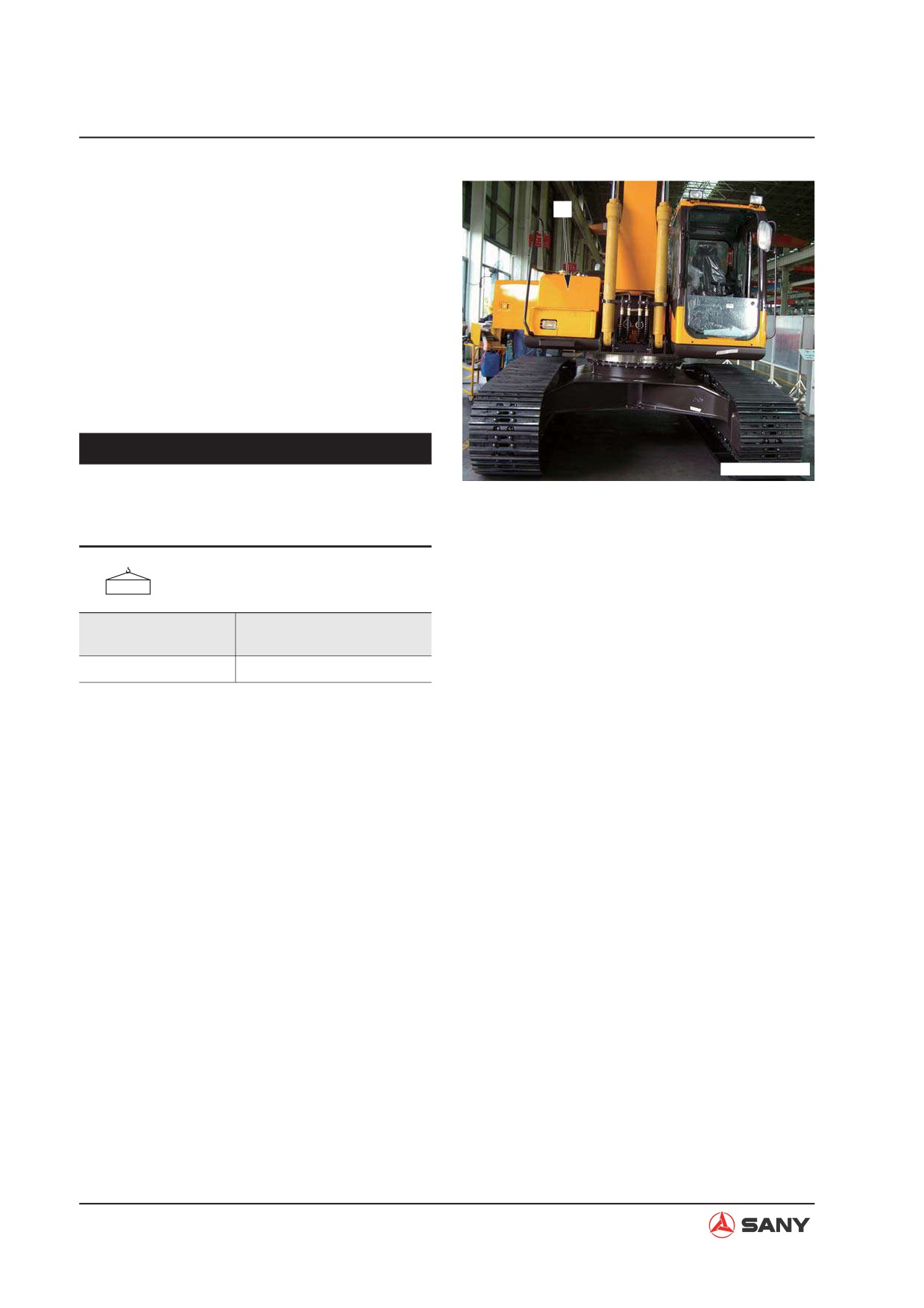
Unscrew the 32 swing platform mounting
bolts in order to remove the swing platform
15
assembly (15). Lift the swing platform as-
sembly off the machine.
NOTE: Remove the front and rear mount-
ing bolts of the platform. Use a lever block
to adjust the swing platform so that the
platform can reach a balance both longi-
tudinally and laterally. Remove the last two
bolts finally.
NOTICE
ZX215T-1006113
Ɣ
Be careful not to impact the central
swivel joint while removing the swing
platform assembly.
Swing platform assembly:
Swing Platform
Assembly
Only (Ref.)
8,427 kg
1,689 kg
8-70
Disassembly and Assembly
8.18.2 Installation
Ɣ Installation is to be performed in the re-
verse order of removal.
Clamping screws (air intake hose):
5.4~6.4 N·m {0.55~0.65 kgf·m}
Mating surface (swing bearing):
Flat surface sealant (Tonsun 1596)
Threads (bolt - swing platform):
Thread adhesive: (Tonsun 1277)
Mounting bolts (swing platform):
Step 1: Tighten the bolts with a pneumatic
spanner.
Step 2: tighten them again.
490~608 N·m {50~62 kgf·m}
Ɣ Hydraulic oil adding
Add through the filler opening the hydraulic
oil to the specified level. Start the engine
to circulate oil in the hydraulic system, and
check the oil level again.
Ɣ Air bleeding
Bleed the air from the travel motor.
For more information, see “Air in Each
Component - Bleed” on page 6-46.
8-71
Disassembly and Assembly
8.19 Swivel Joint AS - Remove and Install
8.19.1 Removal
WARNING
Ɣ Release residual pressure in the hy-
draulic circuit before disconnecting the
hydraulic hoses.
Refer to “Residual Pressure in Hydraulic Cir-
cuit - Release” on page 6-40.
NOTE: Tag each line so as to ensure correc-
tion installation.
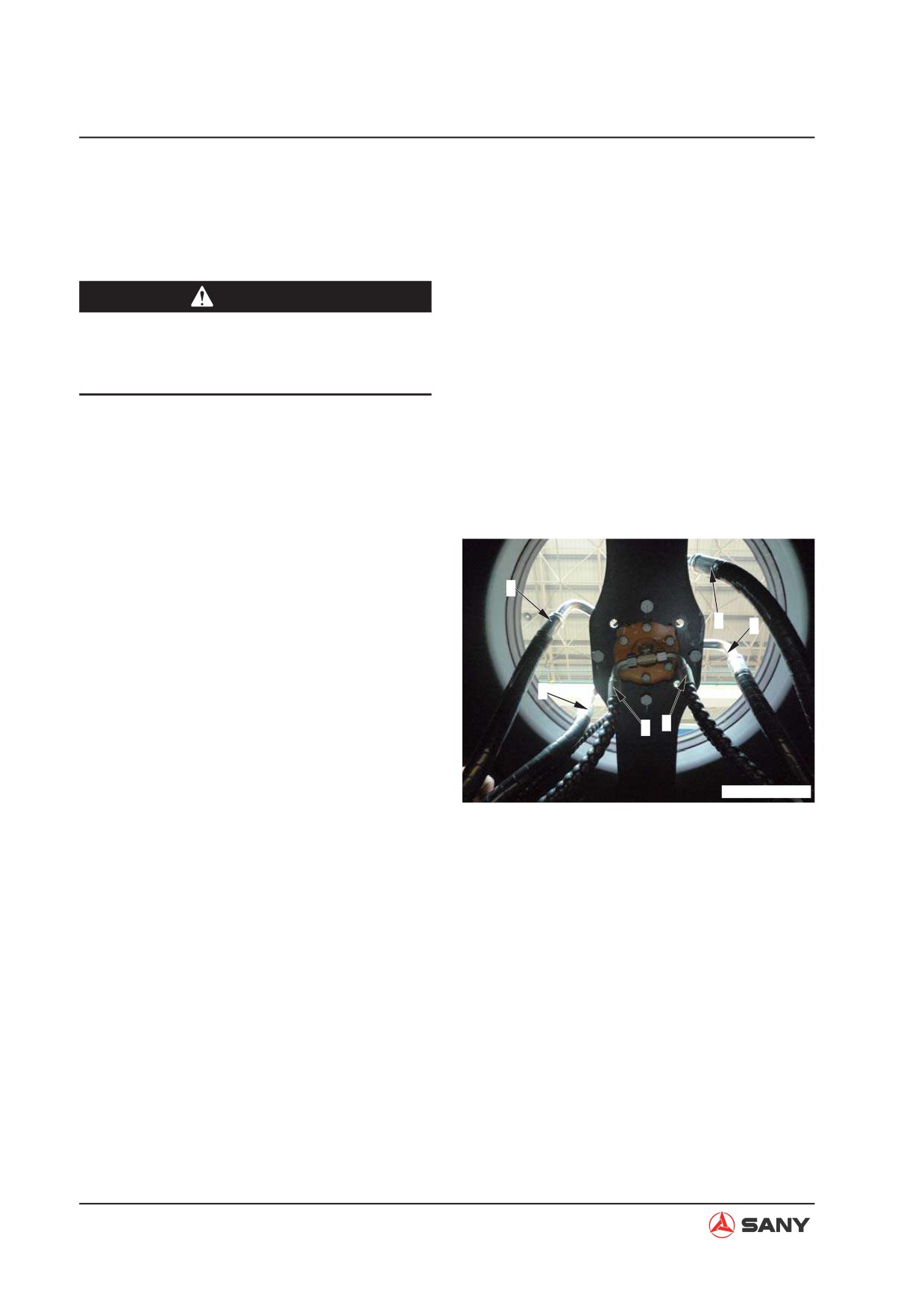
1. Disconnect the six hoses from (1) to (6) on
the central swivel joint of the travel motor.
4
1) Central swivel joint (port T) - Left travel
3
motor (port T)
5
2) Central swivel joint (port T) - Right trav-
el motor (port T)
6
3) Central swivel joint (port B) - Left travel
1
2
motor (port PA)
4) Central swivel joint (port D) - Right trav-
ZX215T-1006114
el motor (port PB)
5) Central swivel joint (port A) - Left travel
motor (port PB)
6) Central swivel joint (port C) - Right trav-
el motor (port PA)
8-72
Disassembly and Assembly
2.
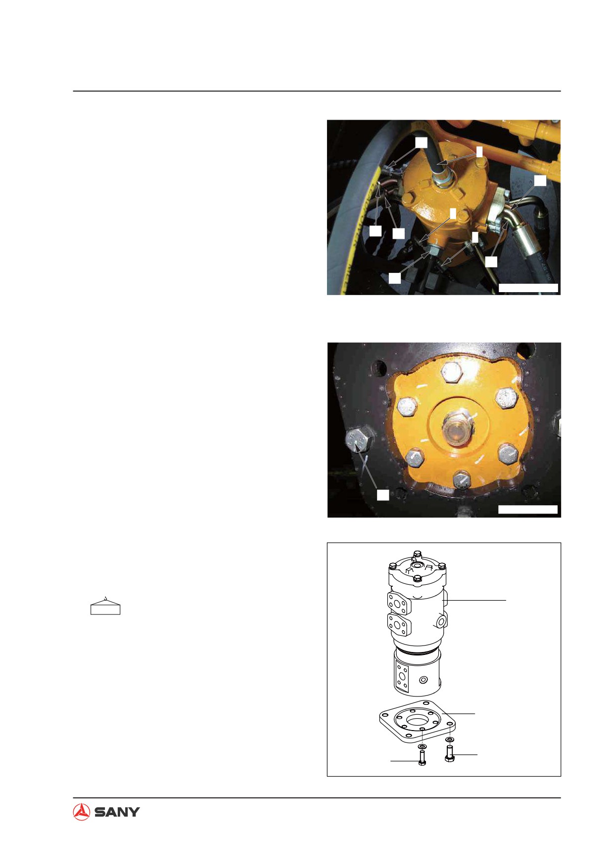
Disconnect the eight hoses from (7) to (14).
10
7) Central swivel joint (port F) - Left travel
9
motor (port P)
13
8) Central swivel joint (port F) - Right trav-
el motor (port P)
7
9) Central swivel joint (port G) - Swing
11
12
motor (port T)
8
10) Central swivel joint (port F) - Solenoid
14
valve
15
ZX215T-1006115
11) Central swivel joint (port C) - Left travel
control valve (port ATL)
12) Central swivel joint (port A) - Left travel
control valve (port BTL)
13) Central swivel joint (port D) - Right trav-
el control valve (port ATR)
14) Central swivel joint (port B) - Right trav-
el control valve (port BTR)
3.
Remove the fixing bolt (15).
4.
Remove the four mounting bolts (16).
16
ZX215T-1006116
5.
Remove the six mounting bolts (17) from
the transition plate. Remove the swivel
joint assembly (18).
18
Central swivel joint: 56 kg
Transition plate
16
17
ZX215-1006117
8-73
Disassembly and Assembly
8.19.2 Installation
Ɣ Installation is to be performed in the re-
verse order of removal.
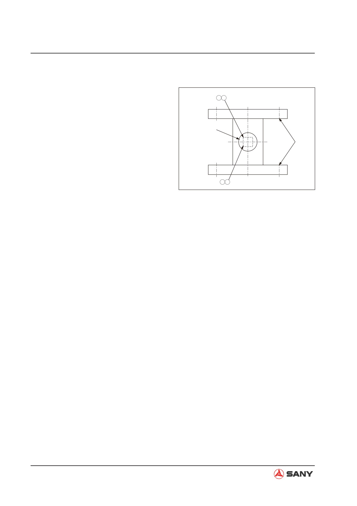
B D
NOTE: Install the central swivel joint facing
the direction indicated in the illustration.
Central swivel joint
Sprocket
Ɣ Oil adding (hydraulic tank)
Add through the filler opening the hydraulic
oil to the specified level. Start the engine
to circulate oil in the hydraulic system, and
AC
ZX215-1006118
check the oil level again.
Ɣ Air bleeding
Bleed the air from the travel motor.
For more information, see “Air in Each
Component - Bleed” on page 6-46.
8-74
Disassembly and Assembly
8.20 Swivel Joint AS - Disassemble and Assemble
8.20.1 Disassembly
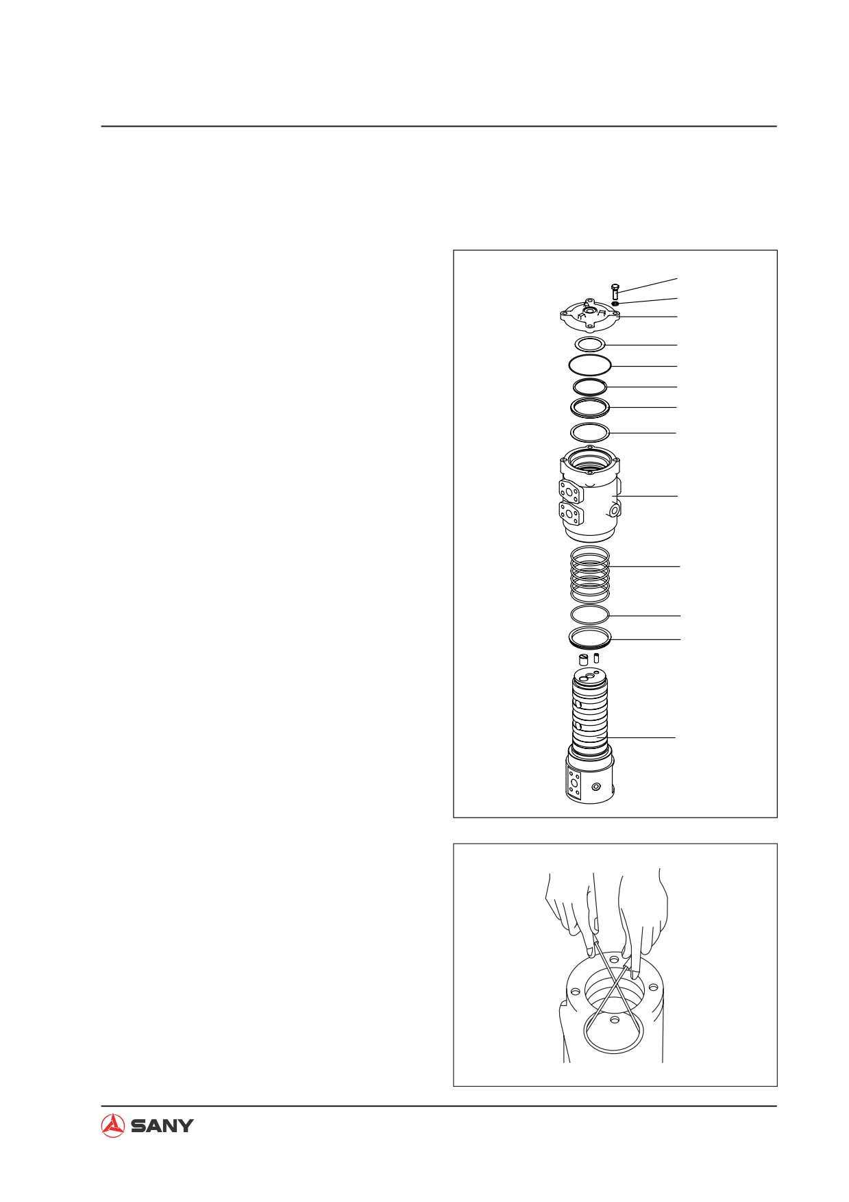
1. Remove the bolt (1) and the spring washer
(2).
1
2
2. Remove the cover (3).
3
3. Remove the gasket (4), O-ring (5) and
4
snap ring (6).
5
6
4. Remove the rotor (13) from the housing (9).
7
NOTE: Be careful not to damage the slid-
8
ing surface of the seal of the rotor (13).
5. Remove the spacer (7) and the gasket (8)
from the housing (9).
9
6. Remove the dust seal (12) from the swing
shaft (13).
10
7. Remove the O-ring seal (11) and the seals
(10) from the housing (9).
11
12
13
ZX215-1006119
ZX215-1006120
8-75
Disassembly and Assembly
8.20.2 Assembly
1.
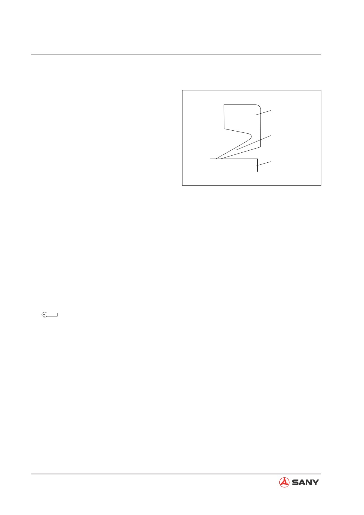
Install the dust seal (12) on the rotor (13).
NOTE: Let the lip face the housing while
Dust seal
installing the dust seal.
2.
Install the six seals (10) in the housing (9).
Lip
3.
Fix the rotor (13) on a work bench. Install
the housing (9) on the rotor (13).
Body
NOTE: Since the clearance between
the housing (9) and the rotor (13) is ap-
ZX215-1006121
proximately 0.1 mm, install the housing (9)
on the rotor (13) slowly and vertically. Be
careful not to damage the seals (10) and
the O-ring seal (11).
4.
Use a rubber hammer to tap the housing (9)
in order to match the rotor (13) properly.
5.
Install the spacer (7) and gasket (8) in the
housing (9).
6.
Install the gasket (4), O-ring seal (5) and
snap ring (6) on the rotor (13).
7.
Install the cover (3). Tighten the bolts (1)
and the spring washer (2).
Fixing bolts: 49 N·m{5 kgf·m}
8-76
Disassembly and Assembly
8.21 Hydraulic Tank AS - Remove and Install
8.21.1 Removal
1. Drain the hydraulic oil into a suitable
container for storage or disposal.
1
Hydraulic oil: approx. 225 L
2
5
4
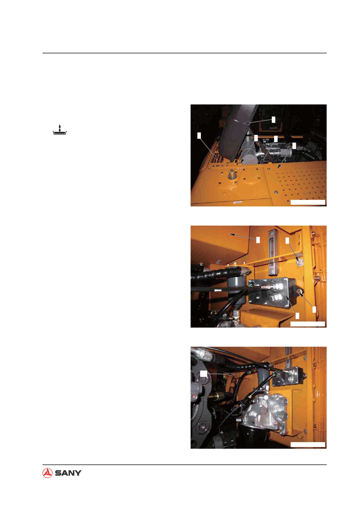
2. Open the engine hood.
3
3. Remove the engine hood (1), cover (2) and
control valve cover (3).
4. Remove the cover mounting frame (4) and
the screen (5).
ZX215T-1006122
5. Remove the screen (6) and the partition
frame mounting bolt (7) on the hydraulic
6
7
tank side.
6. Remove the screw (8) and the fuel control
motor (9).
8
9
ZX215T-1006123
7. Remove the two oil return hoses (10) from
the hydraulic tank.
10
ZX215T-1006124
8-77
Disassembly and Assembly
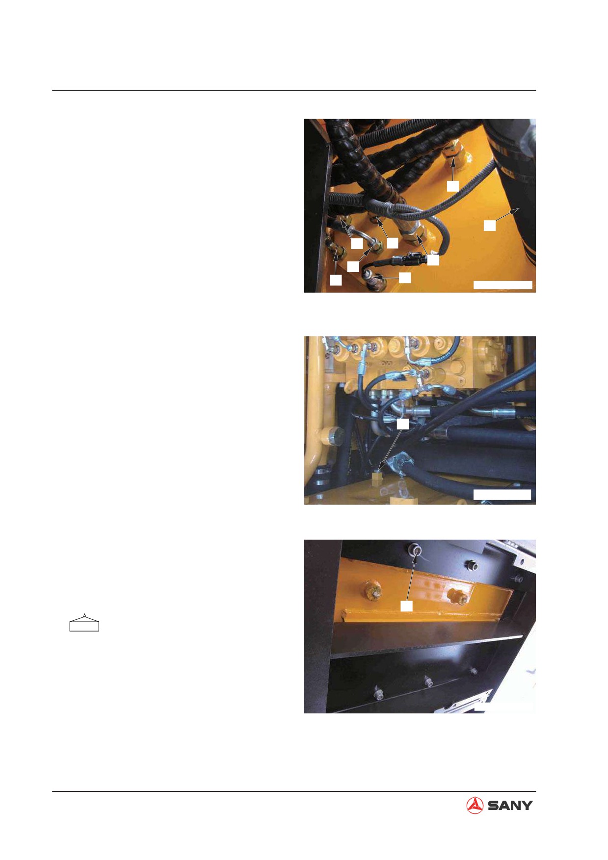
8. Disconnect the seven hoses.
Ɣ (11): Oil return - pilot T block
Ɣ (12): Oil return - main pump
17
Ɣ (13): Oil return D2 - main valve
Ɣ (14): Sensor - temperature
18
Ɣ (15): Oil return - solenoid valve
15
11
Ɣ (16): Oil return D1/D3 - main valve
12
13
16
14
Ɣ (17): Oil return - swing motor
ZX215T-1006125
NOTE:
Ɣ Disconnect the oil inlet hose (18) from the
hydraulic tank after disconnection of the oil
inlet tube from the pump.
Ɣ Attach each hose with an identification tag.
Ɣ Use a sleeve nut to prevent the fitting and
the cone seal from damage.
19
9. Remove the hose clamp (19).
ZXT225-1106008
10. Lift the hydraulic tank assembly and re-
move the six bolts (20).
11. Lift off the hydraulic tank assembly for dis-
assembling.
20
Hydraulic tank assembly: 130 kg
ZX215T-1006127
8-78
Disassembly and Assembly
8.21.2 Installation
Ɣ Installation is to be performed in the re-
verse order of removal.
Screw
Drain plug (hydraulic tank):
58.8~78.5 N·m {6.0~8.0 kgf·m}
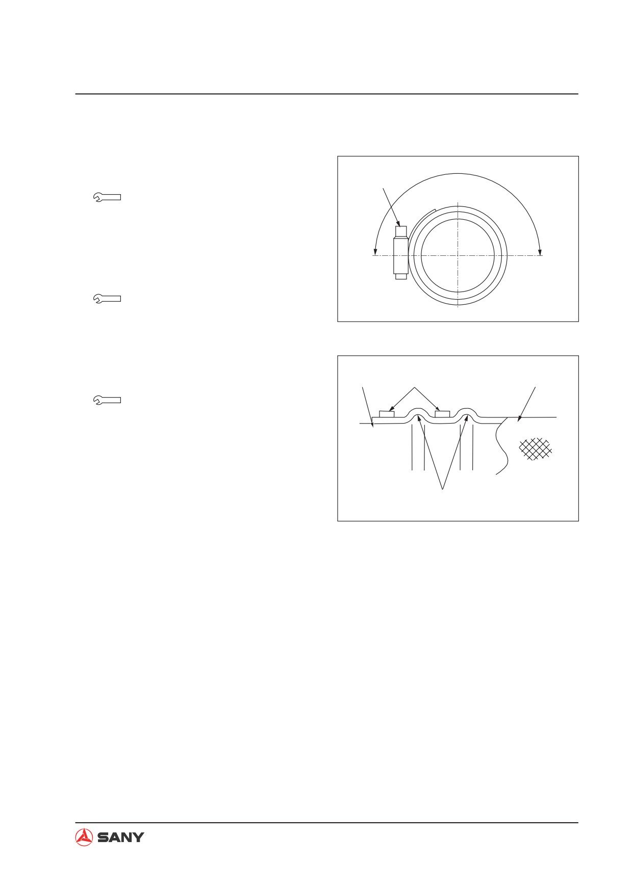
NOTE: After tightening the hose clamping
Up
screw, check that the screw should be in
Down
the range indicated in the illustration.
Screw (hose clamp):
ZX215-1006128
8.8±0.5 N·m {0.9±0.05 kgf·m}
Ɣ Install the hose clamp and tighten the
screw according to the illustration on
the right.
Pipe
Clamp
Hose
Bolt:
245.2~308.9 N·m {25~31.5 kgf·m}
Ɣ Oil adding (hydraulic tank)
Bulge
Add hydraulic oil through the filler opening
ZX215-1006129
to the specified level. Start the engine to
circulate oil in the hydraulic system, and
check the oil level again.
Ɣ Air bleeding
For more information, see “Air in Each
Component - Bleed” on page 6-46.
8-79
Disassembly and Assembly
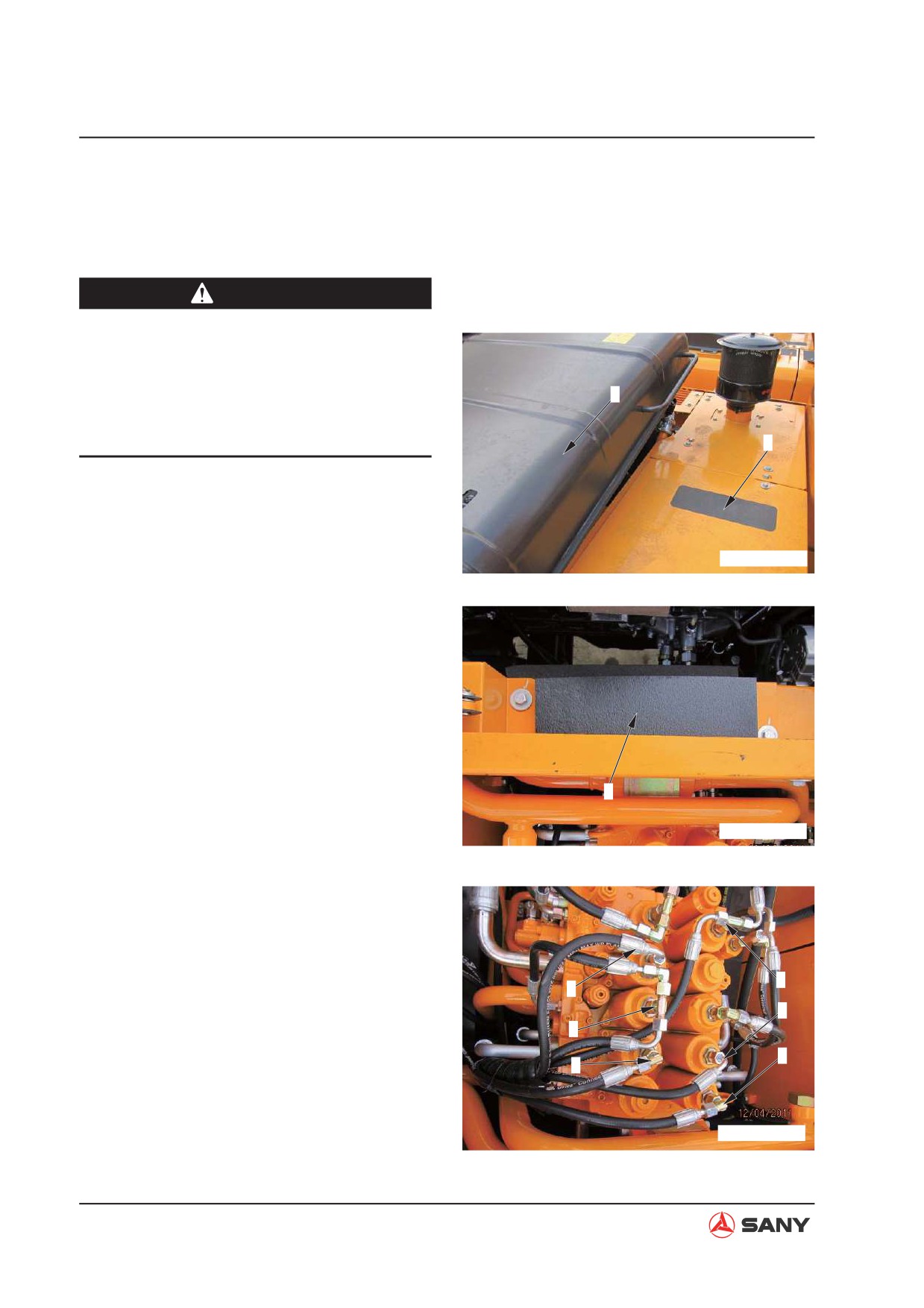
8.22 Control Valve AS - Remove and Install
8.22.1 Removal
WARNING
Ɣ Lower the work equipment to the
ground. Stop the engine. Press the re-
lease button of the breather valve to re-
lease residual pressure in the hydraulic
1
tank. Place the hydraulic lockout con-
trol in the LOCK position.
2
NOTE: Tag each line so as to ensure correc-
tion installation.
ZXT225-1106009
1. Lift the hood (1).
2. Remove the cover (2) above the control
valve.
3. Remove the engine silencing hood (3).
3
ZXT225-1106010
4. Remove the baffle (4) to (9) of the pres-
sure transducer and tag them.
(4): XAK Bucket DIG
7
(5): XBb1 Boom DOWN
4
8
(6): XAtL Travel LEFT
5
(7): XBa1 Arm IN
9
6
(8): XBs Swing RIGHT
(9): XAtr Travel RIGHT
ZXT225-1106011
8-80
Disassembly and Assembly
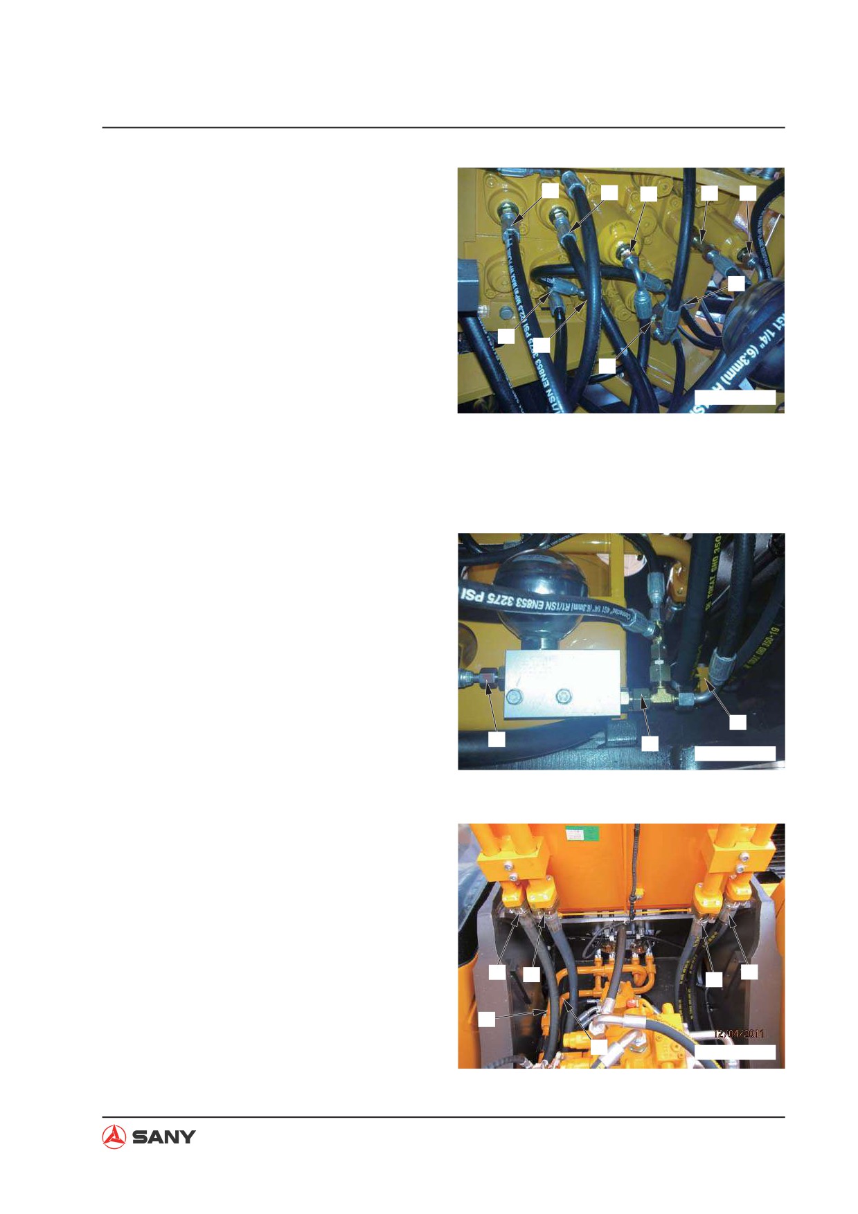
5. Disconnect the pilot hoses (10) to (18) and
10
11
13
14
tag them properly.
12
(10): XBtr Travel RIGHT
(11): XAs Swing LEFT
18
(12): PSP Swing priority
(13): XAa1 Arm OUT
15
16
(14): XBp2 Bucket confluence
17
(15): XBtL Travel LEFT
ZXT225-1106012
(16): XAb1 Boom UP
(17): XBK Bucket DIG
(18): XAa2 Arm OUT
6. Remove the port (19) (accumulator to
solenoid valve), port (10) (pilot filter to ac-
cumulator). Remove hose clip (21) of the
central swivel joint.
21
19
20
ZXT225-1106013
7. Remove bucket hoses (22) and (23) and
seal the ports.
8. Remove arm hoses (24) and (25) and seal
the ports.
9. Remove boom hoses (26) and (27) and
seal the ports.
22
24
23
25
26
27
ZXT225-1106014
8-81
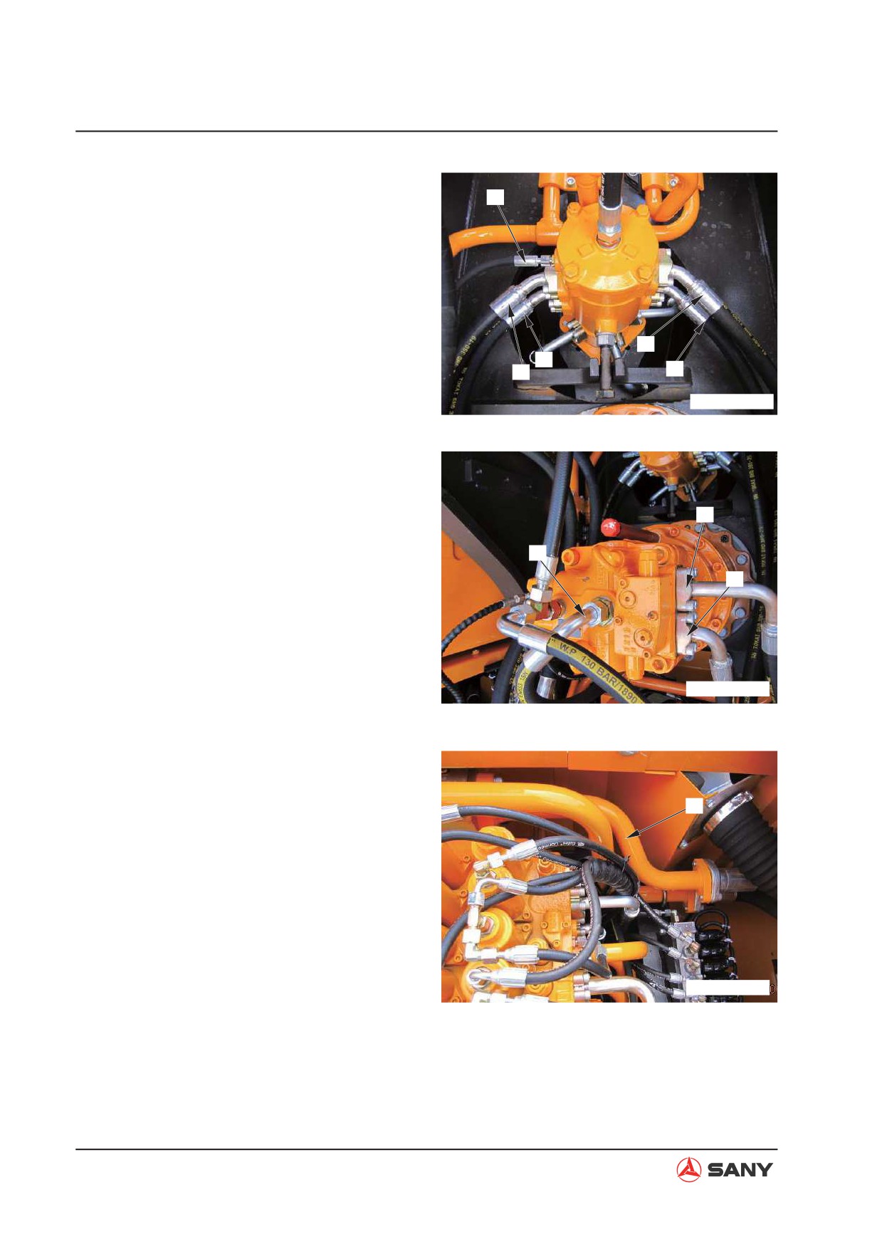
Disassembly and Assembly
10. Remove central swivel joint hoses (28),
32
(29), (30) and (31). Remove travel speed
switching hose (32) and seal the ports.
30
29
28
31
ZXT225-1106015
11. Remove swing motor hoses (33) and (34).
Remove swing motor oil complement hose
(35). Seal the ports properly.
33
35
34
ZXT225-1106016
12. Remove pipe (36) (main valve to radiator).
36
ZXT225-1106017
8-82
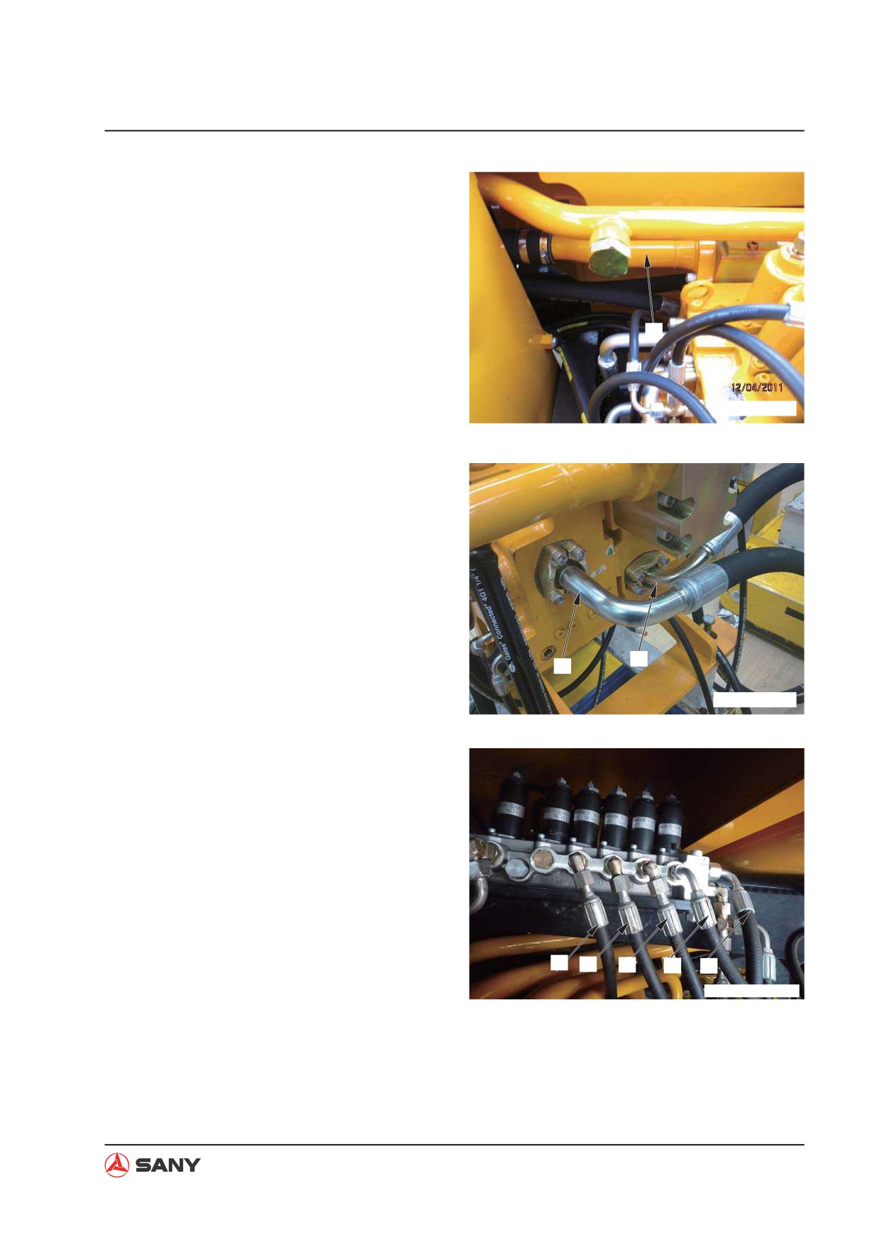
Disassembly and Assembly
13. Remove pipe (37) (main valve to return oil
tank). Seal the ports properly.
37
ZXT225-1106018
14. Remove hydraulic pump hoses (38) and
(39).
39
38
ZXT225-1106019
15. Remove hoses (40) to (44) on the solenoid
valve and tag them properly.
(40): PPC lockout valve
(41): Main valve PnA2
(42): Main valve XBP2
(43): Main valve PSP
(44): Travel PT port
40
41
42
43
44
WXT215-1208001G
8-83
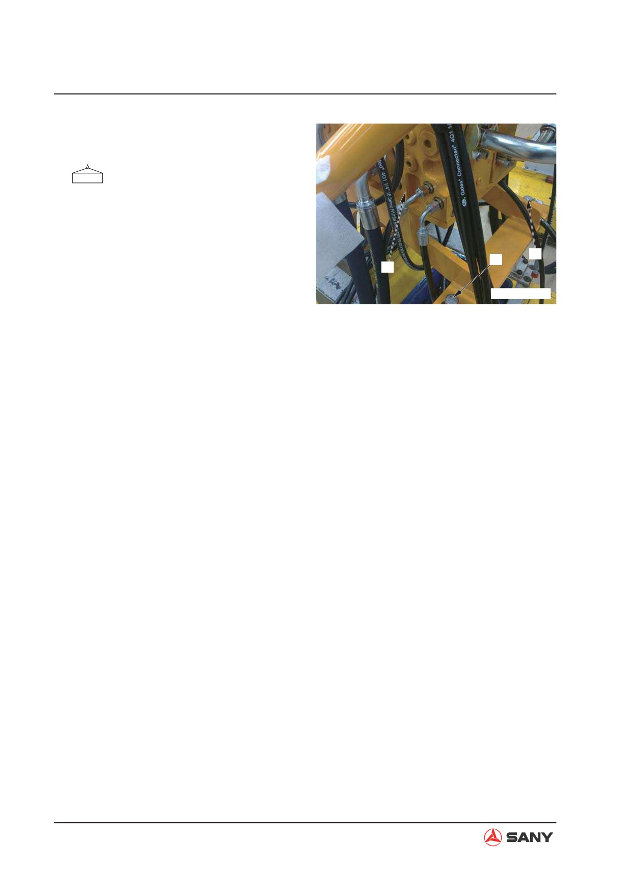
Disassembly and Assembly
16. Remove the fixing bolts (45). Lift the con-
trol valve assembly (46) for disassembling.
Control valve assembly: 220 kg
45
45
46
ZXT225-1106021
8.22.2 Installation
Ɣ Installation is to be performed in the re-
verse order of removal.
Ɣ Oil adding (hydraulic tank)
Add hydraulic oil through the filler opening
to the specified level. Start the engine to
circulate oil in the hydraulic system, and
check the oil level again.
Ɣ Air bleeding
Bleed the air from the circuit between the
valve and the hydraulic cylinder.
For more information, see “Air in Each
Component - Bleed” on page 6-46.
8-84
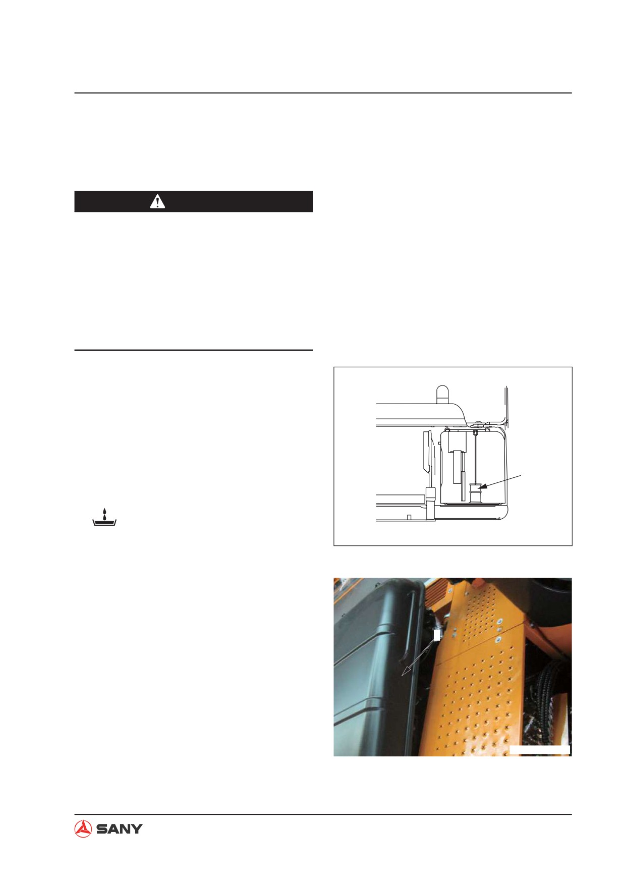
Disassembly and Assembly
8.23 Hydraulic Pump AS - Remove and Install
8.23.1 Removal
WARNING
Ɣ Lower the work equipment to the
ground and stop the engine. Press the
release button of the breather valve to
release residual pressure in the hydrau-
lic tank.
Ɣ Disconnect the cable from the negative
(-) post of the battery before performing
the job.
NOTE: Tag each line so as to ensure correc-
tion installation.
1. Remove the oil inlet filter element from the
hydraulic tank and stop oil outflow with an
oil stopper.
NOTE: If no oil stopper is used, remove
Oil stopper
the drain plug and drain the oil from the
hydraulic tank and from circuits.
Hydraulic tank: Approx. 225 L
ZX215-1006144
2. Lift the hood (1).
1
ZX215T-1006145
8-85
Disassembly and Assembly
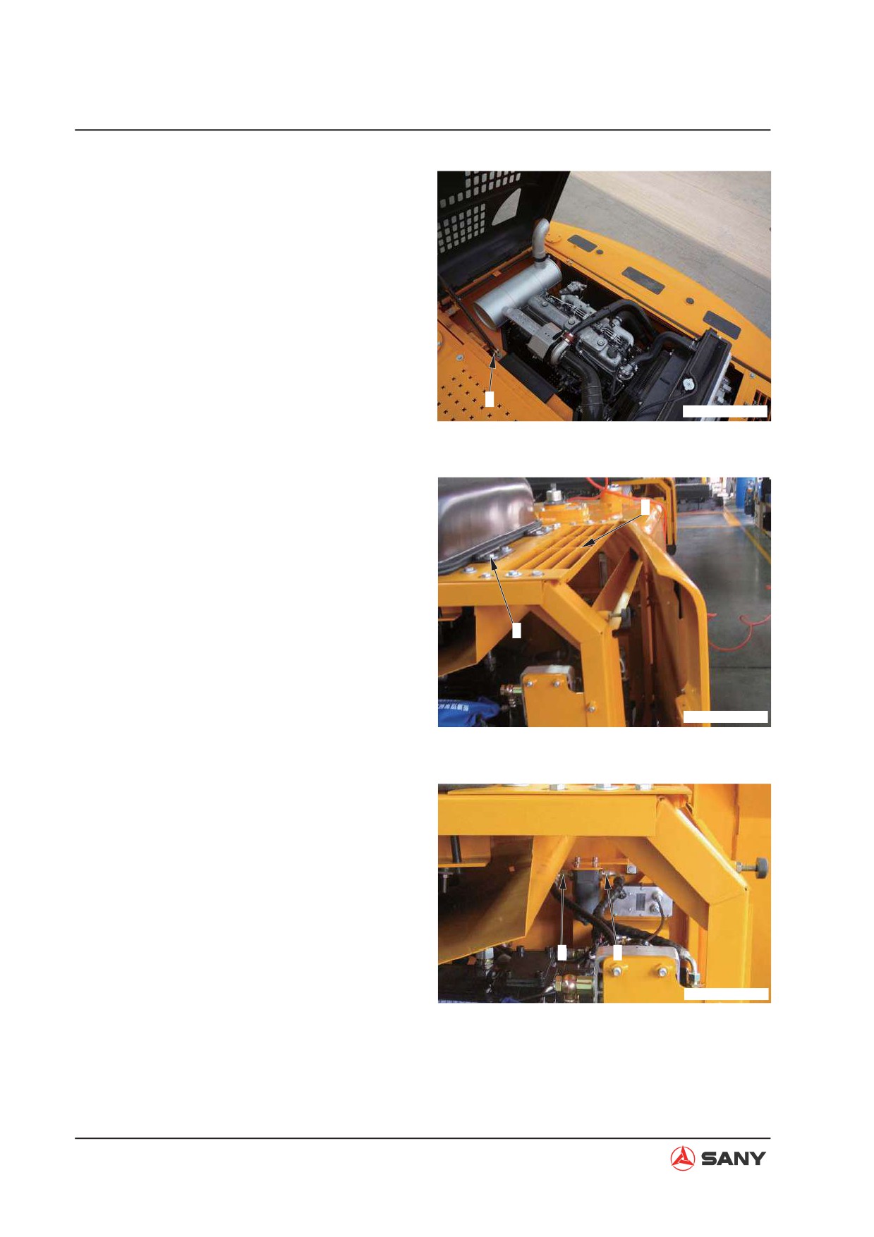
3. Remove the pin (2) and the bolts (3). Lift
the engine hood in order to remove it.
2
ZX215T-1006146
4. Remove the right upper cover (4).
4
3
ZX215T-1006147
5. Disconnect the hose (5) supplying oil to the
lower proportional valve and the hose (6)
delivering oil from the pilot pump.
5
6
ZX215T-1006148
8-86
Disassembly and Assembly
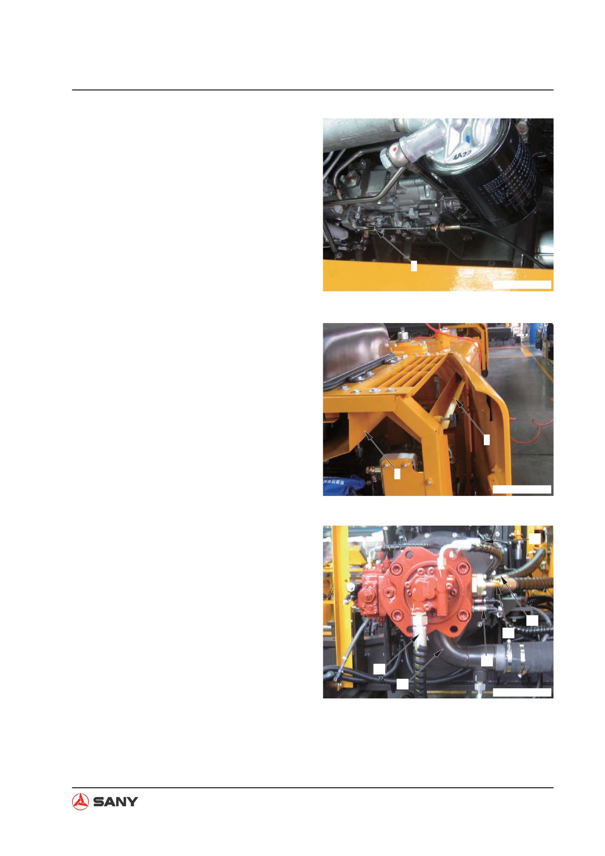
6. Disconnect the shutdown wire (7).
7
ZX215T-1006149
7. Remove the right door (8).
8. Remove the hydraulic pump cover (9).
8
9
ZX215T-1006150
9. Disconnect the oil drain hose (10) and seal
10
the openings properly.
10. Disconnect the high-pressure hoses (11)
and (12) connecting to the control valve,
and seal the openings properly.
11. Disconnect the harness (13) of the pres-
12
sure transducer.
11
12. Disconnect the pilot pump oil inlet hose (14)
13
and seal the openings properly.
14
15
ZX215T-1006151
13. Disconnect the pilot pump oil inlet tube (15)
and seal the openings properly.
8-87
Disassembly and Assembly
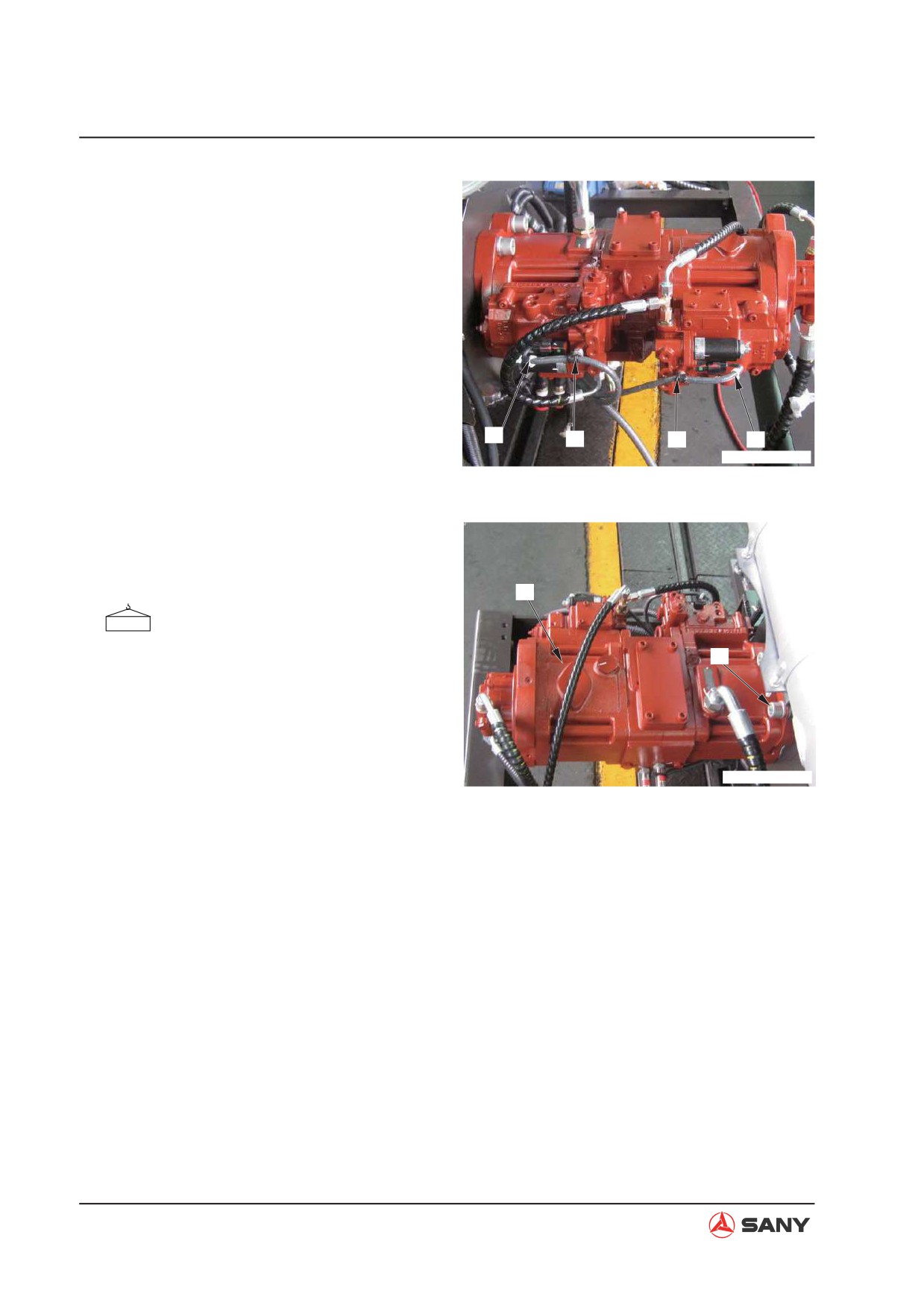
14. Disconnect the solenoid valve harnesses
(16) and (17). Remove the cable straps (18)
and (19).
16
18
19
17
ZX215T-1006152
15. Remove the four bolts (20) of the hydraulic
pump. Lift the hydraulic pump assembly
(21) to remove it.
21
Hydraulic pump assembly: 112 kg
20
ZX215T-1006153
8-88
Disassembly and Assembly
8.23.2 Installation
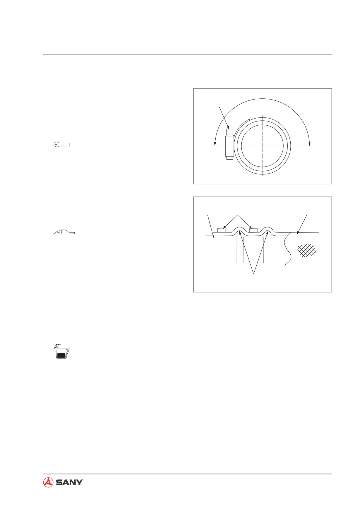
Ɣ Installation is to be performed in the re-
verse order of removal.
Screw
NOTE: After tightening the hose clamping
screw, check that the screw should be in
the range indicated in the illustration.
Up
Screw (hose clamp):
Down
8.8±0.5 N·m {0.9±0.05 kgf·m}
ZX215-1006128
Ɣ Install the hose clamp and tighten the
screw according to the illustration on
Pipe
Clamp
Hose
the right.
Mating surface (hydraulic pump
housing):
Gasket sealant: (Loctite 515)
Bulge
ZX215-1006129
Ɣ Oil adding (hydraulic tank)
Add hydraulic oil through the filler opening
to the specified level. Start the engine to
circulate oil in the hydraulic system, and
check the oil level again.
Hydraulic tank: approx. 225 L
Ɣ Air bleeding
For more information, see “Air in Each
Component - Bleed” on page 6-46.
8-89