Rexroth: Screw Assemblies. Catalog (R999001185/2020-03) - page 17
244
Screw Assemblies | Planetary Screw Assemblies PLSA
Accessories
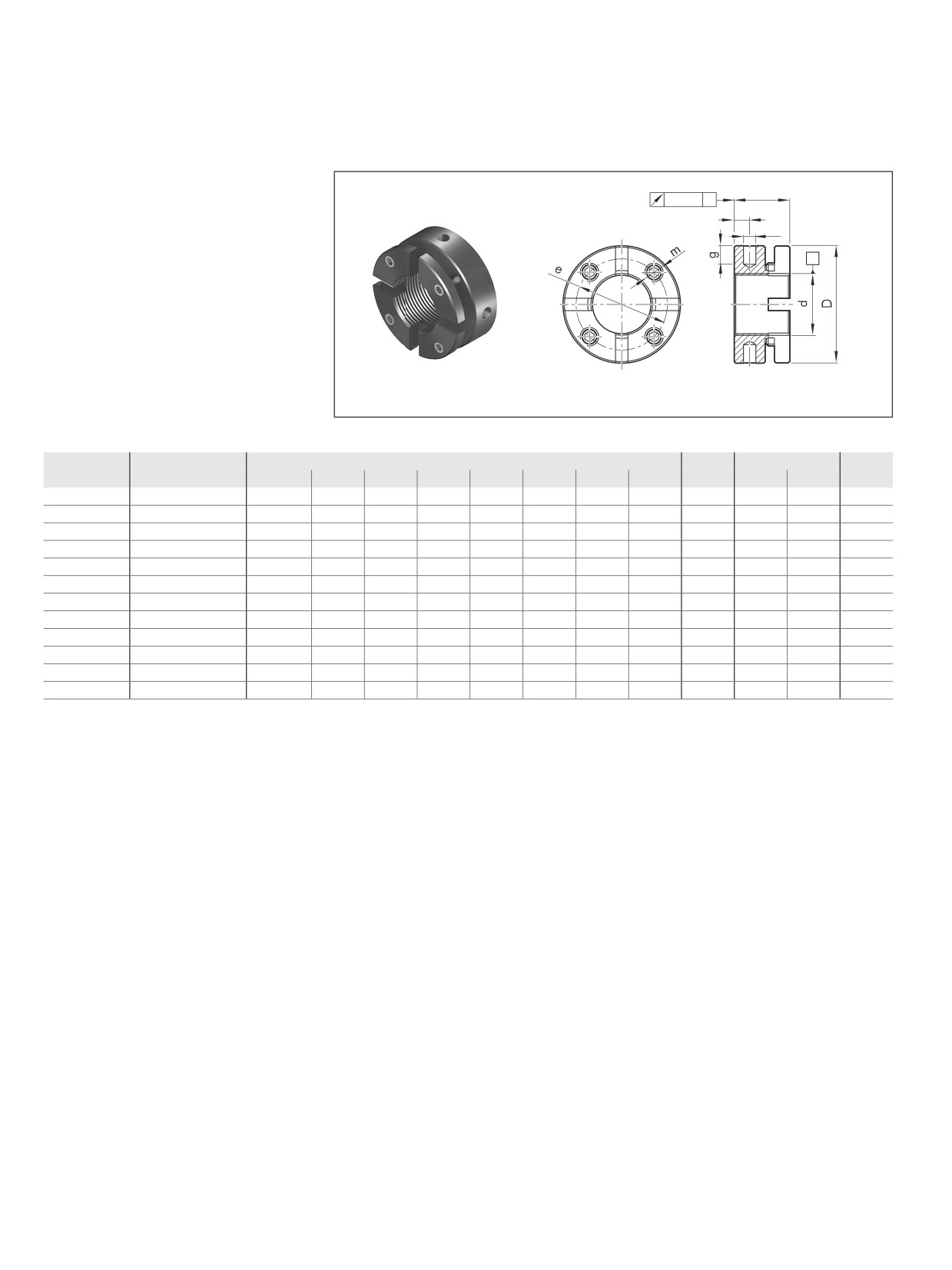
Slotted nuts NMA for fixed bearings
Slotted nut NMA
B
0,005
A
C
--
For maximum vibratory loads
f
-–
NMA 15 to 40 with 4 segments
-–
NMA 45 to 90 with 6 segments
A
Abbreviation
Part number
(mm)
MA
FaB
MAG
Mass
d
D
B
c
m
e
f
g
(Nm)
(kN)
(Nm)
m (g)
NMA 15x1
R3446 020 04
M15x1
30
18
5
M5
24
4
5
10
100
3
60
NMA 17x1
R3446 014 04
M17x1
32
18
5
M5
26
4
5
15
120
3
70
NMA 20x1
R3446 015 04
M20x1
38
18
5
M6
31
4
6
18
145
5
130
NMA 25x1.5
R3446 011 04
M25x1.5
45
20
6
M6
38
5
6
25
205
5
160
NMA 30x1.5
R3446 016 04
M30x1.5
52
20
6
M6
45
5
7
32
250
5
200
NMA 35x1.5
R3446 012 04
M35x1.5
58
20
6
M6
51
5
7
40
280
5
230
NMA 40x1.5
R3446 018 04
M40x1.5
65
22
6
M6
58
6
8
55
350
5
300
NMA 45x1.5
R9130 342 15
M45x1.5
70
22
6
M6
63
6
8
65
360
5
340
NMA 50x1.5
R3446 019 04
M50x1.5
75
25
8
M6
68
6
8
85
450
5
430
NMA 60x2
R9130 342 16
M60x2.0
90
26
8
M8
80
6
8
100
550
15
650
NMA 70x2
R9130 342 17
M70x2.0
100
28
9
M8
90
8
10
130
650
15
790
NMA 90x2
R9163 113 51
M90x2.0
130
32
13
M10
118
8
10
200
900
20
1.530
For the codes, see the chapter entitled “Abbreviations”
Planetary Screw Assemblies PLSA |
245
Accessories
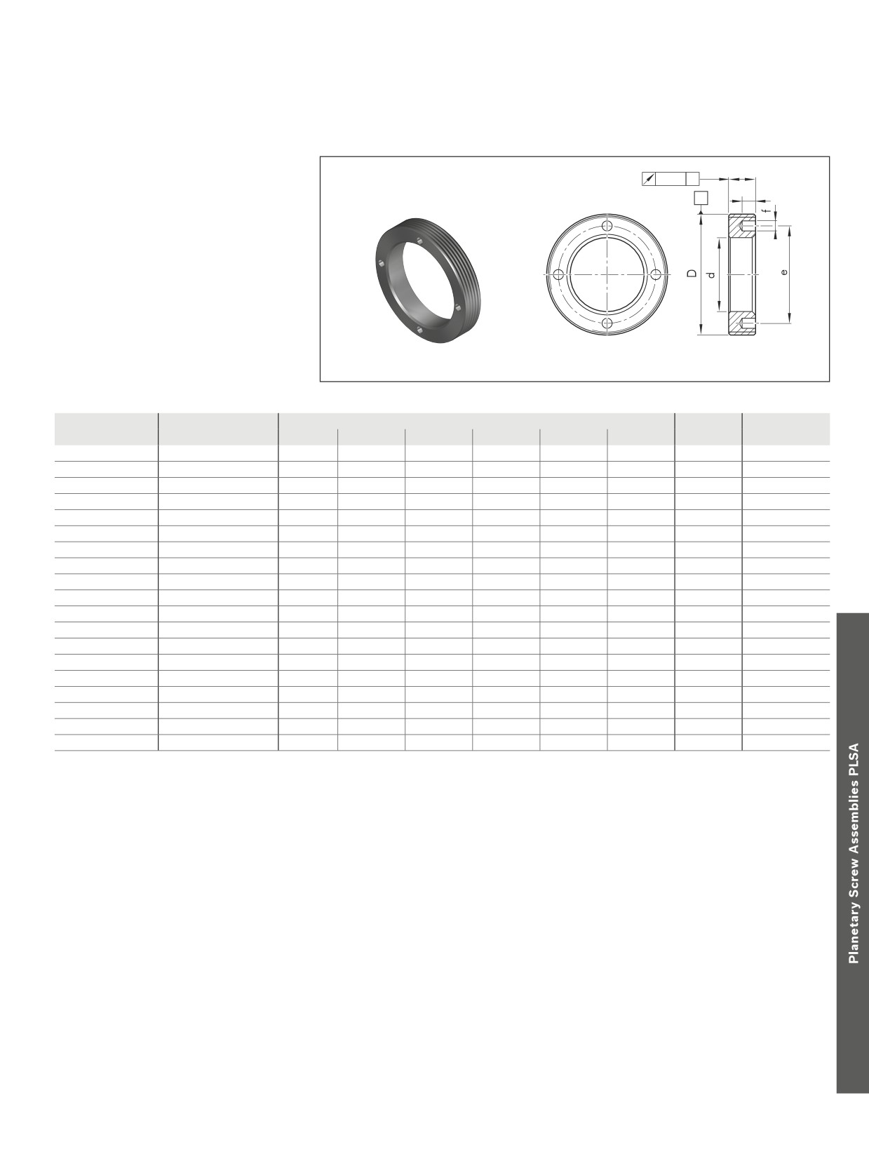
Ring nut GWR
--
For angular-contact thrust ball bearing LGN
B
0,01
A
g
A
Attention:
Use a threadlocker (for example,
Loctite 638) to secure against loosening
MA = Tightening torque for Threaded Ring
Abbreviation
Part number
(mm)
MA
Mass
D
d
B
e
f
g
(Nm)
m (g)
GWR 18x1
R1507 040 33
M18x1
8.5
8
12.5
2.5
3
6
10.0
GWR 23x1
R1507 240 35
M23x1
13.0
8
18.0
2.5
3
8
15.0
GWR 26x1,5
R1507 240 22
M26x1.5
16.5
8
20.5
2.5
3
10
16.5
GWR 30x1,5
R1507 340 34
M30x1.5
17.0
8
23.0
3.0
4
20
29.0
GWR 36x1,5
R1507 040 23
M36x1.5
22.0
8
29.0
3.0
4
25
35.0
GWR 40x1,5
R1507 140 03
M40x1.5
25.0
8
33.0
3.0
4
28
39.5
GWR 45x1,5
R1507 240 04
M45x1.5
28.0
8
38.0
3.0
4
30
55.0
GWR 50x1,5
R1507 240 25
M50x1.5
31.0
10
40.0
4.0
5
45
86.0
GWR 55x1,5
R1507 340 05
M55x1.5
36.0
10
46.0
4.0
5
50
96.0
GWR 58x1,5
R1507 440 32
M58x1.5
43.0
10
50.0
4.0
5
58
84.0
GWR 60x1
R1507 440 28
M60x1
43.0
10
51.0
4.0
5
60
97.0
GWR 62x1,5
R1507 440 29
M62x1.5
43.0
12
53.0
5.0
6
60
127.0
GWR 65x1,5
R1507 440 26
M65x1.5
47.0
12
55.0
4.0
5
70
136.0
GWR 70x1,5
R1507 440 06
M70x1.5
42.0
12
58.0
4.0
5
75
216.0
GWR 78x2
R1507 567 27
M78x2
54.0
15
67.0
6.0
7
90
286.0
GWR 92x2
R1507 640 09
M92x2
65.0
16
82.0
6.0
7
125
385.0
GWR 95x2
R1507 667 28
M95x2
68.0
16
82.0
6.0
7
130
425.0
GWR 112x2
R1507 740 11
M112x2
82.0
18
100.0
8.0
8
175
596.0
GWR 115x2
R1507 767 29
M115x2
85.0
18
100.0
8.0
8
200
664.0
246
Screw Assemblies | Planetary Screw Assemblies PLSA
Accessories
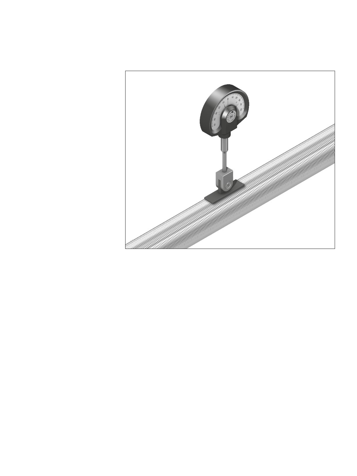
Measuring pads
Alignment of the Planetary Screw
Assembly in the machine
Rexroth can provide a gauge with a
self-aligning contact pad for easy alignment
of the Planetary Screw Assembly.
Two pads of different lengths are available
which can be used depending on the screw
lead:
--
material no. R3305 131 19:
length 33 mm
--
material no. R3305 131 21:
length 50 mm
Dial gauge not supplied as standard with the Planetary Screw Assembly
Planetary Screw Assemblies PLSA |
247
Accessories
248
Screw Assemblies | Planetary Screw Assemblies PLSA
Technical data
Technical notes
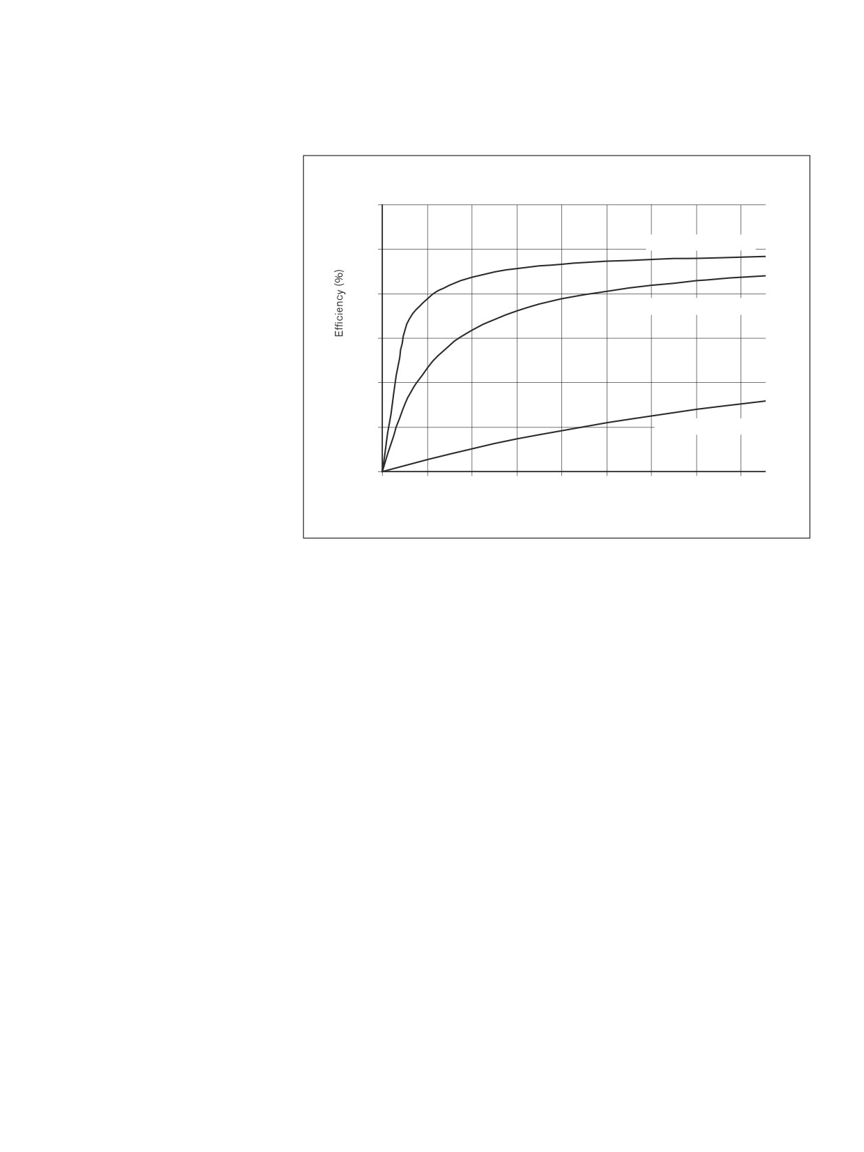
The degree of efficiency determines the
torque required to convert the rotary motion
into linear motion.
120
Due to their high mechanical efficiency,
Ball Screw Assembly
PLSAs are in principle not self-locking.
100
cc
Safety information
For installation, customers should check
80
Planetary Screw Assembly
whether separate protection against falling
loads is required.
60
Please consult us.
40
20
Acme screw
0
0
1
2
3
4
5
6
7
8
Lead angle (°)
--
The maximum mechanical efficiency of
--
Less drive power required
Advantages over the Acme screw drive
an Acme screw drive is 50%, whereas a
-–
No stick-slip effect
Planetary Screw Assembly can achieve
-–
More precise positioning
90%, and a Ball Screw Assembly 98%.
-–
Higher travel speed
--
Higher life expectancy due to negligible
--
Less heat-up
wear during operation
Selection criteria for Planetary Screw
The factors below should be considered
Assemblies (extract)
when selecting the PLSA for a given appli-
cation:
-- buckling load
--
degree of accuracy required
-–
rigidity/permissible clearance or desired
(lead deviation)
preload
-- Load
--
characteristic speed (max. permissible
-– Service life
linear speed)
-– critical speed
cc
Note
Radial and eccentric forces relative to the screw must be avoided, as they can affect the PLSA’s performance and shorten its life.
Where special conditions of use are involved, please consult us.
The following points should be taken into consideration when selecting a PLSA that is to be both cost-efficient and optimally designed:
--
The calculation of the service life should be based on average loads and average speeds, not on maximum values.
-–
In order for us to provide you with a customized solution, installation drawings or sketches of the nut environment should be enclosed.
Planetary Screw Assemblies PLSA |
249
Technical data
Static load rating C0
The static load rating is an axial, concentrically acting force that induces a permanent defor-
mation of 0.0001 x the rolling element diameter.
Dynamic load rating C
The dynamic load rating is an axial, concentrically acting force of constant magnitude and
direction under which 90% of a sufficiently large number of identical PLSAs can achieve a
nominal service life of one million revolutions.
Correction factor for tolerance grades
The static load rating C0 and the dynamic load rating C must be multiplied by the correction
factor fac as appropriate for the specific tolerance grade of the screw.
Tolerance grade T
5
7
9
fac
1
0.9
0.8
Service life
The nominal service life is expressed by the number of revolutions (or number of operating
hours at constant speed) that will be attained or exceeded by 90% of a representative
sample of identical Planetary Screw Assemblies before the first signs of material fatigue
become evident. The nominal life is designated as L or Lh h, depending on whether it is
specified in revolutions or hours.
The nominal life calculation is based on optimal installation and environmental conditions.
The service life may be shortened, for example, if the lubrication is affected by exposure to
process media.
Critical speed and buckling load
The critical speed and buckling load can be checked using the corresponding charts. For
precise calculations
see formula 12
15 , in the section “Design Calculations”
Characteristic speed
d0 · n
Rexroth PLSAs can be operated at very high speeds due to their structural design. Charac-
teristic speeds of up to 150,000 are possible depending on the nut type. The characteristic
speeds can be exceeded for short periods, please consult us.
d0 · n
≤
150,000
d0
=
nominal diameter
(mm)
n
=
speed
(rpm)
The theoretically possible maximum linear speed vmax (m/min) is specified on the page
featuring the relevant nut. Actually attainable speeds are heavily dependent among other
factors on preload and duty cycle. They are generally restricted by the critical speed.
(See “Design Calculations”).
Material, hardness
PLSA's are made of high-quality, heat-treatable steel, carbon chrome alloy steels or
case-hardened steels. The screw and nut raceways have a minimum Rockwell hardness of
HRC 58. The screw ends are not hardened.
250
Screw Assemblies | Planetary Screw Assemblies PLSA
Technical data
Technical notes
Sealing
PLSAs are precision assemblies that require protection against contamination. Flat protec-
tive covers, bellows-type dust boots or other enclosures are particularly suitable for this
purpose. As there are some applications in which these methods do not provide sufficient
protection, we have developed an additional gapless lip-type seal which ensures an optimal
sealing effect and maintains high efficiency due to the low friction level. Our PLSAs can
therefore be supplied with lip-type seals as an option.
At the customer’s request, the seals can be omitted entirely.
To ensure that seals retain their functionality, dirt must be removed at regular intervals.
Short stroke
Lubrication:
Short stroke applications = stroke ≤ nut
During a short stroke, the planets do not make a real turn. It is therefore impossible for an
length
adequate lubricating film to form. This may result in premature wear.
To avoid this, it is sufficient to perform longer strokes at regular intervals with simultaneous
relubrication as “lubricating strokes”.
Load rating:
Short stroke applications will increase the number of times a rolling load passes over each
point within the load zone.
This reduces the load rating.
Please consult us.
Permissible operating temperatures
Standard design PLSAs allow a continuous temperature of 60 °C (measured on the outer
shell of the nut).
Permissible operating temperatures:
-10 °C ≤ Toperation ≤ 60 °C
Permissible bearing temperatures:
-15 °C ≤ Tbearing ≤ 80 °C
Applications with high-loading and/or rapid cycles can generate excessive heat. To prevent
excessive heating, Bosch Rexroth recommends cooling the screw and/or the nut. Apart
from this, we can offer solutions for uses at higher temperatures.
Bearing
When calculating the life expectancy of the overall system, the end bearings must be
considered separately.
Planetary Screw Assemblies PLSA |
251
Technical data
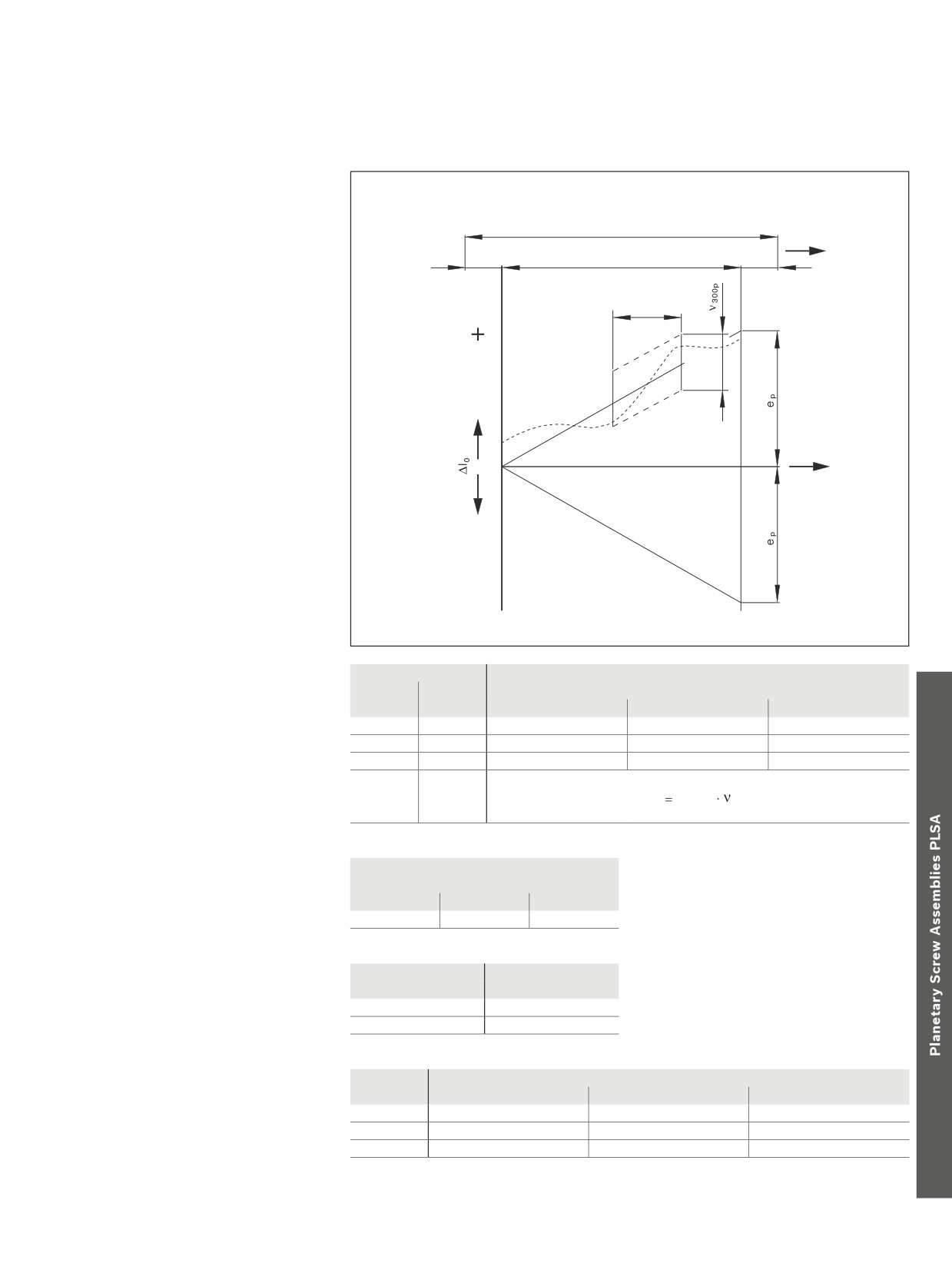
Acceptance Conditions and Tolerance Grades
Permissible travel deviation
PLSA with precision screw PSR
T
based on DIN ISO 3408-3
l 1
l 0
Symbol definitions:
le
l u
le
(excerpt)
l0
= nominal travel
l1
= thread length
300
∆l0
= travel deviation
lu
= Useful travel
le
= excess travel (the closer tolerances for
travel and hardness do not apply here)
c
= travel compensation (target travel
deviation) (standard: c = 0)
ep
= tolerance mean target travel deviation
ν300p = permissible travel deviation within
300 mm travel
ν2πp
= permissible travel deviation within one
revolution
c = 0
Useful travel lu
Tolerance mean actual travel deviation ep (µm)
Tolerance grade
>
≤
5
7
9
0
100
18
44
110
100
200
20
48
120
200
315
23
52
130
315
lu
ep
300p
300
ν300p (µm)
For precision screws PSR the following
Tolerance grade
values apply in all cases:
5
7
9
23
52
130
d0
le
Non-usable length le
(mm)
(mm)
(Excess travel)
20, 25, 30, 39
40
48, 60, 75
50
Lead P
Minimum number of measurements for tolerance grade
Minimum number of measurements within
(mm)
5
7
9
300 mm (measuring interval) and excess
5
6
3
3
travel to be taken into consideration.
10
3
1
1
20
3
1
1
252
Screw Assemblies | Planetary Screw Assemblies PLSA
Technical data
Acceptance Conditions and Tolerance Grades
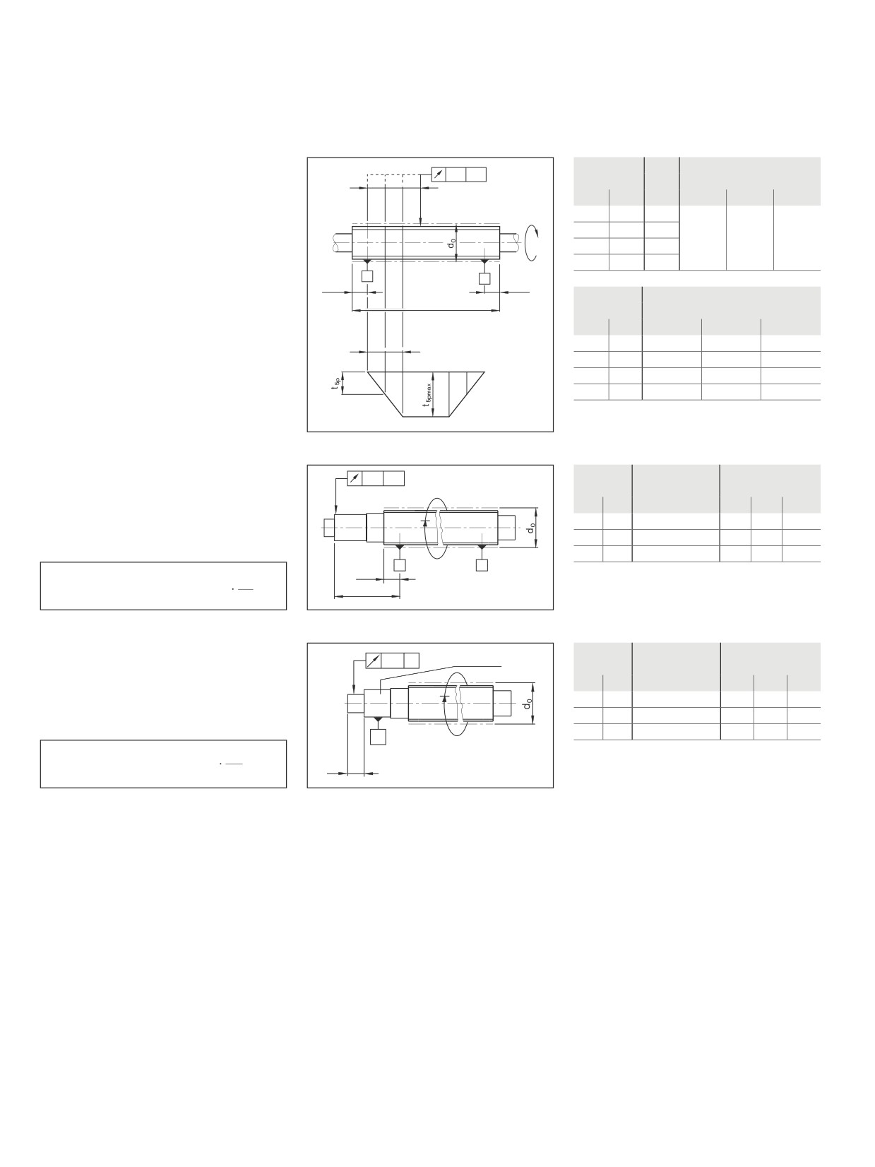
d0
l5
t5pmax in µm for l5
Run-outs and location deviations
t
5p
AA'
l5
l5
l5
Tolerance grade
based on DIN ISO 3408-3
>
≤
5
7
9
6
12
80
32
40
60
Radial run-out t5 of the outer diameter of
12
25
160
the screw over the length l5 used to deter-
25
50
315
mine the straightness in relation to AA’.
50
100
630
A
A'
2
d 0
2 d 0
l1/d0
t5pmax in µm for l1 ≥ 4l5
l 1
Tolerance grade
>
≤
5
7
9
l
5
l
5
40
64
80
120
40
60
96
120
180
A
A
60
80
160
200
300
80
100
256
320
480
d0
Reference
t6p in µm for l6 ≤ l
Coaxial deviation t6
of the bearing journal in
t
6p
AA'
length l
Tolerance grade
relation to AA' where l6 ≤ l.
>
≤
5
7
9
Tabular value t6p applies if I6 ≤ reference
6
20
80
20
40
50
length I.
20
50
125
25
50
63
50
125
200
32
63
80
A
A'
2 d 0
l6
Where l6
> l, then
t 6a ≤ t
l6
6p
l
d0
Reference
t7p in µm for l7 ≤ l
Coaxial deviation t7 of the journal diame-
t
Bearing seat
C
7p
length l
Tolerance grade
ter of the screw in relation to the bearing
>
≤
5
7
9
diameter for l7 > l.
6
20
80
8
12
14
Tabular value t7p applies if I7 ≤ reference
20
50
125
10
16
18
length I.
50
125
200
12
20
23
C
l7
d0
= nominal diameter
t 7a ≤ t
Where l7 > l, then
7p
l 7
l
Planetary Screw Assemblies PLSA |
253
Technical data
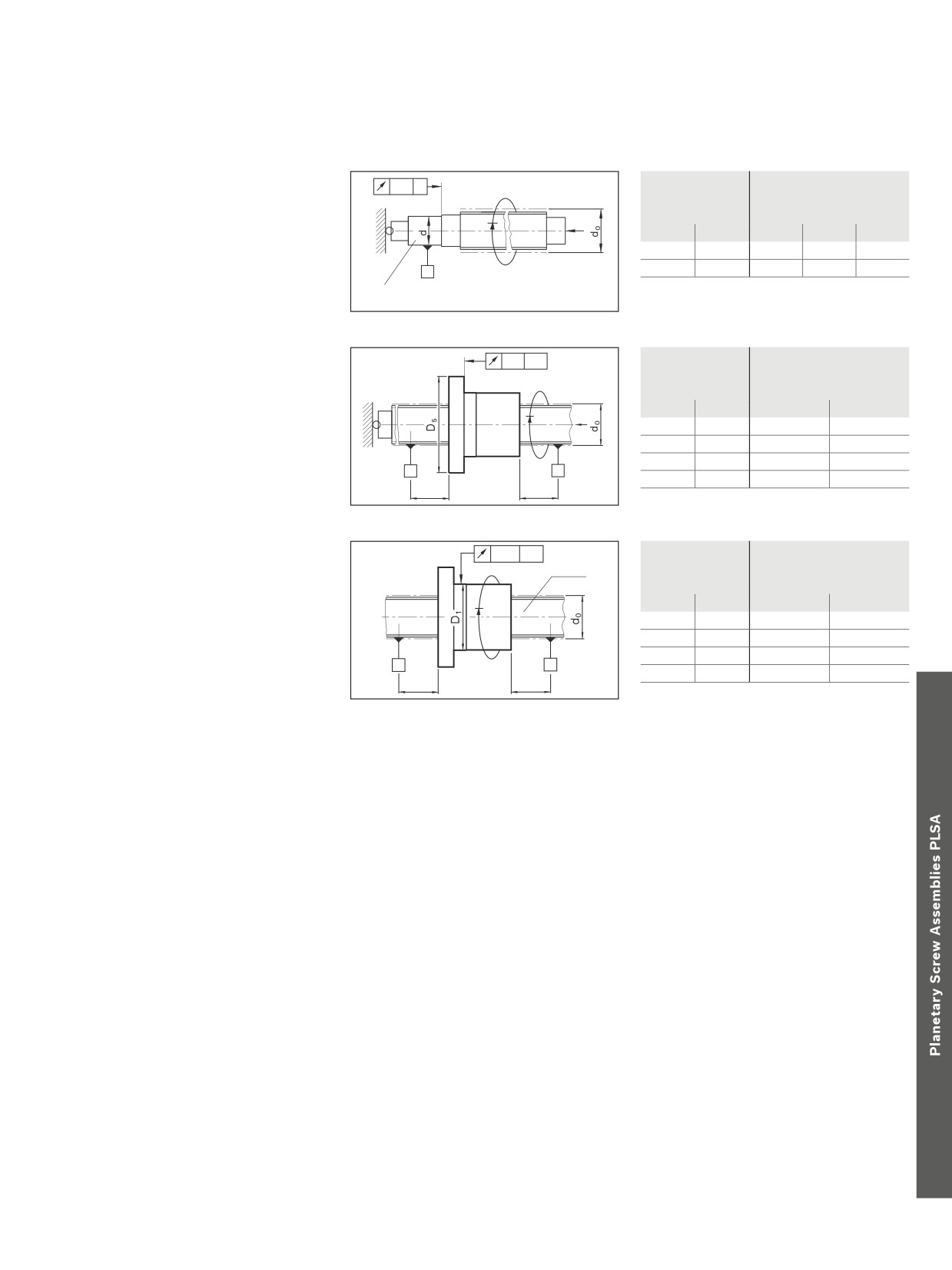
d0
t8p in µm
Axial run-out t8
of the shaft (bearing) face of
t
C
8p
for tolerance grade
the screw in relation to the bearing diameter.
F
>
≤
5
7
9
6
63
5
6
8
63
125
6
8
10
C
Bearing seat
Flange diameter
t9p in µm
Axial run-out t9
of the nut location face
t9p
AA'
D5
for tolerance grade
in relation to A and A' (for preloaded ball
nuts only).
>
≤
5
7
F
16
32
16
20
32
63
20
25
63
125
25
32
A
A'
125
250
32
40
2 d0
2 d0
Outer diameter
t10p in µm
Radial run-out t10 of the outer diameter D1
t10p
AA'
fixed
D1
for tolerance grade
of the nut unit in relation to A and A' (for
preloaded and rotating nuts only). Fix screw
>
≤
5
7
to prevent rotation before carrying out the
16
32
16
20
measurement.
32
63
20
25
63
125
25
32
A
A'
125
250
32
40
2 d0
2 d0
254
Screw Assemblies | Planetary Screw Assemblies PLSA
Technical data
Preload, Rigidity, Friction Torques
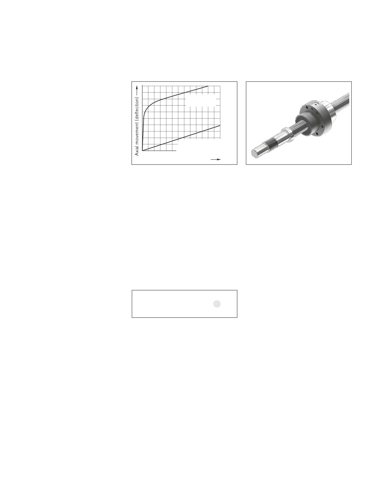
Nut system preload
In addition to single nuts with reduced backlash, Rexroth supplies preloaded nut systems.
Single nut with
backlash
Preloaded and adjustable-
preload nut systems
Axial load
With preloaded nut systems, the deformation due to load cycling is significantly less than
that of systems without preload.
Preloaded nut systems should therefore be used in applications requiring a high degree of
rigidity.
The preload of the Planetary Screw Assembly will decrease over time as a function of the
load and the operating hours.
The screw is typically far less rigid than the nut unit (for details see “Overall axial rigidity...”).
Rigidity
The rigidity of a Planetary Screw Assembly is also influenced by all adjoining parts such as
bearings, housing bores, nut housings etc.
Overall axial rigidity Rbs of the
The overall axial rigidity Rbs is made up of the component rigidity of the bearing Rfb, the
Planetary Screw Assembly
screw RS and the nut unitRnu.
1
1
1
1
=
+
+
16
Rbs Rfb RS Rnu
Rigidity of the bearing Rfb
The rigidity of the bearings corresponds to the values found in the bearing manufacturer’s
catalog. See the dimension tables in this catalog for the rigidity values of the bearings that
Rexroth can provide.
Rigidity of the screw RS
The rigidity of the screw RS depends on the type of bearing used.
See the corresponding tables for rigidity values.
Note:
Please note that in most cases the rigidity RS of the screw will be significantly lower than
the rigidity Rnu of the nut unit.
Planetary Screw Assemblies PLSA |
255
Technical data
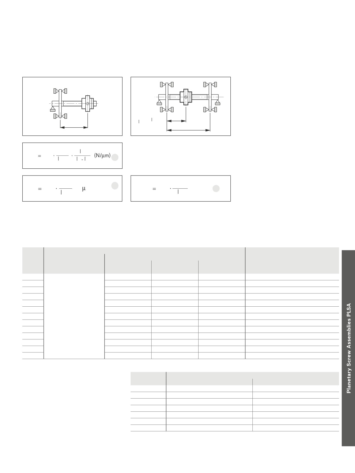
1 PLSA shaft is fixed at one end
2 PLSA shaft is fixed at both ends
RS/RS1 /RS2 = rigidity of the screw (N/µm)
d0
= nominal diameter
(mm)
lS
= distance between bearing
and bearing
(mm)
lS2
= distance between bearing
and nut
(mm)
lS2
S
lS1
S2 ≤
2
lS
The lowest screw rigidity occurs at the
(d0)2
S
center of the screw RS2min
R
165
S2
18
S2
S S2
( lS2 = lS/2) and thus equals:
2
(d0)
(d0)2
17
R
165
(N/ m)
RS2min
660
(N/µm)
19
S1
S1
S
Rigidity in the area of the nut unit Rnu
See the corresponding tables for rigidity values.
Preload and rigidity
d0 x P
Single nut FEM / ZEM
backlash
(preload class C2)
standard (mm)
Rnu (N/µm)
Tp0 (Nm)
Tp0 (Nm)
RS
N·m
(
µm
)
max.
min.
max.
20 x 5
0,03
400
0.29
0.66
66
25 x 5
460
0.42
0.92
103
25 x 10
290
0.42
0.92
103
30 x 5
620
0.57
1.24
149
30 x 10
420
0.57
1.24
149
39 x 5
750
0.88
1.92
251
39 x 10
500
0.88
1.92
251
48 x 5
1,080
1.24
2.72
380
48 x 10
760
1.24
2.72
380
60 x 10
1,030
1.79
3.94
594
60 x 20
700
1.79
3.94
594
75 x 10
1,400
2.61
5.17
928
75 x 20
1,000
2.61
5.17
928
d0 x P
Dynamic drag torque TRD approx. (Nm)
Frictional torque of the seals
Lip seal
Gap-type seal/cover plate wiper
Seal torque of the nuts
20 x 5
0.10
0
25 x 5/10
0.10
0
d0 x P = size
30 x 5/10
0.15
0
RS
= rigidity of the screw
39 x 5/10
0.25
0
Rnu = rigidity of the nut
48 x 5/10
0.35
0
TRD = dynamic drag torque of the 2 seals
60 x 10/20
0.50
0
Tp0 = dynamic drag torque without seals
75 x 10/20
0.70
0
T0
= overall dynamic drag torque
T0
= Tp0 + TRD
The values given for dynamic drag torque are proven practical indicators for the nut
preloading.
256
Screw Assemblies | Planetary Screw Assemblies PLSA
Installation
Installation
Delivery condition
Rexroth PLSAs are normally delivered prelubricated with an initial supply of grease. Relubri-
cation is possible, and cartridges and cans of this grease are available. If another lubricant is
used, you will need to check that it is compatible with the initial lubrication grease.
In special cases, a Ball Screw Assembly with only a preservative coating can be ordered
and supplied via the appropriate ordering code.
cc
Note
The selected lubricant must be in the nut before the machine is started.
cc
Note
In systems with a gap-type seal (Option 4), the user must additionally apply the stroke-de-
pendent amount of grease. (See section on Lubrication).
Cleaning
Various cleaning agents can be used to degrease and wash the assembly:
--
aqueous cleaning agents
-–
organic cleaning agents
cc
Note
Immediately after cleaning, thoroughly dry all parts and apply a preservative coating or
anti-corrosion oil.
In all cases, take care to observe the appropriate legal regulations (environmental protec-
tion, health and safety at work, etc.) as well as the specifications for the cleaning agent
(e.g. handling).
Storage
Planetary Screw Assemblies are high-quality systems that must be treated with due care. In
order to prevent damage and contamination, the elements should not be removed from the
protective wrapping until immediately before installation. Once they have been removed from
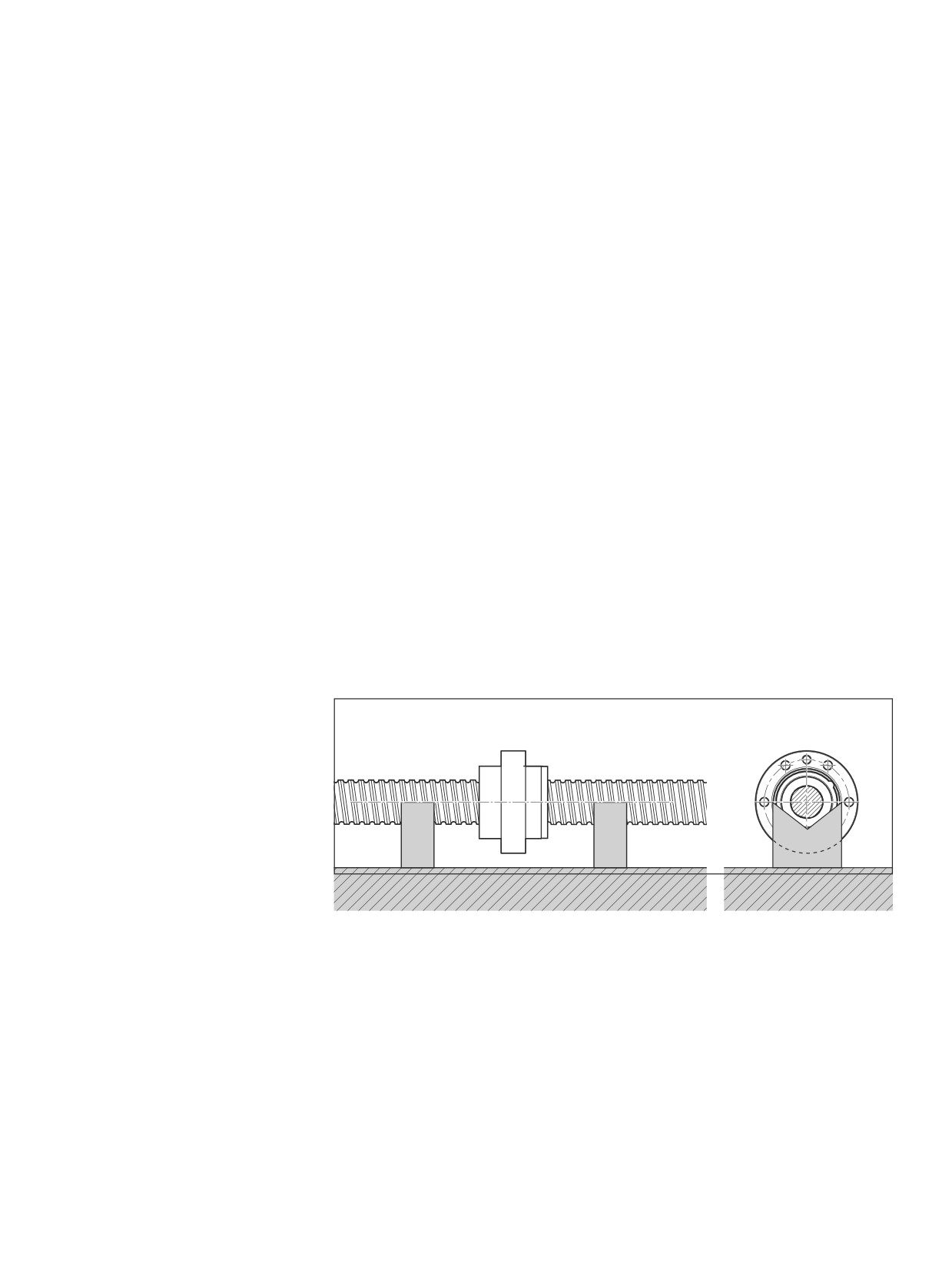
the packaging, they must be set down on V-shaped cradles.
Installation in the machine
It is not normally necessary to remove the preservative coating before installation.
--
If the Planetary Screw Assembly is contaminated, it must first be cleaned
(see “Cleaning”) and re-oiled
--
Push the nut unit into the mounting bore, taking care to avoid any impact force or
misalignment.
--
Tighten the mounting screws using a torque wrench if necessary. Maximum tightening
torque for the steel/steel material pairing (Rm ≥ 370 N/mm2), see table.
--
For the steel/aluminum and aluminum/aluminum material pairings (Rm ≥ 280 N/mm2), the
maximum tightening torques specified in the follow table apply.
When driving screws into aluminum, the length of thread engagement should be at least
1.5 times the screw diameter.
Planetary Screw Assemblies PLSA |
257
Installation
Steel/aluminum and aluminum/aluminum
Steel/steel material pairing
Tightening torques for fastening screws
material pairings
Screw
Tightening torque (Nm)
according to VDI 2230
Screw
Tightening torque (Nm)
diameter
Strength classes as per
where µG = µK = 0.125
diameter
Strength classes as per
(mm)
DIN ISO 898:
(mm)
DIN ISO 898:
8.8
10.9
12.9
8.8
10.9
12.9
M3
1.2
1.2
1.2
M3
1.3
1.8
2.1
M4
2.4
2.4
2.4
M4
2.7
3.8
4.6
Mounting screws
M5
4.8
4.8
4.8
M5
5.5
8.0
9.5
M6
8.5
8.5
8.5
M6
9.5
13.0
16.0
cc
Always make sure the screws
M8
20.0
20.0
20.0
M8
23.0
32.0
39.0
are secure where there are high screw
M10
41.0
41.0
41.0
M10
46.0
64.0
77.0
loads!
M12
70.0
70.0
70.0
M12
80.0
110.0
135.0
M14
110.0
110.0
110.0
M14
125.0
180.0
215.0
M16
175.0
175.0
175.0
M16
195.0
275.0
330.0
M18
250.0
250.0
250.0
M18
280.0
400.0
470.0
M20
345.0
345.0
345.0
M20
390.0
560.0
650.0
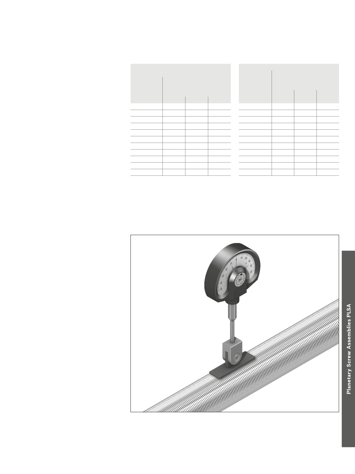
Alignment of the Planetary Screw Rexroth can provide a gauge with a self-aligning contact pad for easy alignment of the
Assembly in the machine
Planetary Screw Assembly.
Two pads of different lengths are available which can be used depending on the screw
lead:
--
material no. R3305 131 19: length 33 mm
-–
material no. R3305 131 21: length 50 mm
Dial gauge not supplied as standard with the Planetary Screw Assembly
258
Screw Assemblies | Planetary Screw Assemblies PLSA
Installation
Installation Tolerances
To ensure that a PLSA can actually achieve the calculated service life and performance,
its system-related requirements and limitations must be taken into account at the design
stage. Screw assemblies are not suitable for transferring radial forces and torques, such
as may be caused by misalignments during installation. The following sections illustrate the
most important principles for achieving designs that will be compatible with the screw drive
system and its requirements.
When using PLSAs, the specified installation tolerances must be observed when designing
and building the adjoining structures. The first basic principle is: The higher the PLSA’s
precision and preload, the more accurate the adjoining structures must be.
This applies in particular to applications in which the nut travels close up to the end
bearings since, in this area, the risk of distortive stresses and therefore of additional loads
is very high.
L
2 · d0
//
Y
A
2 · d
0
A
X
A
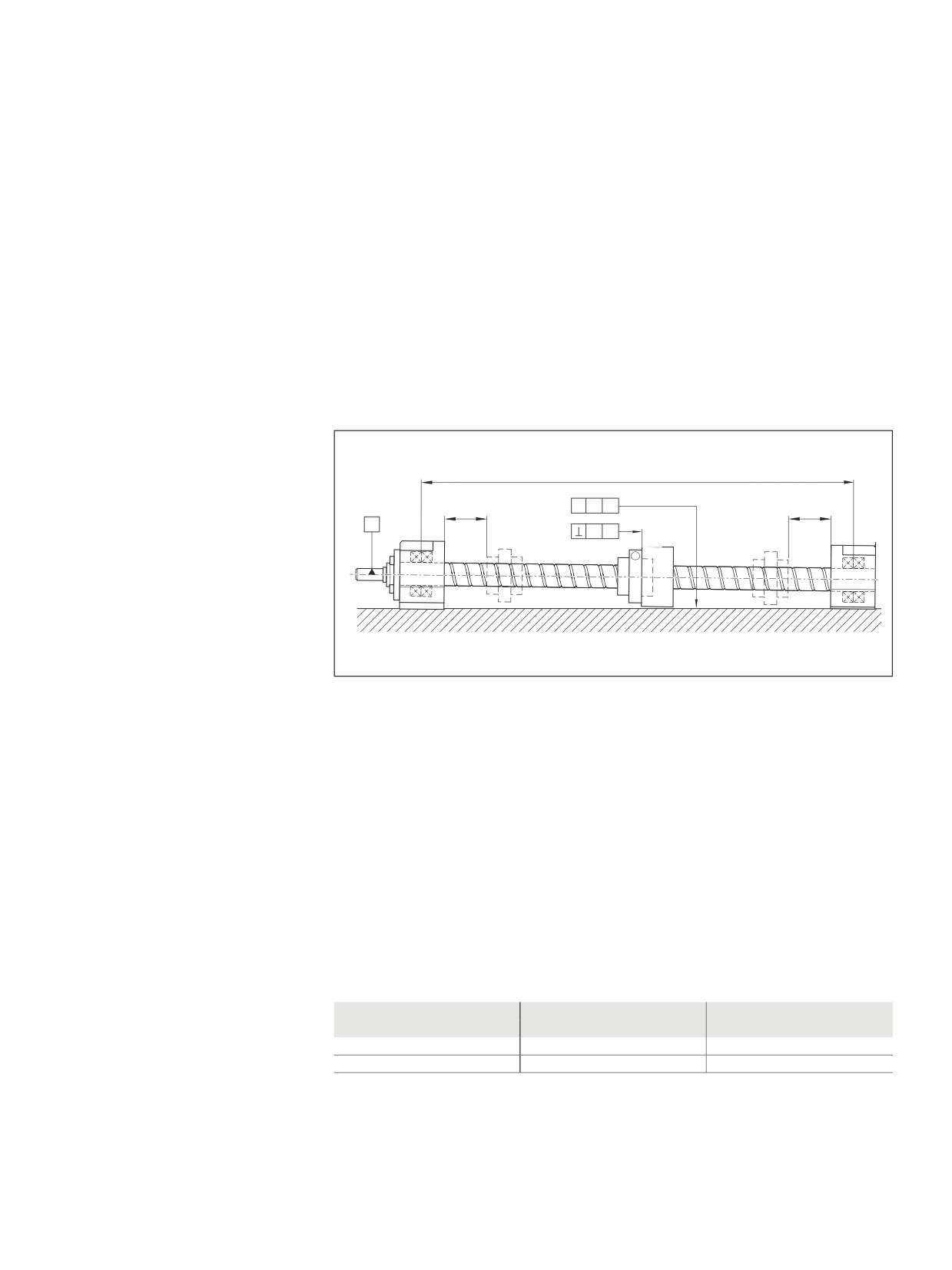
Parallelism offset and details of the rectangularity between the screw shaft axis and the
location face of the nut housing.
L
= distance between end bearings (mm)
d0
= nominal diameter of screw (mm)
X
= permissible deviation from rectangularity (mm)
The tolerance applies to a surface that must lie between two planes spaced at a
distance X from each other which are perpendicular to the reference axis A.
Y
= Permissible parallelism offset between the guide and the screw axis (mm)
The table shows the most important recommended tolerances for Planetary Screw Assem-
blies as a function of the preload. These tolerances include the rectangularity of the nut
housing (or adjoining structure) relative to the screw axis. The tolerances for parallelism
between the guide and the screw axis must also be complied with.
Any alignment errors can lead to premature breakdown of the Planetary Screw Assembly!
Option
X
Y
Preload
(mm)
(mm)
Backlash
0.02
0.02
Preload
0.01
0.01