Rexroth: Screw Assemblies. Catalog (R999001185/2018-10) - page 4
46
Screw Assemblies | Ball Screw Assemblies BASA
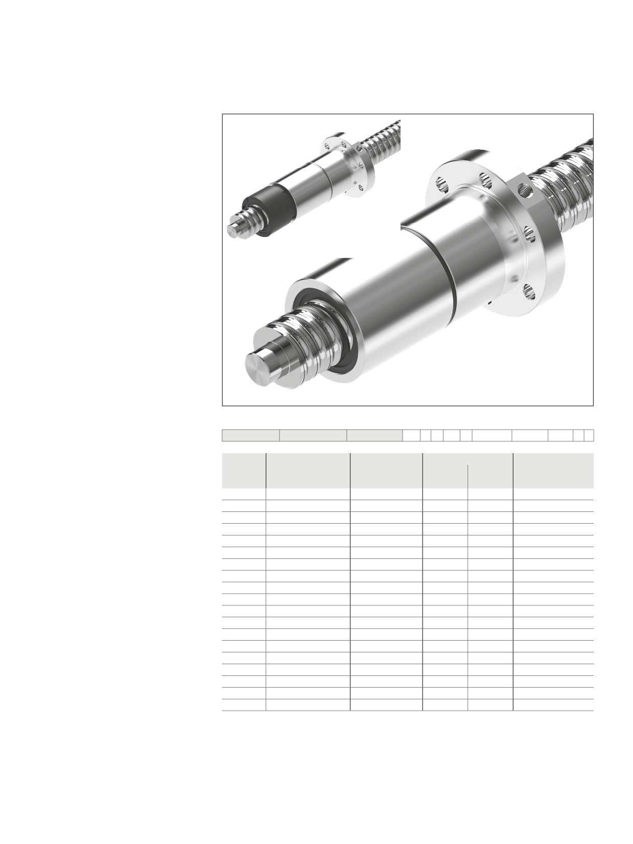
Nuts, standard series
Double nut with flange FDM-E-S
Rexroth connection dimensions
With seals,
preload class: C4, C5
Tolerance grades T32), T5, T7
Note: Supplied only as complete
Ball Screw Assembly.
cc
When setting up applications, do
not allow components to collide with the
front lube unit.
Ordering data:
d0
= nominal diameter
BASA
20 x 5R x 3
FDM-E-S - 4
00
1
5
T7
R
82Z120
41Z120
1250
0
1
P
= lead (R = right-hand)
DW = ball diameter
Category
Size
Part number
Load ratings3)
Linear speed1)
i
= number of ball track turns
dyn. C
stat. C0
vmax
d0 x P x Dw - i
(N)
(N)
(m/min)
C
16 x 5R x 3 - 4
R1502 010 23
14,800
16,100
30
C
20 x 5R x 3 - 4
R1502 110 33
17,200
21,500
30
C
25 x 5R x 3 - 4
R1502 210 33
19,100
27,200
30
C
25 x 10R x 3 - 4
R1502 240 33
18,800
27,000
60
C
32 x 5R x 3.5 - 4
R1502 310 33
25,900
40,000
23
C
32 x 10R x 3.969 - 5
R1502 340 33
38,000
58,300
47
C
40 x 5R x 3.5 - 5
R1502 410 33
34,900
64,100
19
C
40 x 10R x 6 - 4
R1502 440 33
60,000
86,400
38
C
40 x 10R x 6 - 6
R1502 440 34
86,500
132,200
38
C
40 x 20R x 6 - 3
R1502 470 33
45,500
62,800
75
C
50 x 5R x 3.5 - 5
R1502 510 33
38,400
81,300
15
C
50 x 10R x 6 - 4
R1502 540 33
66,500
109,000
30
C
50 x 10R x 6 - 6
R1502 540 34
95,600
166,500
30
C
50 x 20R x 6.5 - 5
R1502 570 34
90,800
149,700
60
C
63 x 10R x 6 - 4
R1502 640 33
74,200
140,500
24
C
63 x 10R x 6 - 6
R1502 640 34
106,600
214,300
24
C
63 x 20R x 6.5 - 5
R1502 670 34
100,700
190,300
48
C
80 x 10R x 6.5 - 6
R1502 740 34
130,100
291,700
19
C
80 x 20R x 12.7 - 6
R1502 770 04
315,200
534,200
30
1) See “Characteristic speed d0 · n” on page 141 and “Critical speed ncr” on page 176
2) Tolerance grade T3 for sizes shown in table page 12
3) The load ratings are valid for tolerance grade T3 and T5 only.
For other tolerance grades, please take into account the correction factor fac on page 141.
47
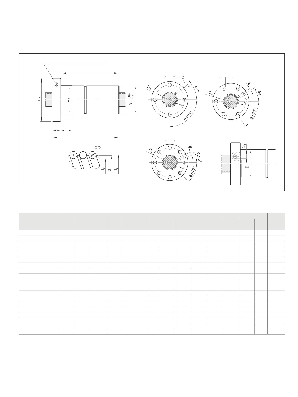
Nuts, standard series
Lube port4) at flange center
BB3
BB4
L10
D7
D7
L3
L4
BB5
L
Nut rework: Axial lube port5)
D7
4) Lube port machining: flat surface L3 ≤ 15 mm, countersink L3 > 15 mm
5) The axial lube port Sx is always located on the pitch circle D6 of the nut unit.
Size
(mm)
Mass
d1
d2
D1
D5
Hole pattern
D6
D7
L
L3
L4
L10
S4)
Sx
m
d0 x P x Dw - i
g6
(kg)
16 x 5R x 3 - 4
15.0
12.9
28
53
BB3
40
6.6
72
12
10
60
M6
4
0.33
20 x 5R x 3 - 4
19.0
16.9
33
58
BB4
45
6.6
82
12
10
70
M6
4
0.45
25 x 5R x 3 - 4
24.0
21.9
38
63
BB4
50
6.6
82
12
10
70
M6
4
0.53
25 x 10R x 3 - 4
24.0
21.9
38
63
BB4
50
6.6
120
12
16
108
M6
4
0.70
32 x 5R x 3.5 - 4
31.0
28.4
48
73
BB4
60
6.6
88
13
10
75
M6
4
0.84
32 x 10R x 3.969 - 5
31.0
27.9
48
73
BB4
60
6.6
146
13
16
133
M6
4
1.22
40 x 5R x 3.5 - 5
39.0
36.4
56
80
BB4
68
6.6
100
15
10
85
M8x1
5
1.13
40 x 10R x 6 - 4
38.0
33.8
63
95
BB4
78
9.0
140
15
16
125
M8x1
5
2.25
40 x 10R x 6 - 6
38.0
33.8
63
95
BB4
78
9.0
180
15
16
165
M8x1
5
2.83
40 x 20R x 6 - 3
38.0
33.8
63
95
BB4
78
9.0
175
15
25
160
M8x1
5
2.66
50 x 5R x 3.5 - 5
49.0
46.4
68
98
BB4
82
9.0
100
15
10
85
M8x1
5
1.60
50 x 10R x 6 - 4
48.0
43.8
72
110
BB4
90
11.0
140
18
16
122
M8x1
5
2.74
50 x 10R x 6 - 6
48.0
43.8
72
110
BB4
90
11.0
180
18
16
162
M8x1
5
3.39
50 x 20R x 6.5 - 5
48.0
43.4
85
125
BB4
105
11.0
255
22
25
233
M8x1
5
6.71
63 x 10R x 6 - 4
61.0
56.8
85
125
BB4
105
11.0
140
22
16
118
M8x1
5
3.53
63 x 10R x 6 - 6
61.0
56.8
85
125
BB4
105
11.0
180
22
16
158
M8x1
5
4.32
63 x 20R x 6.5 - 5
61.0
56.3
95
140
BB4
118
14.0
255
22
25
233
M8x1
5
8.65
80 x 10R x 6.5 - 6
78.0
73.3
105
150
BB4
125
14.0
190
22
16
168
M8x1
5
6.35
80 x 20R x 12.7 - 6
76.0
67.0
125
180
BB5
152
18.0
340
25
25
315
M8x1
5
20.20
48
Screw Assemblies | Ball Screw Assemblies BASA
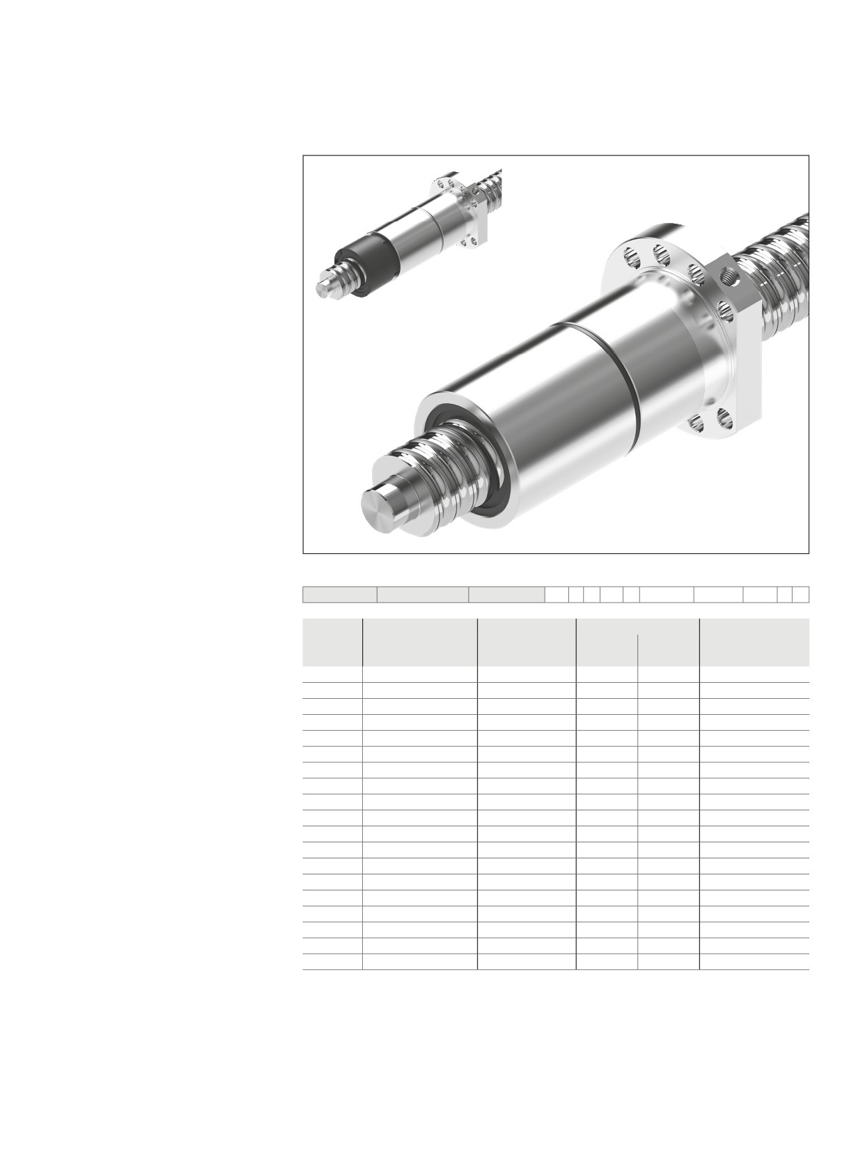
Nuts, standard series
Double nut with flange FDM-E-C
Mounting dimensions similar to
DIN 69051, Part 5
Flange type C
(flange type B available. See ordering
code p. 22)
With seals, preload class: C4, C5
Tolerance grades T32), T5, T7
Note: Supplied only as complete
Ball Screw Assembly.
cc
When setting up applications, do
not allow components to collide with the
front lube unit.
Ordering data:
d0
= nominal diameter
P
= lead (R = right-hand)
BASA
20 x 5R x 3
FDM-E-S - 4
00
1
5
T7
R
82Z120
41Z120
1250
0
1
DW = ball diameter
Category
Size
Part number
Load ratings3)
Linear speed1)
i
= number of ball track turns
dyn. C
stat. C0
vmax
d0 x P x Dw - i
(N)
(N)
(m/min)
C
16 x 5R x 3 - 4
R1502 010 55
14,800
16,100
30
C
20 x 5R x 3 - 4
R1502 110 75
17,200
21,500
30
C
25 x 5R x 3 - 4
R1502 210 75
19,100
27,200
30
C
25 x 10R x 3 - 4
R1502 240 75
18,800
27,000
60
C
32 x 5R x 3.5 - 4
R1502 310 75
25,900
40,000
23
C
32 x 10R x 3.969 - 5
R1502 340 76
38,000
58,300
47
C
40 x 5R x 3.5 - 5
R1502 410 76
34,900
64,100
19
C
40 x 10R x 6 - 4
R1502 440 75
60,000
86,400
38
C
40 x 10R x 6 - 6
R1502 440 76
86,500
132,200
38
C
40 x 20R x 6 - 3
R1502 470 75
45,500
62,800
75
C
50 x 5R x 3.5 - 5
R1502 510 76
38,400
81,300
15
C
50 x 10R x 6 - 4
R1502 540 75
66,500
109,000
30
C
50 x 10R x 6 - 6
R1502 540 76
95,600
166,500
30
C
50 x 20R x 6.5 - 5
R1502 570 76
90,800
149,700
60
C
63 x 10R x 6 - 4
R1502 640 75
74,200
140,500
24
C
63 x 10R x 6 - 6
R1502 640 76
106,600
214,300
24
C
63 x 20R x 6.5 - 5
R1502 670 76
100,700
190,300
48
C
80 x 10R x 6.5 - 6
R1502 740 76
130,100
291,700
19
C
80 x 20R x 12.7 - 6
R1502 770 46
315,200
534,200
30
1) See “Characteristic speed d0 · n” on page 141 and “Critical speed ncr” on page 176
2) Tolerance grade T3 for sizes shown in table page 12
3) The load ratings are valid for tolerance grade T3 and T5 only.
For other tolerance grades, please take into account the correction factor fac on page 141.
49
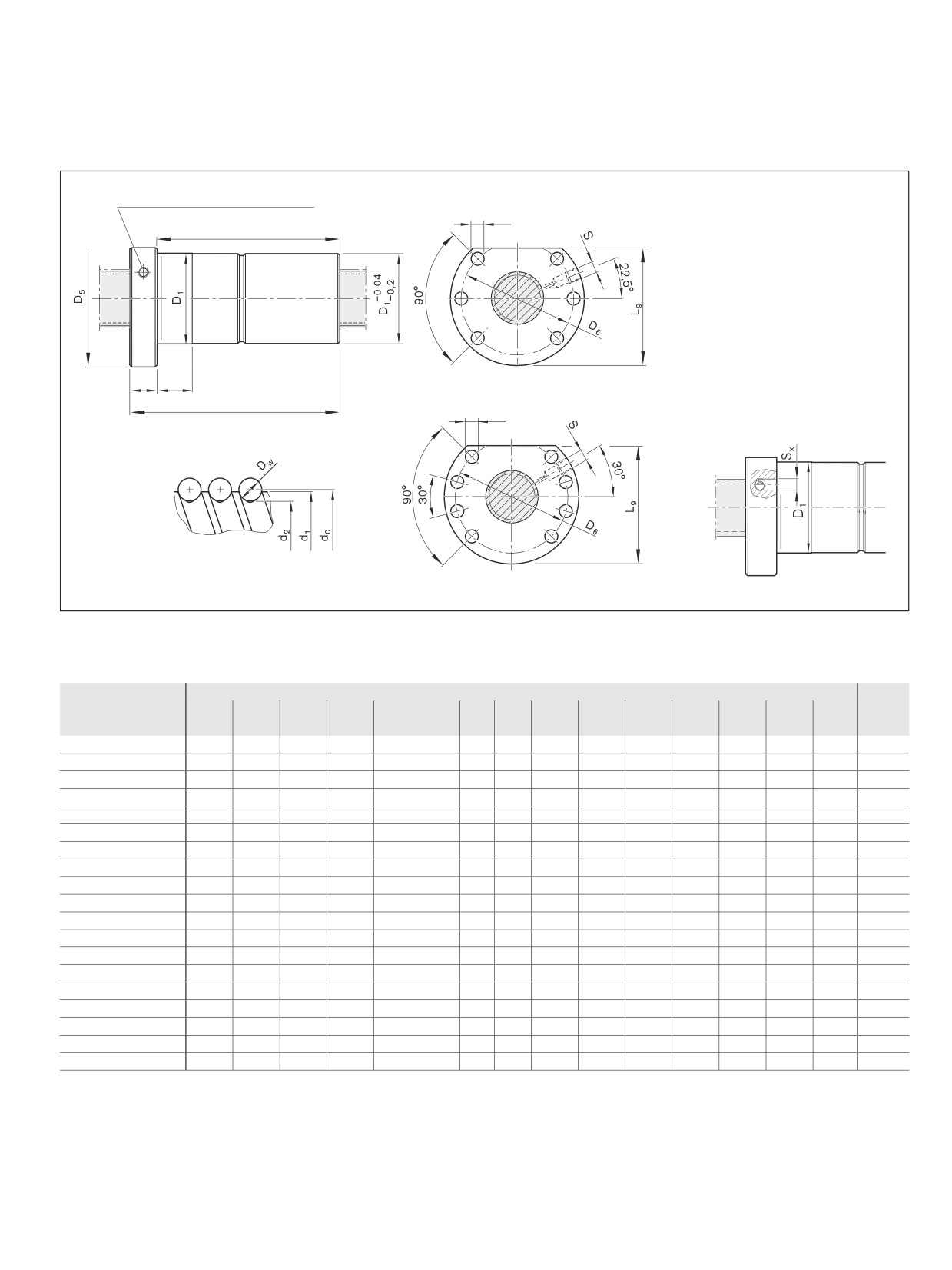
Nuts, standard series
Lube port4) at flange center
BB2
d0 ≤ 32
D7
L10
L3
L4
BB1
d0 ≥ 40
L
D7
Nut rework: Axial lube port5)
4) Lube port machining: flat surface L3 ≤ 15 mm, countersink L3 > 15 mm
5) The axial lube port Sx is always located on the pitch circle D6 of the nut unit.
Size
(mm)
Mass
d1
d2
D1
D5
Hole pattern
D6
D7
L
L3
L4
L96)
L10
S4)
Sx
m
d0 x P x Dw - i
g6
(kg)
16 x 5R x 3 - 4
15.0
12.9
28
48
BB2
38
5.5
72
12
10
44.0
60
M6
4
0.29
20 x 5R x 3 - 4
19.0
16.9
36
58
BB2
47
6.6
82
12
10
51.0
70
M6
4
0.53
25 x 5R x 3 - 4
24.0
21.9
40
62
BB2
51
6.6
82
12
10
55.0
70
M6
4
0.57
25 x 10R x 3 - 4
24.0
21.9
40
62
BB2
51
6.6
120
12
16
55.0
108
M6
4
0.77
32 x 5R x 3.5 - 4
31.0
28.4
50
80
BB2
65
9.0
88
13
10
71.0
75
M6
4
0.96
32 x 10R x 3.969 - 5
31.0
27.9
50
80
BB2
65
9.0
146
13
16
71.0
133
M6
4
1.34
40 x 5R x 3.5 - 5
39.0
36.4
63
93
BB1
78
9.0
100
15
10
81.5
85
M8x1
5
1.68
40 x 10R x 6 - 4
38.0
33.8
63
93
BB1
78
9.0
140
15
16
81.5
125
M8x1
5
2.15
40 x 10R x 6 - 6
38.0
33.8
63
93
BB1
78
9.0
180
15
16
81.5
165
M8x1
5
2.73
40 x 20R x 6 - 3
38.0
33.8
63
93
BB1
78
9.0
175
15
25
81.5
160
M8x1
5
2.56
50 x 5R x 3.5 - 5
49.0
46.4
75
110
BB1
93
11.0
100
15
10
97.5
85
M8x1
5
2.25
50 x 10R x 6 - 4
48.0
43.8
75
110
BB1
93
11.0
140
18
16
97.5
122
M8x1
5
2.97
50 x 10R x 6 - 6
48.0
43.8
75
110
BB1
93
11.0
180
18
16
97.5
162
M8x1
5
3.73
50 x 20R x 6.5 - 5
48.0
43.3
75
110
BB1
93
11.0
255
18
25
97.5
237
M8x1
5
4.93
63 x 10R x 6 - 4
61.0
56.8
90
125
BB1
108
11.0
140
22
16
110.0
118
M8x1
5
4.00
63 x 10R x 6 - 6
61.0
56.8
90
125
BB1
108
11.0
180
22
16
110.0
158
M8x1
5
4.45
63 x 20R x 6.5 - 5
61.0
56.3
95
135
BB1
115
13.5
255
22
25
117.5
233
M8x1
5
8.21
80 x 10R x 6.5 - 6
78.0
73.3
105
145
BB1
125
13.5
190
22
16
127.5
168
M8x1
5
5.93
80 x 20R x 12.7 - 6
76.0
67.0
125
165
BB1
145
13.5
340
25
25
147.5
315
M8x1
5
19.40
6) Flange type B (two flat surfaces) option available!
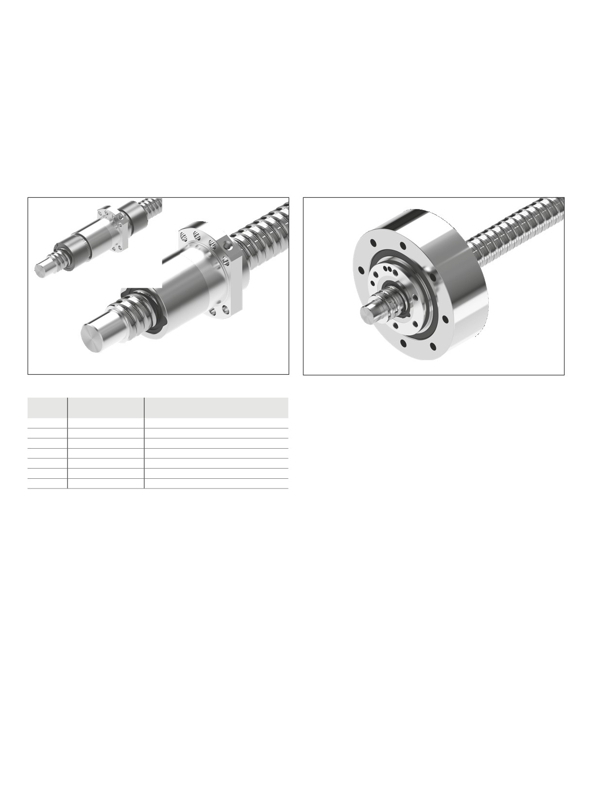
50
Screw Assemblies | Ball Screw Assemblies BASA
Nuts, high-performance series
Nuts, high-performance series
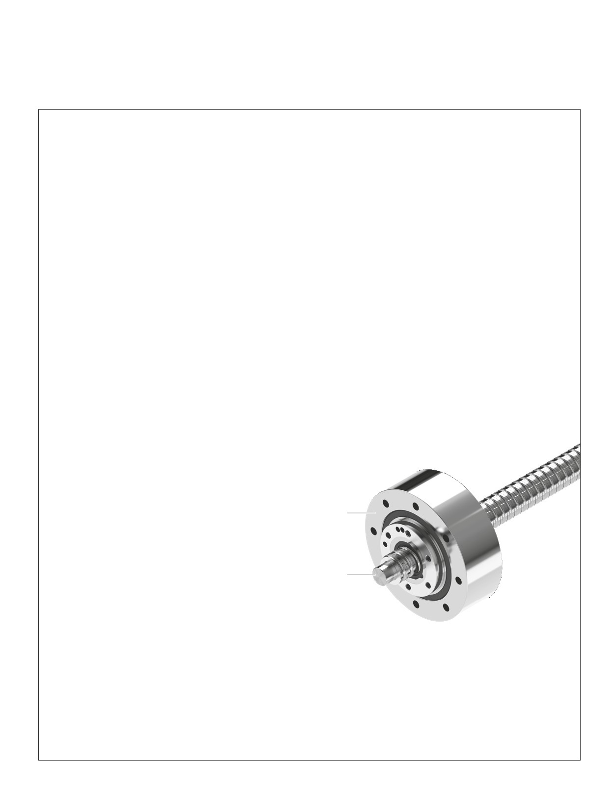
High-performance series
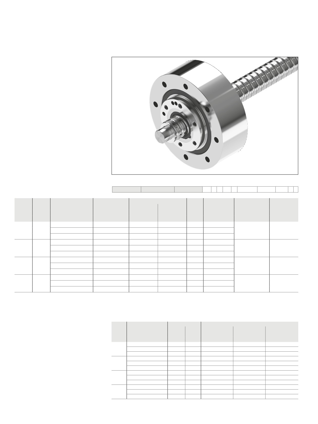
HP series Ball Screw Assemblies are available with
nominal diameters of 20 - 63 mm, and leads of 10 - 40 mm.
The HP nut type is a single nut with flange which is available with
a driven screw or as a driven nut.
FED-E-B
FAR-
Preload classes
Option
Preload class
Definition
0
C0
Standard backlash
1
C00
Reduced backlash
2
C3
High preload (single nut)
3
C1
Moderate preload (single nut)
4
C4
High preload (double nut)
5
C5
Average preload (double nut)
6
C2
Average preload (single nut)
See nut versions for allocation of the preload classes
51
Nuts, high-performance series
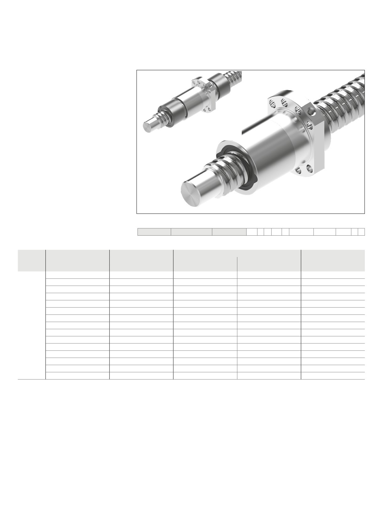
Driven single nut with flange FAR-B-S
Fundamental advantages of systems with driven nuts
Moment of inertia
In the case of long screws, the screw does not have to be rotated in the acceleration phase, only the nut.
The mass moment of inertia of the screw is not therefore critical. The moment of inertia of the nut is comparatively low and it is no longer
dependent on the required stroke.
Dynamics
The intricate end bearing designs required for high dynamics, for example, fixed bearing on both ends with angular-contact ball bearings,
are no longer necessary.
Screw extenders
Since the screw is stationary, relatively effort is needed to stretch the screw
--
Increase in permissible axial loading (buckling load); not limited by end bearings
-–
Compensation of temperature influences
-–
Increase in overall rigidity
Design and manufacturing tolerances
The use of nuts with a high level of axial and radial runout precision minimizes the induced screw vibration. All functional components are
supplied from a single source. In-house designs are no longer needed.
Liquid cooling
Improved cooling can easily be provided by using a hollow-bored screw:
cooling of the stationary screw can be provided with comparatively little effort. Controlled cooling virtually eliminates changes in length
due to temperature fluctuations.
User benefits
--
Economic efficiency provided by complete unit
-–
Adjustment to various speeds and loads is possible using the
screw lead and the speed reducing belt
--
Small installation space thanks to its compact construction
2
-–
Integral functionality and little installation work for the customer
-–
Low system costs
-–
High positioning accuracy
-–
For particularly demanding positioning tasks, it can be com-
bined with the direct position measuring system that is inte-
1
grated in the guide rail
1 Ball Screw Assemblies (BASA)
screw
2 Driven nut FAR
52
Screw Assemblies | Ball Screw Assemblies BASA
Nuts, high-performance series
Single nut with flange FED-E-B
Mounting dimensions similar to
DIN 69051, Part 5 flange type B
Nut for significantly increasing the dynamic
and static load capacity
With standard seals
Preload class: C0, C00, C1, C2
Tolerance grade T31), T5, T7, T9
cc
When setting up applications, do
not allow components to collide with the
front lube unit.
Ordering data:
BASA
40x20R x 6
FED-E-B - 8
00
1
2
T5
R
82Z300
41K300
1250
0
1
Category
Size
Part number
Load ratings3)
Linear speed2)
dyn. C
stat. C0
vmax
d0 x P x DW - i
(N)
(N)
(m/min)
B
16 x 16 R x 3 - 6
R1512 060 32
17 800
24 200
96
20 x 20 R x 3.5 - 6
R1512 170 32
25 700
38 100
120
25 x 25 R x 3.5 - 6
R1512 280 32
28 500
47 100
150
32 x 20 R x 3.969 - 6
R1512 370 32
38 300
67 300
94
32 x 32 R x 3.969 - 6
R1512 390 32
37 900
68 000
150
40 x 20 R x 6 - 8
R1512 470 32
95 500
171 100
75
40 x 25 R x 6 - 8
R1512 480 32
91 400
171 700
93
40 x 30 R x 6 - 8
R1512 4A0 32
90 400
170 300
112
40 x 40 R x 6 - 6
R1512 490 32
71 500
124 500
150
50 x 20 R x 6.5 - 8
R1512 570 32
116 500
240 000
60
50 x 25 R x 6.5 - 6
R1512 580 32
92 600
175 100
75
50 x 30 R x 6.5 - 6
R1512 5A0 32
114 500
237 700
90
50 x 40 R x 6.5 - 6
R1512 590 32
89 300
171 500
120
63 x 20 R x 6.5 - 8
R1512 670 32
130 800
292 000
48
63 x 40 R x 6.5 - 6
R1512 690 32
100 000
230 600
95
1) Tolerance grade T3 for sizes shown in table page 12
2) See “Characteristic speed d0 · n” on page 141 and “Critical speed ncr” on page 176
3) The load ratings are valid for tolerance grade T3 and T5 only.
For other tolerance grades, please take into account the correction factor fac on page 141.
d0
= nominal diameter
P
= lead (R = right-hand)
DW = ball diameter
i
= number of ball track turns
53
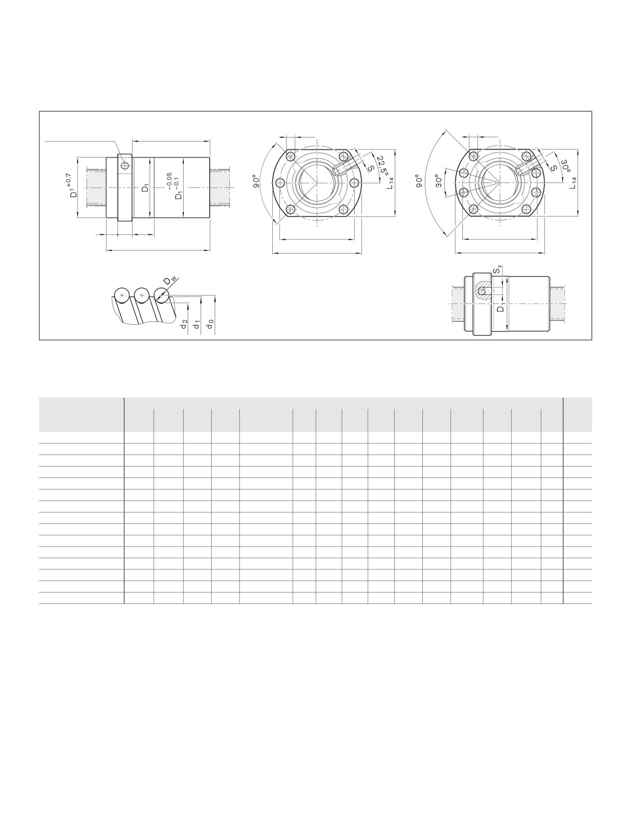
Nuts, high-performance series
BB2
d0
≤ 32
BB1
d0
≥ 40
D
7
D
7
Lube port4) at
L10
flange center
L5
L3
L4
D
D6
6
L
D
D
5
5
Nut rework: Axial lube port5)
4)
Lube port machining: flat surface L3 ≤ 15 mm, countersink L3 > 15 mm
5)
The axial lube port Sx is always located on the pitch circle D6 of the nut unit.
Size
(mm)
Mass
d1
d2
D1
D5
Hole pattern
D6
D7
L
L3
L4
L5
L10
L14
S4)
Sx
m
d0 x P x DW - i
g6
(kg)
16 x 16 R x 3 - 6
15.0
12.9
28
48
BB2
38
5.5
61
12
20
6.0
43.0
40
M6
4
0.27
20 x 20 R x 3.5 - 6
19.0
16.7
36
58
BB2
47
6.6
77
12
25
8.0
57.0
44
M6
4
0.48
25 x 25 R x 3.5 - 6
24.0
21.4
40
62
BB2
51
6.6
95
12
30
9.0
74.0
48
M6
4
0.63
32 x 20 R x 3.969 - 6
31.0
27.9
50
80
BB2
65
9.0
84
13
25
11.0
60.0
62
M6
4
0.91
32 x 32 R x 3.969 - 6
31.0
27.9
50
80
BB2
65
9.0
120
13
40
12.0
95.0
62
M6
4
1.25
40 x 20 R x 6 - 8
38.0
33.8
63
93
BB1
78
9.0
108
15
25
13.0
80.0
70
M8x1
5
1.85
40 x 25 R x 6 - 8
38.0
33.8
63
93
BB1
78
9.0
127
15
30
11.5
100.5
70
M8x1
5
1.88
40 x 30 R x 6 - 8
38.0
33.8
63
93
BB1
78
9.0
145
15
35
11.5
118.5
70
M8x1
5
2.13
40 x 40 R x 6 - 6
38.0
33.8
63
93
BB1
78
9.0
142
15
45
11.5
115.5
70
M8x1
5
2.35
50 x 20 R x 6.5 - 8
48.0
43.3
75
110
BB1
93
11.0
112
18
25
13.0
81.0
85
M8x1
5
2.50
50 x 25 R x 6.5 - 6
48.0
43.3
75
110
BB1
93
11.0
107
18
25
13.5
75.5
85
M8x1
5
2.45
50 x 30 R x 6.5 - 6
48.0
43.3
75
110
BB1
93
11.0
151
18
35
15.0
118.0
85
M8x1
5
3.04
50 x 40 R x 6.5 - 6
48.0
43.3
75
110
BB1
93
11.0
149
18
45
15.0
116.0
85
M8x1
5
3.40
63 x 20 R x 6.5 - 8
61.0
56.3
95
135
BB1
115
13.5
112
22
25
11.0
79.0
100
M8x1
5
3.90
63 x 40 R x 6.5 - 6
61.0
56.3
95
135
BB1
115
13.5
149
22
45
12.0
115.0
100
M8x1
5
5.05
54
Screw Assemblies | Ball Screw Assemblies BASA
Nuts, high-performance series
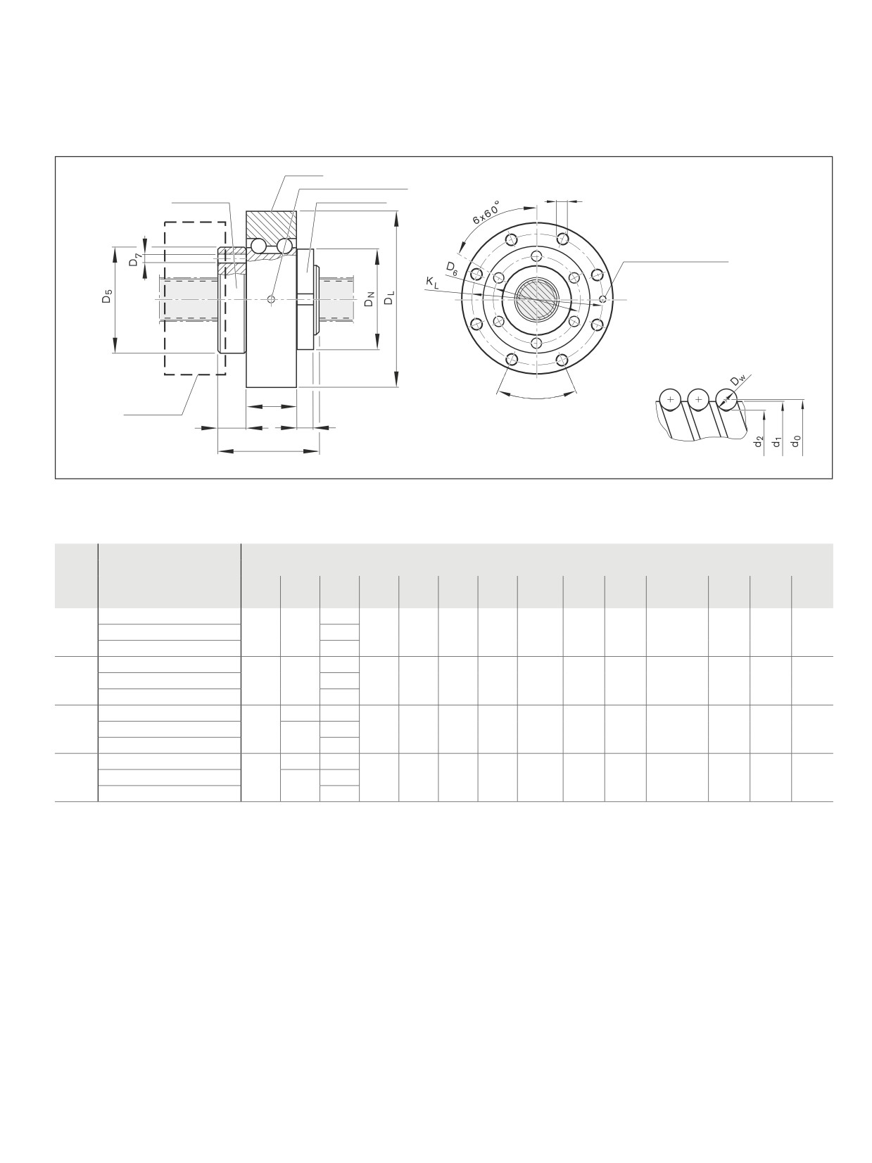
Driven single nut with flange FAR-B-S
Rexroth connection dimensions
With seals,
preload class: C1, C2, C3
Tolerance grade T32), T5, T7
The unit consists of:
nut, angular-contact thrust ball bearing and
slotted nut NMZ
When in standstill, it can be relubricated
with NLGI Class 2 grease via the stationary
lube port of the bearing outer race
Note: Supplied only as complete
Ball Screw Assembly.
d0
= nominal diameter
P
= lead (R = right-hand)
DW = ball diameter
i
= number of ball track turns
Ordering data:
BASA
40x20R x 6
FAR-B-S - 3
00
1
6
T5
R
51K300
51K300
1250
0
1
Cat-
FAR
Size
Part number
Load ratings1) 4)
Mass
Mass moment
Frictional torque
Max. speed 3)
egory
size
Module
of inertia
Bearing
dyn. C
stat. C0
mFAR
JrotFAR
MRL
nG
d0 x P x Dw - i
(N)
(N)
(kg)
(kg · m2 · 10-4)
(Nm)
(rpm)
C
32
32 x 10R x 3.969 - 5
R2532 301 01
38,000
58,300
5.8
22.5
1.0
3 000
32 x 20R x 3.969 - 3
R2532 301 11
23,600
33,700
5.9
22.9
32 x 32R x 3.969 - 3
R2532 301 21
23,400
34,000
6.3
25.1
C
40
40 x 10R x 6 - 5
R2532 401 01
73,400
109,300
7.3
42.7
1.2
2 800
40 x 20R x 6 - 3
R2532 401 31
45,500
62,800
7.5
43.9
40 x 40R x 6 - 3
R2532 401 41
44,400
62,300
8.4
50.7
C
50
50 x 10R x 6 - 6
R2532 501 01
95,600
166,500
8.3
67.6
1.4
2 700
50 x 20R x 6.5 - 5
R2532 501 31
90,800
149,700
9.1
76.0
50 x 40R x 6.5 - 3
R2532 501 41
55,800
85,900
9.5
79.8
C
63
63 x 10R x 6 - 6
R2532 601 01
106,600
214,300
12.8
139.0
2.3
2 300
63 x 20R x 6.5 - 5
R2532 601 11
100,700
190,300
13.5
156.4
63 x 40R x 6.5 - 3
R2532 601 21
64,100
114,100
13.9
161.6
1) Load ratings calculated according to DIN ISO 3408-5
2) Tolerance grade T3 for sizes shown in table page 12
3) Limited by the max. speed of the bearing. Bearing pre-tensioned without external operating load. Duty cycle 25%; max. steady-state temp. +50 °C
4) The load ratings are valid for tolerance grade T3 and T5 only.
For other tolerance grades, please take into account the correction factor fac on page 141.
FAR
Size
Rigidity
Overall rigidity of the nut unit (N/µm)
FAR rigidity levels
size
Screw
Bearing
Preload class C1
Preload class C2
Preload class C3
RS
RaL
RG
RG
RG
d0 x P x Dw - i
(Nm/µm)
(N/µm)
32
32 x 10R x 3.969 - 5
141
860
320
350
380
32 x 20R x 3.969 - 3
141
860
220
250
280
32 x 32R x 3.969 - 3
141
860
220
240
270
40
40 x 10R x 6 - 5
211
950
390
420
450
40 x 20R x 6 - 3
211
950
270
300
330
40 x 40R x 6 - 3
211
950
270
290
330
50
50 x 10R x 6 - 6
345
1,050
490
520
560
50 x 20R x 6.5 - 5
340
1,050
450
480
530
50 x 40R x 6.5 - 3
340
1,050
320
350
390
63
63 x 10R x 6 - 6
569
1,150
560
600
640
63 x 20R x 6.5 - 5
563
1,150
520
560
610
63 x 40R x 6.5 - 3
563
1,150
390
420
460
55
Nuts, high-performance series
Bearing
SL lube port
dL
BASA nut
Slotted nut NMZ
SL
Lube port
8 x 45°
BL
Belt pulley
L3
BN
LFAR
FAR
Size
Dimensions (mm)
size
d1
d2
LFAR
D5
D6
D7
L3
DL
BL
KL
dL
SL5)
DN
BN
d0 x P x Dw - i
h6
-0.018
+0.3/-0.1
32
32 x 10R x 3.969 - 5
31
27.9
77
80
65
M8
11
145
49
120
8.8
M6
75
16
32 x 20R x 3.969 - 3
84
32 x 32R x 3.969 - 3
120
40
40 x 10R x 6 - 5
38
33.8
80
93
80
M8
12
155
49
130
8.8
M6
92
18
40 x 20R x 6 - 3
88
40 x 40R x 6 - 3
142
50
50 x 10R x 6 - 6
48
43.8
90
105
90
M8
13
165
49
140
8.8
M6
105
18
50 x 20R x 6.5 - 5
43.3
132
50 x 40R x 6.5 - 3
149
63
63 x 10R x 6 - 6
61
56.8
100
130
110
M10
20
190
60
165
11.0
M6
120
20
63 x 20R x 6.5 - 5
56.3
132
63 x 40R x 6.5 - 3
149
5) Condition on delivery: lube ports SL sealed by setscrews (M6).
The desired lube port can be opened by removing the set screw.
56
Screw Assemblies | Ball Screw Assemblies BASA
Screws
Precision screw
Please state length in the
Ltot
“Inquiry/Order Form”
Ltot =
overall length

57
Screws
Size
Part number
(mm)
Moment of inertia
Maximum length (mm)
Mass
Tolerance grade
Js
Standard
on request
d0 x P x DW
T5
T7
T9
d1
d2
(kg · cm2/m)
(kg/m)
61) x 1R x 0.8
-
-
-
6.0
5.3
0.02
-
-
0.19
61) x 2R x 0.8
-
-
-
6.0
5.3
0.02
-
-
0.19
81) x 1R x 0.8
-
-
-
8.0
7.3
0.04
-
-
0.36
81) x 2R x 1.2
-
-
-
8.0
7.0
0.04
-
-
0.36
8 x 2.5R x 1.588
R1531 235 00
R1531 237 00
R1531 239 00
7.5
6.3
0.04
1 500
2 500
0.30
8 x 5R x 1.588
R1531 265 00
R1531 267 00
R1531 269 00
7.5
6.3
0.04
1 500
2 500
0.30
121) x 2R x 1.2
-
-
-
11.7
10.7
0.13
-
-
0.79
12 x 5R x 2
R1531 465 10
R1531 467 10
R1531 469 10
11.4
9.9
0.11
1 500
2 500
0.75
12 x 10R x 2
R1531 495 00
R1531 497 00
R1531 499 00
11.4
9.9
0.11
0.74
16 x 5L x 3
R1551 015 00
R1551 017 00
R1551 019 00
15.0
12.9
0.31
1 500
3 500
1.24
16 x 5R x 3
R1511 015 00
R1511 017 00
R1511 019 00
15.0
12.9
0.31
1.24
16 x 10R x 3
R1511 045 00
R1511 047 00
R1511 049 00
15.0
12.9
0.31
1.23
16 x 16R x 3
R1511 065 10
R1511 067 10
R1511 069 10
15.0
12.9
0.34
1.29
20 x 5R x 3
R1511 115 00
R1511 117 00
R1511 119 00
19.0
16.9
0.84
1 500
3 500
2.03
20 x 5L x 3
R1551 115 00
R1551 117 00
R1551 119 00
19.0
16.9
0.84
2.03
20 x 10R x 3
R1511 145 00
R1511 147 00
R1511 149 00
19.0
16.9
0.84
2.03
20 x 20R x 3.5
R1511 175 10
R1511 177 10
R1511 179 10
19.0
16.7
0.81
1.99
201) x 40R x 3.5
-
-
-
19.0
16.4
0.86
-
-
2.06
25 x 5R x 3
R1511 215 00
R1511 217 00
R1511 219 00
24.0
21.9
2.22
2 500
5 500
3.31
25 x 5L x 3
R1551 215 00
R1551 217 00
R1551 219 00
24.0
21.9
2.22
3.31
25 x 10R x 3
R1511 245 00
R1511 247 00
R1511 249 00
24.0
21.9
2.39
3.43
25 x 25R x 3.5
R1511 285 10
R1511 287 10
R1511 289 10
24.0
21.4
2.15
3.25
32 x 5R x 3.5
R1511 315 00
R1511 317 00
R1511 319 00
31.0
28.4
6.05
2 500
5 500
5.45
32 x 5L x 3.5
R1551 315 00
R1551 317 00
R1551 319 00
31.0
28.4
6.05
5.45
32 x 10R x 3.969
R1511 345 10
R1511 347 10
R1511 349 10
31.0
27.9
6.40
5.60
32 x 20R x 3.969
R1511 375 10
R1511 377 10
R1511 379 10
31.0
27.9
6.39
5.60
32 x 32R x 3.969
R1511 395 10
R1511 397 10
R1511 399 10
31.0
27.9
6.17
5.50
321) x 64R x 3.969
-
-
-
31.0
27.9
6.04
-
-
5.44
40 x 5R x 3.5
R1511 415 00
R1511 417 00
R1511 419 00
39.0
36.4
15.64
4 500
5 500
8.78
40 x 5L x 3.5
R1551 415 00
R1551 417 00
R1551 419 00
39.0
36.4
15.64
8.78
40 x 10R x 6
R1511 445 00
R1511 447 00
R1511 449 00
38.0
33.8
13.55
7 500
8.15
40 x 10L x 6
R1551 445 00
R1551 447 00
R1551 449 00
38.0
33.8
13.55
8.15
40 x 12R x 6
R1511 455 00
R1511 457 00
R1511 459 00
38.0
33.8
13.97
5 000
8.27
40 x 16R x 6
R1511 465 00
R1511 467 00
R1511 469 00
38.0
33.8
12.90
7.95
40 x 20R x 6
R1511 475 00
R1511 477 00
R1511 479 00
38.0
33.8
13.52
7 500
8.14
40 x 25R x 6
R1511 485 00
R1511 487 00
R1511 489 00
38.0
33.8
13.51
5 000
8.67
40 x 30R x 6
R1511 4A5 00
R1511 4A7 00
R1511 4A9 00
38.0
33.8
13.71
8.67
40 x 40R x 6
R1511 495 10
R1511 497 10
R1511 499 10
38.0
33.8
13.42
7 500
8.11
50 x 5R x 3.5
R1511 515 00
R1511 517 00
R1511 519 00
49.0
46.4
40.03
4 500
5 500
14.05
50 x 10R x 6
R1511 545 00
R1511 547 00
R1511 549 00
48.0
43.8
35.71
7 500
13.25
50 x 12R x 6
R1511 555 00
R1511 557 00
R1511 559 00
48.0
43.8
36.58
5 000
13.41
50 x 16R x 6
R1511 565 00
R1511 567 00
R1511 569 00
48.0
43.8
34.37
13.00
50 x 20R x 6.5
R1511 575 10
R1511 577 10
R1511 579 10
48.0
43.3
34.50
7 500
13.01
50 x 25R x 6.5
R1511 585 00
R1511 587 00
R1511 589 00
48.0
43.3
32.40
12.58
50 x 30R x 6.5
R1511 5A5 00
R1511 5A7 00
R1511 5A9 00
48.0
43.3
36.64
5 000
13.42
50 x 40R x 6.5
R1511 595 10
R1511 597 10
R1511 599 10
48.0
43.3
34.34
7 500
12.98
63 x 10R x 6
R1511 645 00
R1511 647 00
R1511 649 00
61.0
56.8
95.82
4 500
7 500
21.72
63 x 20R x 6.5
R1511 675 10
R1511 677 10
R1511 679 10
61.0
56.3
93.29
21.42
63 x 40R x 6.5
R1511 695 10
R1511 697 10
R1511 699 10
61.0
56.3
93.08
21.40
80 x 10R x 6.5
R1511 745 00
R1511 747 00
R1511 749 00
78.0
73.3
256.86
4 500
7 500
35.58
801) x 20R x 12.7
-
-
-
76.0
67.0
211.51
-
-
32.16
1) Size not available as cut length
58
Screw Assemblies | Ball Screw Assemblies BASA
Screw ends
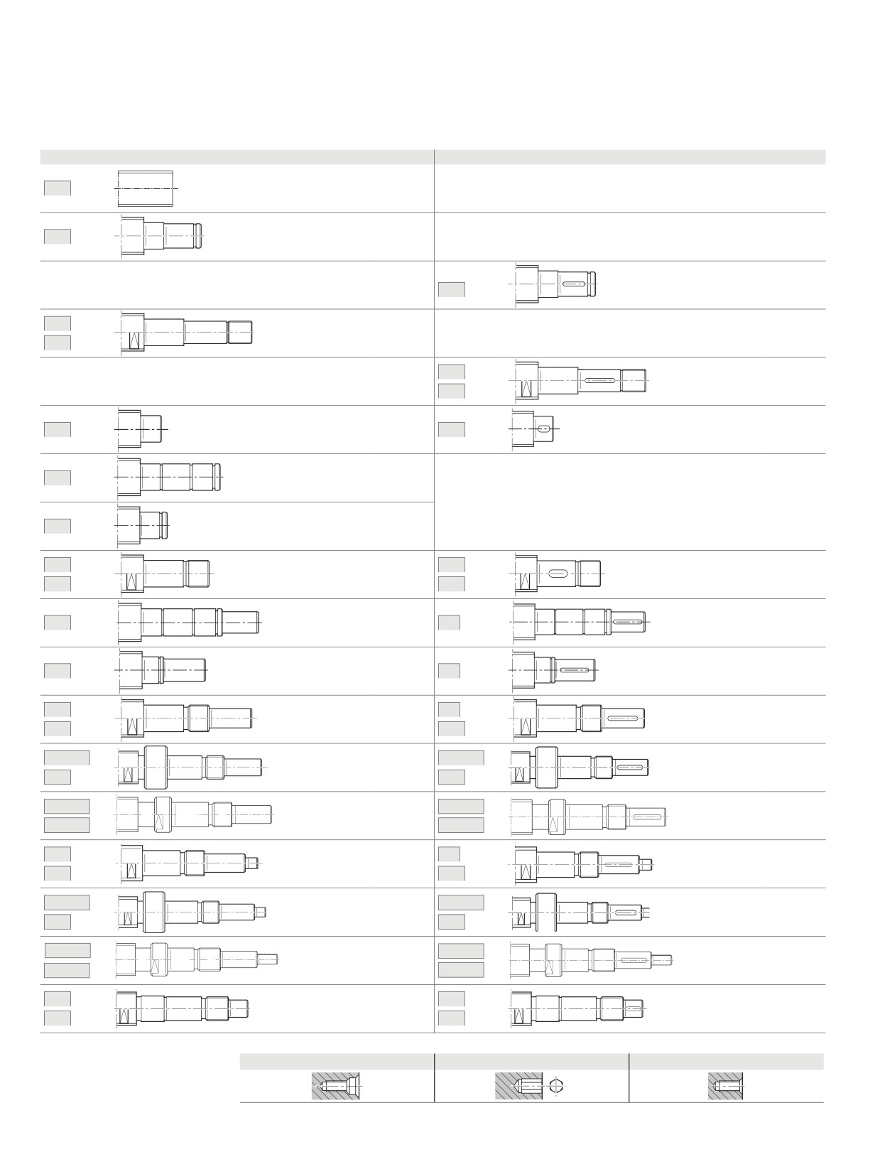
Overview of screw ends
Screw ends, forms for a left or right screw end
Basic version
with keyway
00
page 59
L1
page 60
page 62
02
K1
page 64
K1A
12
page 66
12A
21
page 68
22
page 68
31
page 70
41
page 72
51
52
page 74
page 74
51A
52A
61
page 76
62
page 76
71
page 78
72
page 78
81
82
page 80
page 80
81A
82A
831/83
841/84
page 84
page 84
83A
84A
8A
8B
page 86
page 86
8AB
8BB
91
92
page 88
page 88
91A
92A
931/93
941/94
page 90
page 90
93A
94A
9A
9B
page 92
page 92
9AB
9BB
N1
N2
page 94
page 94
N1A
N2A
End machining of end-face
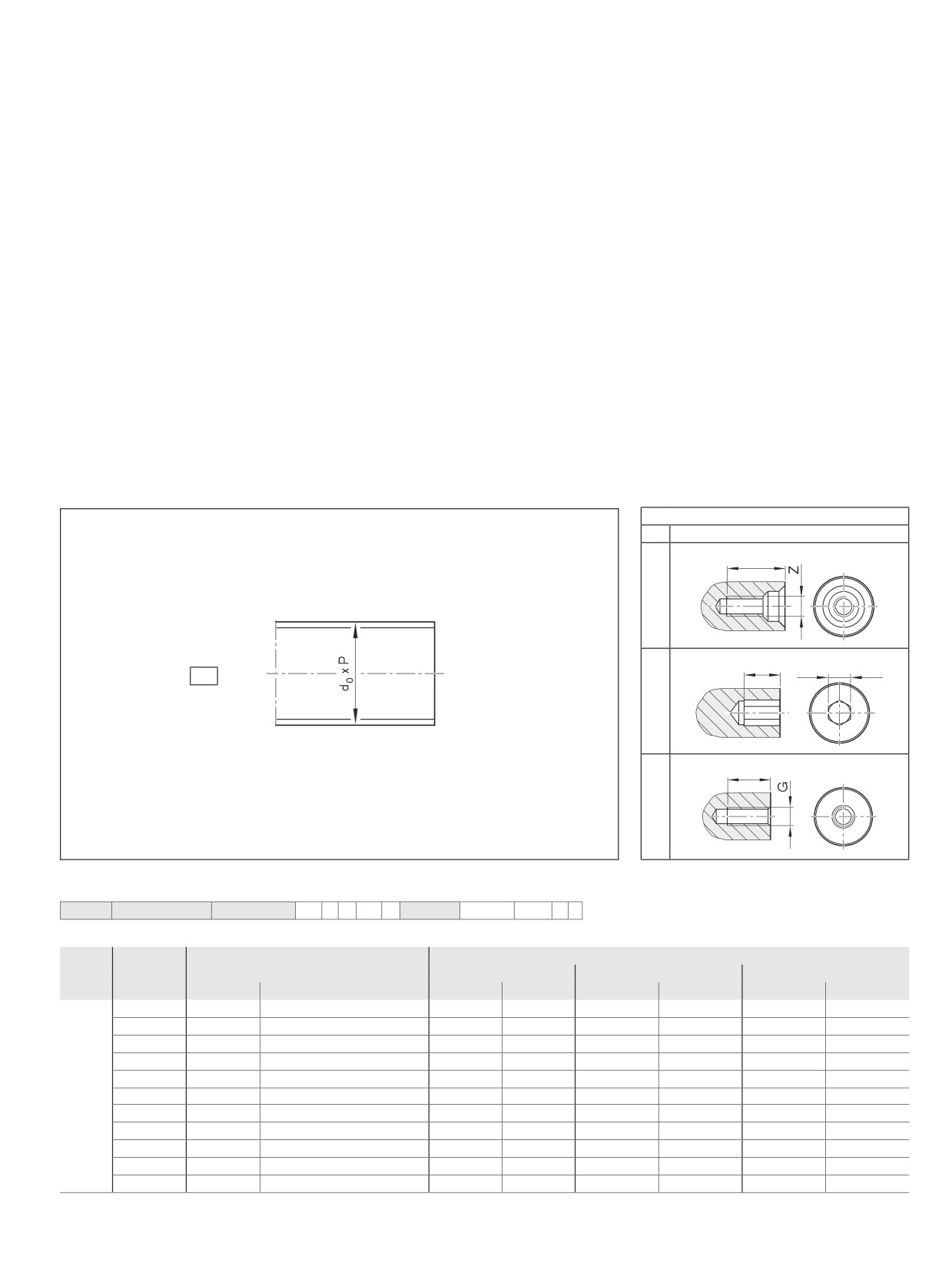
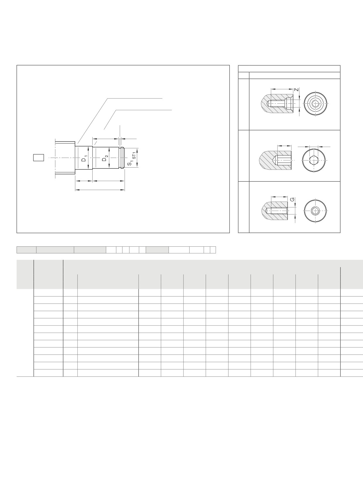
Z Centering hole DIN 332-D
S Hex socket
G Female thread
59
Screw ends
Abbreviations
C
= dynamic load rating
MAG
= tightening torque of set screw
C0
= static load rating
MRL
= bearing friction torque with seal
d0 x P = size
Mp
= maximum permissible drive torque (condition:
d0
= nominal diameter
no radial load at drive journal)
FaB
= axial breaking load of slotted nut
Rfb
= rigidity (axial)
G
= female thread
Rkl
= rigidity against tilting
nG
= limit speed (grease)
P
= lead (R = right-hand)
No.
= part number
S
= hex socket
MA
= tightening torque of slotted nut
Z
= centering hole
Form 00
Option (machining of end face)
K
None
Z
tZ
S
tS
S
00
G
tG
Ordering data:
BASA
20x5R x 3
SEM-E-S - 4
00
1
2
T7
R
00Z200
82Z120
1250
0
1
Form
Version
Size
(mm)
Centering hole
Hex socket
Thread
d0
P
Z
tZ
S
tS
G
tg
00
060
6
1/2
-
-
-
-
-
-
080
8
1/2/2.5/5
-
-
-
-
-
-
120
12
2/5/10
M3
9
4
4
M4
6
160
16
5/10/16
M4
10
5
5
M5
8
200
20
5/10/20/40
M6
16
8
8
M6
9
250
25
5/10/25
M8
19
10
10
M8
12
320
32
5/10/20/32/64
M10
22
12
12
M10
15
400
40
5/10/12/16/20/25/30/40
M12
28
14
14
M12
18
500
50
5/10/12/16/20/25/30/40
M16
36
17
17
M16
24
630
63
10/20/40
M20
42
17
17
M20
30
800
80
10/20
M20
42
19
19
M24
36
60
Screw Assemblies | Ball Screw Assemblies BASA
Screw Ends
Form L1
Option (machining of end face)
K
None
Z
tZ
Undercut Form E DIN 509
Undercut Form E DIN 509
Undercut for retaining ring DIN 471
L6
LS1
S
tS
S
L1
L1
L2
Ljl
G
tG
Ordering data:
BASA
20x5R x 3
SEM-E-S - 4
00
1
2
T7
R
02Z120
82Z120
1250
0
1
Form
Version1)
(mm)
d0
P
Ljl
D1
L1
D2
L2
L6
S1
ST1
LS1
h11
j6
H13
L1
050
8
1/2/2.5/5
17
6.0
10
5
7
5
4.8
h10
0.70
060
12
2/5/10
18
9.5
10
6
8
6
5.7
h10
0.80
100
16
5/10/16
22
12.5
10
10
12
9
9.6
h10
1.10
120
20
5/10/20/40
23
16.0
10
12
13
10
11.5
h11
1.10
150
20
5/10/20/40
24
16.0
10
15
14
11
14.3
h11
1.10
170
25
5/10/25
25
21.0
10
17
15
12
16.2
h11
1.10
200
32
5/10/20/32/64
28
27.5
10
20
18
14
19.0
h11
1.30
250
32
5/10/20/32/64
29
27.5
10
25
19
15
23.9
h12
1.30
300
40
5/10/12/16/20/25/30/40
30
33.5
10
30
20
16
28.6
h12
1.60
350
50
5/10/12/16/20/25/30/40
32
43.0
10
35
22
17
33.0
h12
1.60
500
63
10/20/40
37
56.0
10
50
27
20
47.0
h12
2.15
600
80
10/20
39
66.5
10
60
29
22
57.0
h12
2.15
1) The allocation of screw ends to the bearing assemblies is clearly defined by the version.