Takeuchi compact excavator TB125, TB135, TB145 / diesel TNE / diesel Yanmar. Service Manual - page 19
 

  Index      Manuals     Takeuchi compact excavator TB125 (12510003~), TB135 (13510004~), TB145 (14510004~) / diesel TNE / diesel Yanmar. Service Manual


Search            copyright infringement  


Content      ..     17      18      19      20     ..


Takeuchi compact excavator TB125, TB135, TB145 / diesel TNE / diesel Yanmar. Service Manual - page 19


IV-28

HYDRAULIC UNITS

HYDRAULIC PUMP

TB125, 135, 145

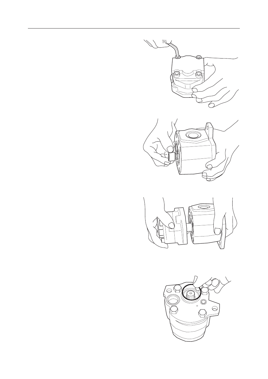
g. Fix the frame and the housing with the cap

screws.
• Cap screw tightening torque:

29 N·m (3 kgf·m)

h. Fit two pins to the frame and mount the cou-

pling on the shaft end on the side of the pump
P3.

20. Unite the pump P3 and the pump P4 and fix them

with the bolt.
• Bolt tightening torque: 59 N·m (6 kgf·m)

21. Fit the O-ring to the frame.

K3D151

K3D152

K3D153

K3D154

IV-29

HYDRAULIC UNITS

HYDRAULIC PUMP

TB125, 135, 145

22. Assemble the solenoid valve.

a. Mount the spring and spool on the body.

b. Mount the O-ring on the body.

c. Mount the solenoids on the body and fix them

with the cap screws.
• Cap screw tightening torque:

3.4~4.4 N·m (35~46 kgf·m)

d. Fit the O-ring to the body.

K3D137

K3D155

K3D136

K3D156

IV-30

HYDRAULIC UNITS

HYDRAULIC PUMP

TB125, 135, 145

23. Unite the main pump and gear pump and fix them

with the cap screws.
• Cap screw tightening torque:

55~69 N·m (5.6~7.0 kgf·m)

24. Mount the solenoid valve on the pump and fix it

with the cap screws.
• Cap screw tightening torque:

28~35 N·m (2.9~3.6 kgf·m)

K3D118

K3D117

A

IV-31

HYDRAULIC UNITS

HYDRAULIC PUMP

TB125, 135, 145

INSPECTION AND ADJUSTMENT

Checking the Parts

“IV-45”

TROUBLESHOOTING

“IV-46”

IV-32

HYDRAULIC UNITS

HYDRAULIC PUMP

TB125, 135, 145

IV-33

HYDRAULIC UNITS

HYDRAULIC PUMP

TB125, 135, 145

HYDRAULIC PUMP (TB125: S/N 12512126~, TB135)

CONSTRUCTION
TB125: S/N 12512126~
TB135: S/N 13510004~13512532

  1. Body S
  2. Body H
  3. Shaft
  4. Cylinder Block
  5. Valve Plate
  6. Piston
  7. Shoe
  8. Shoe Holder
  9. Guide
10. Swash Plate
11. Pin
12. Pin
13. Packing
14. Spring C

15. Spring T1
16. Spring Holder
17. Spring Guide
18. Pin
19. Piston
20. Washer
21. Retainer
22. Stopper Pin A
23. Stopper Pin B
24. Pin
25. Ball Bearing
26. Needle Bearing
27. Oil Seal
28. Conical Spring Washer

29. Snap Ring
30. Snap Ring
31. Snap Ring
32. O-ring
33. O-ring
34. Plug
35. O-ring
36. Bolt
37. Plug
38. Plug
39. Spring Washer
40. Spring Pin
41. Set Screw

42. Nut
43. Seal Washer
44. Gear Pump
45. Coupling
46. Collar
47. Cap Screw
48. Washer
49. O-ring
50. O-ring
51. O-ring
52. Seal Holder
53. O-ring
54. Solenoid Valve

IV-34

HYDRAULIC UNITS

HYDRAULIC PUMP

TB125, 135, 145

TB135: S/N 13512533~

  1. Body S
  2. Body H
  3. Shaft
  4. Cylinder Block
  5. Valve Plate
  6. Piston
  7. Shoe
  8. Shoe Holder
  9. Guide
10. Swash Plate
11. Pin
12. Pin
13. Packing
14. Spring C

15. Spring T1
16. Spring Holder
17. Spring Guide
18. Pin
19. Piston
20. Washer
21. Retainer
22. Stopper Pin A
23. Stopper Pin B
24. Pin
25. Ball Bearing
26. Needle Bearing
27. Oil Seal
28. Conical Spring Washer

29. Snap Ring
30. Snap Ring
31. Snap Ring
32. O-ring
33. O-ring
34. Plug
35. O-ring
36. Bolt
37. Plug
38. Plug
39. Spring Washer
40. Spring Pin
41. Set Screw

42. Nut
43. Seal Washer
44. Gear Pump
45. Coupling
46. Collar
47. Cap Screw
48. Washer
49. O-ring
50. O-ring
51. O-ring
52. Seal Holder
53. O-ring
54. Solenoid Valve

IV-35

HYDRAULIC UNITS

HYDRAULIC PUMP

TB125, 135, 145

OPERATION

Piston Pump

This pump is a variable displacement piston pump
with a single cylinder block, which discharges two
equal volumes.
Ten pistons (2) are installed in the cylinder block (1),
and the end surface is in contact with the valve plate
(3). The suction port C and the discharge port A of the
pump P1 and the discharge port B of the pump P2 are
arranged in the valve plate (3). On the other hand, the
swash plate (4) is fastened to the housing at a given
inclination, and the pistons (2) rotate along this swash
plate (4).
When the shaft (5) is rotated, the cylinder block (1)
rotates, the pistons (2) in the cylinder block execute
reciprocating movement along the swash plate (4),
and the pump executes suction and discharge. At this
time, the pistons in contact with the discharge port A
of the valve plate (3) operate as the pump P1, while the
pistons in contact with the discharge port B operate as
the pump P2.
In this way, the ten pistons (2) execute one suction and
discharge stroke with each revolution of the cylinder
block (1), so that suction and discharge are executed
continuously when the shaft (5) is rotated continu-
ously.
As the piston stroke displacement depends on the
inclination of the swash plate (4), the discharge flow
quantity can be changed by changing the inclination
of the awash plate (4).

Discharge volume control

The swash plate (4) is equipped with the swing pins
(6) and is mounted on the housing at an inclination
that can be varied. The swash plate (4) is loaded with
the pistons (2) of the cylinder block and the piston (9)
in opposition to the spring (7). The discharge pres-
sures from the pumps P1 and P2 work on the pistons
(2). The discharge pressure from the pump P3 works
on the piston (9). If the discharge pressure is below the
value preset for the spring (7), the inclination of the
swash plate (4) is fixed to the maximum value by the
spring (7).

C4D101

5

4

3

2

1

C4D102

P3

4

7

P1,P2

6

9

2

G4D101

SUCTION STROKE

DISCHAGE STROKE

C

A

B

3

1

2

4

P1

P2

IV-36

HYDRAULIC UNITS

HYDRAULIC PUMP

TB125, 135, 145

If the discharge pressure becomes larger than the
preset value for the spring (7), the inclination of the
swash plate (4) is made smaller by the resultant of the
piston's force F1 x a and the piston's force F2. The
swash plate (4) is kept at the inclination that balances
the discharge pressure and the spring force.

If the discharge pressure further increases, the incli-
nation of the swash plate (4) becomes much smaller.
At this time, the arm length "a" on which the resultant
of the piston's force F1 works decreases to "a' ".  This
means that a much larger force F1 is needed to keep
the balance.

Thus, by changing the inclination of the swash plate
(4) the discharge is controlled and only minimum
pressure and flow required for the load are supplied
from the pump. This minimizes the pressure loss of
the pump. The inclination of the swash plate (4) varies
depending on the operating pressures not only by the
pumps P1 and P2 but also by the pump P3. Thus, the
P-Q curve for the piston pumps shows that the engine's
power is fully utilized (full horse power control).

Gear Pump

The gear pump consists of a single gear case, inside of
which is a drive gear (1) and a driven gear (2) engaged
with each other. By turning the drive shaft (3), the
space between the case and the gears is filled with oil.
This oil is thus sent through the pump from the inlet
to the outlet.

C4D103

4

9

F2

a

F1

2

7

C4D104

a'

F2

9

4

7

2

F1

INLET

OUTLET

IV-37

HYDRAULIC UNITS

HYDRAULIC PUMP

TB125, 135, 145

Pilot Relief Valve and Solenoid Valve

The pilot relief valve (1) keeps the pressure in the pilot
circuit constant by releasing the oil into the tank
passage when the discharged oil pressure from the
pump P4 (2) exceeds the preset value.
This pilot pressure is switched by the solenoid valve
A (that switches the second travel speed) and the
solenoid valve B (that switches the lever lock).

Solenoid Valve

When Current is NOT Flowing
Oil at port P is blocked by the spool (1). Also, since
port A and port T are connected, the pressure in the
pilot circuit downstream becomes the same as the
tank pressure.

When Current is Flowing
A magnetic field is generated around the coil and the
plunger (2) is pulled down. This pushes the spool (1)
down. As a result, oil at port P flows into port A and
pressure is transmitted to the pilot circuit at the
bottom.

G4D103

2

PB

B

A

PA

1

P

G4D108

A

1

2

P

G4D109

T

P

A

1

IV-38

HYDRAULIC UNITS

HYDRAULIC PUMP

TB125, 135, 145

DISASSEMBLY AND ASSEMBLY

General Cautions

• Carry out disassembly and assembly operations in

a clean place and provide clean containers to place
the disassembled parts in.

• Before disassembly, clean around the ports and

remove the paint from each joint using a wire
brush.

• Clean each of the disassembled parts with a clean-

ing oil such as diesel fuel.

• Make match marks on each part so that they will be

assembled in the same positions when assembled.

• Replace all seals with new ones each time the pump

is disassembled, coating them lightly with grease.

• Check each part to make sure there is no abnormal

wear or seizing and use sandpaper, etc. to remove
any burrs, sharp edges, etc.

• Adjust adjustment screws only when required.

Disassembly

1. Remove cap screws and then the solenoid valve.

2. Remove the bolts and then the gear pump.

3. Loosen the lock nut (3) and remove the set screw

(2).
• Record the length of the set screw protrusion

before starting the disassembly.

4. Disassemble the body S and body H.

a. Remove the upper two of the five cap screws

(4), replace the two temporary cap screws
(M10 

×

 65), and tighten them by about 10 mm.

b. Slowly loosen the remaining three cap screws

(4).

c. Loosen the temporary cap screws (M10 

×

 65)

and separate the body S from the body H.
• Lightly tap the spring insert section of the

body H with a plastic hammer.

G4D104

G4D105

3

2

IV-39

HYDRAULIC UNITS

HYDRAULIC PUMP

TB125, 135, 145

5. Remove the spring (5) and spring holder (6) of the

body H from the body S.

6. Remove the cylinder block from the body S.

7. Remove the swash plate (7) and swing pins (8)

from the body S.

8. Remove the stopper pin A and the washers, then

the stopper pin B and the washers and piston from
the body S.
• Parts should be stored so that they can be

placed at the same positions when they are
assembled.

9. Remove the snap ring from the shaft side of the

body S.

10. Remove the shaft assembly and oil seal from the

body S.
• Use a plastic hammer to take off the shaft

assembly.

C4D108

7

8

C4D107

5

6

IV-40

HYDRAULIC UNITS

HYDRAULIC PUMP

TB125, 135, 145

11. Remove the spring guide (9) and valve plate (10)

from the body H.
• To remove the spring guide, drive the set screw

into the set screw hole of the body H and push
out the spring guide.

12. Disassemble the cylinder block.

a. Remove the shoe holder (11) and guide (12)

from the cylinder block.

b. Remove the shoe holder (11) from the pistons

(13).

c. Remove the pins (14) from the cylinder block.

d. Remove the snap ring (15) first, and then the

retainer (16), spring (17) and retainer (16)
from the cylinder block.

C4D110

11

12

13

C4D111

14

C4D112

C4D113

15

16

17

C4D109

10

9

IV-41

HYDRAULIC UNITS

HYDRAULIC PUMP

TB125, 135, 145

Assembly

1. Mount the shaft assembly (18), oil seal (19) and

snap ring (20) on the body S.
• To mount the oil seal (19), use the insertion jig

(A) (see Figure below) and tap the oil seal
lightly with a hammer.

• Temporarily mount the body S on the body H.

2. Fit two conical spring washers (22) and the washer

(23) to the stopper pin A (21), and mount them on
the body S.

3. Fit two conical spring washers (25) and the washer

(26) to the stopper pin B (24), and mount them on
the body S.

4. Mount the piston (27) on the body S.

5. Fit the swing pins (8) to the swash plate, and

install it into the ball orifice of the body S.

6. Assemble the cylinder block assembly.

a. Install the retainer (16), spring (17), retainer

(16) and snap ring (15).

C4D113

15

16

17

C4D112

C4D108

7

8

UNIT: mm

MATERIAL: S35C OR EQUIVALENT

G4D106

24

26

25

18

20

27

21

23

22

19

IV-42

HYDRAULIC UNITS

HYDRAULIC PUMP

TB125, 135, 145

b. Fit the pin (14) to the cylinder block.

c. Fit the guide (12) to the cylinder block.
d. Fit the pistons (13) to the shoe holder (11), and

mount the shoe holder on the cylinder block.

7. Mount the cylinder block assembly on the body S.

8. Fit the spring (5) to the spring holder (6). Then,

install the ball-shaped section of the spring holder
in the orifice of the swash plate.

C4D111

14

C4D110

11

12

13

C4D107

5

6

IV-43

HYDRAULIC UNITS

HYDRAULIC PUMP

TB125, 135, 145

9. Mount the spring guide (9) on the body H.

10. Position the valve plate (10) by the spring pin of

the body H and gently fix it.
• Be careful of the direction of the valve plate.

The whiskered surface of the valve plate should
be circled along the cylinder block.

11. Fit the packing to the mating surface of the body

S.
• The packing should be aligned with the posi-

tioning pin of the body S.

12. Fit two temporary cap screws (M10 

×

 65) to the

upper side and tighten them slowly. When the
clearance between the two surfaces becomes 5
mm to 10 mm, replace the temporary cap screws
with five cap screws (M10 

×

 45) and fix them.

Cap Screw: 51.0~64.7 N·m

13. Install the set screw (2).

• Fix the set screw (2) to the same length as

previously assembled using the lock nut (3).

14. Fit the collar (28) and coupling (29) to the gear

pump connection position of the piston pump,
and fit the O-rings (30) and (31).

C4D109

10

9

G4D107

31

30 28 29


Content      ..     17      18      19      20     ..