TC65i AT-Commands Set. Manual - part 1
TC65i
Version:
01.100
DocId:
01.100
Date:
November 10, 2008
DocId:
THE USE OF THE PRODUCT INCLUDING THE SOFTWARE AND DOCUMENTATION (THE "PRODUCT") IS
SUBJECT TO THE RELEASE NOTE PROVIDED TOGETHER WITH PRODUCT. IN ANY EVENT THE PROVI-
SIONS OF THE RELEASE NOTE SHALL PREVAIL. THIS DOCUMENT CONTAINS INFORMATION ON CIN-
TERION PRODUCTS. THE SPECIFICATIONS IN THIS DOCUMENT ARE SUBJECT TO CHANGE AT
CINTERION'S DISCRETION. CINTERION WIRELESS MODULES GMBH GRANTS A NON-EXCLUSIVE
RIGHT TO USE THE PRODUCT. THE RECIPIENT SHALL NOT TRANSFER, COPY, MODIFY, TRANSLATE,
REVERSE ENGINEER, CREATE DERIVATIVE WORKS; DISASSEMBLE OR DECOMPILE THE PRODUCT
OR OTHERWISE USE THE PRODUCT EXCEPT AS SPECIFICALLY AUTHORIZED. THE PRODUCT AND
THIS DOCUMENT ARE PROVIDED ON AN "AS IS" BASIS ONLY AND MAY CONTAIN DEFICIENCIES OR
INADEQUACIES. TO THE MAXIMUM EXTENT PERMITTED BY APPLICABLE LAW, CINTERION WIRELESS
MODULES GMBH DISCLAIMS ALL WARRANTIES AND LIABILITIES. THE RECIPIENT UNDERTAKES FOR
AN UNLIMITED PERIOD OF TIME TO OBSERVE SECRECY REGARDING ANY INFORMATION AND DATA
PROVIDED TO HIM IN THE CONTEXT OF THE DELIVERY OF THE PRODUCT. THIS GENERAL NOTE
SHALL BE GOVERNED AND CONSTRUED ACCORDING TO GERMAN LAW.
Copyright
Transmittal, reproduction, dissemination and/or editing of this document as well as utilization of its contents and
communication thereof to others without express authorization are prohibited. Offenders will be held liable for
payment of damages. All rights created by patent grant or registration of a utility model or design patent are
reserved.
Copyright © 2008, Cinterion Wireless Modules GmbH
Trademark Notice
BluetoothTM is a registered trademark of Bluetooth SIG Inc.
Microsoft and Windows are either registered trademarks or trademarks of Microsoft Corporation in the United
States and/or other countries. All other registered trademarks or trademarks mentioned in this document are
property of their respective owners.
Contents
1.
Introduction
14
1.1
Scope of the document
14
1.2
Related documents
15
1.3
Document conventions
16
1.3.1
Quick reference table
16
1.3.2
Superscript notation for parameters and values
17
1.4
AT Command Syntax
18
1.4.1
Using Parameters
18
1.4.2
Concatenating AT Commands
19
1.5
Communication between Customer Application and TC65i
20
1.6
Supported character sets
21
1.6.1
GSM alphabet tables and UCS2 character values
22
1.6.2
UCS2 and GSM data coding and conversion for SMS text mode and Remote SAT
24
1.6.2.1
Implementing output of SIM data to Terminal (direction TA to TE)
24
1.6.2.2
Implementing input of Terminal data to SIM (direction TE to TA)
25
1.7
Unsolicited Result Code Presentation
26
1.8
Errors and Messages
27
1.9
Auxiliary Serial Interface
28
1.10
Serial Interface Flow Control
29
1.10.1
Software Flow Control (XON/OFF Handshake)
29
1.10.2
Hardware Flow Control (RTS/CTS Handshake)
29
1.11
Common PCN Handset Specification (CPHS)
31
2.
Configuration Commands
32
2.1
AT&F Set all current parameters to manufacturer defaults
32
2.2
AT&V Display current configuration
33
2.2.1
AT&V responses
34
2.3
AT&W Stores current configuration to user defined profile
36
2.4
ATQ Result code presentation mode
37
2.5
ATV Result code format mode
38
2.5.1
Verbose and numeric result codes
38
2.6
ATX Set CONNECT result code format and call monitoring
39
2.7
AT\V Set CONNECT result code format
40
2.8
ATZ Set all current parameters to user defined profile
41
2.9
AT+CFUN Set phone functionality
42
2.9.1
Wake up the ME from SLEEP mode
45
2.10
AT^SMSO Switch off mobile station
46
2.11
AT+GCAP Request complete TA capabilities list
47
2.12
AT+CMEE Mobile Equipment Error Message Format
48
2.12.1
CME/CMS Error Code Overview
49
2.13
AT+CSCS Select TE character set
56
2.14
AT^SCFG Extended Configuration Settings
57
2.15
AT^SM20
Set M20 compatibility mode
83
3.
Status Control Commands
84
3.1
AT+CMER Mobile Equipment Event Reporting
84
3.2
AT+CIND Indicator control
86
3.3
AT^SIND Extended Indicator Control
89
3.4
AT+CEER Extended Error Report
98
3.4.1
Cause Location ID for the extended error report
99
3.4.2
Proprietary L2 cause
100
3.4.3
GSM release cause for L3 Radio Resource (RR)
100
3.4.4
Proprietary release cause for L3 Radio Resource (RR)
101
3.4.5
GSM release cause for Mobility Management (MM) or Session Management (SM)... 101
3.4.6
Proprietary release cause for L3 Mobility Management (MM)
102
3.4.7
GSM release cause for L3 Call Control (CC)
103
3.4.8
Proprietary release cause for L3 Call Control (CC)
104
3.4.9
GSM Release cause for Supplementary Service Call
104
3.4.10
GSM release cause for Session Management (SM)
106
3.4.11
GSM cause for L3 Protocol module or other local cause
106
3.4.12
Proprietary release cause for GPRS API
106
3.4.13
Proprietary release cause for PPP/IP-Stack
106
3.5
ATS18
Extended call release report
107
3.6
AT+CPAS Mobile equipment activity status
109
3.7
AT+WS46
Select wireless network
110
4.
Serial Interface Control Commands
111
4.1
ATE Enable command echo
111
4.2
AT&C Set Data Carrier Detect (DCD) Line mode
112
4.3
AT&D Set Data Terminal Ready (DTR) line mode
113
4.4
AT&S Set Data Set Ready (DSR) line mode
114
4.5
AT\Q Flow control
115
4.6
AT+IFC Flow Control
116
4.7
AT+ICF Character Framing
118
4.8
AT+ILRR Set TE-TA local rate reporting
120
4.9
AT+IPR Bit Rate
122
4.9.1
Autobauding
123
4.10
AT+CMUX Multiplex Mode
125
4.10.1
Restrictions on Multiplex mode
126
4.11
AT^STPB Transmit Parity Bit (for 7E1 and 7O1 only)
128
5.
Security Commands
129
5.1
AT+CPIN PIN Authentication
129
5.1.1
What to do if PIN or password authentication fails?
131
5.2
AT+CPIN2
PIN2 Authentication
133
5.3
AT^SPIC Display PIN counter
135
5.4
AT+CLCK Facility lock
139
5.5
AT^SLCK Facility lock
144
5.6
AT+CPWD Change Password
145
5.7
AT^SPWD Change Password
149
5.8
AT^SCSL Customer SIM Lock
151
6.
Identification Commands
155
6.1
ATI Display product identification information
155
6.2
AT+CGMI Request manufacturer identification
156
6.3
AT+GMI Request manufacturer identification
156
6.4
AT+CGMM Request model identification
157
6.5
AT+GMM Request model identification
157
6.6
AT+CGMR Request revision identification of software status
158
6.7
AT+GMR Request revision identification of software status
158
6.8
AT+CGSN Request International Mobile Equipment Identity (IMEI)
159
6.9
AT+GSN Request International Mobile Equipment Identity (IMEI)
159
6.10
AT+CIMI Request International Mobile Subscriber Identity (IMSI)
160
7.
Call related Commands
161
7.1
Call Status Information
161
7.2
ATA Answer a call
162
7.3
ATD Mobile originated call to specified number
163
7.4
ATD><mem><n> Mobile originated call using specific memory and index number
165
7.5
ATD><n> Mobile originated call from active memory using index number
167
7.6
ATD><str> Mobile originated call from active memory using corresponding field
168
7.7
ATDI Mobile originated call to ISDN number
169
7.8
ATDL Redial last number used
170
7.9
ATH Disconnect existing connection
171
7.10
AT+CHUP Hang up call
172
7.11
AT^SHUP Hang up call(s) indicating a specific GSM04.08 release cause
173
7.12
ATS0
Set number of rings before automatically answering a call
175
7.13
ATS2
Set escape sequence character
176
7.14
ATS6
Set pause before blind dialing
177
7.15
ATS7
Set number of seconds to wait for connection completion
178
7.16
ATS8
Set number of seconds to wait for comma dialing modifier
179
7.17
ATS10
Set disconnect delay after indicating the absence of data carrier
180
7.18
ATO Switch from command mode to data mode / PPP online mode
181
7.19
+++ Switch from data mode or PPP online mode to command mode
182
7.20
AT+CBST Select bearer service type
183
7.21
AT+CRLP Select radio link protocol parameters for originated non-transparent data calls
185
7.22
AT+CLCC List of current calls
186
7.23
AT^SLCC Extended list of current calls
188
7.24
AT+CR Service reporting control
193
7.25
AT+CRC Set Cellular Result Codes for incoming call indication
194
7.26
AT+CSNS Single Numbering Scheme
195
7.27
AT^SCNI List Call Number Information
196
7.28
AT^SLCD Display Last Call Duration
197
7.29
AT^STCD Display Total Call Duration
198
7.30
ATP Select pulse dialing
199
7.31
ATT Select tone dialing
199
8.
Network Service Commands
200
8.1
AT+COPN Read operator names
200
8.2
AT+COPS Operator Selection
201
8.3
AT^SOPS Extended Operator Selection
204
8.4
AT+CREG Network registration
206
8.5
AT+CSQ Signal quality
209
8.6
AT^SMONC Cell Monitoring
210
8.7
AT^SMOND Cell Monitoring
212
8.8
AT^SFNUR Select the fixed network user rate
215
8.9
AT^MONI Monitor idle mode and dedicated mode
216
8.9.1
AT^MONI responses
217
8.9.2
Service states
218
8.10
AT^MONP Monitor neighbor cells
219
8.10.1
AT^MONP responses
220
8.11
AT^SMONG GPRS Monitor
221
8.11.1
AT^SMONG Cell Info Table
222
8.12
AT^SALS Alternate Line Service
223
8.13
AT^SHOM Display Homezone
225
8.14
AT^SPLM Read the PLMN list
226
8.15
AT+CPOL Preferred Operator List
228
9.
Supplementary Service Commands
229
9.1
AT+CACM Accumulated call meter (ACM) reset or query
229
9.2
AT^SACM Advice of charge and query of ACM and ACMmax
230
9.3
AT+CAMM Accumulated call meter maximum (ACMmax) set or query
232
9.4
AT+CAOC Advice of Charge information
233
9.5
AT+CCUG Closed User Group
234
9.6
AT+CCFC Call forwarding number and conditions control
236
9.7
AT+CCWA Call Waiting
240
9.8
AT+CHLD Call Hold and Multiparty
244
9.9
AT+CLIP Calling Line Identification Presentation
246
9.10
AT+CLIR Calling Line Identification Restriction
248
9.11
AT+COLP Connected Line Identification Presentation
249
9.12
AT+CPUC Price per unit and currency table
251
9.13
AT+CSSN Supplementary service notifications
253
9.14
AT+CUSD Unstructured supplementary service data
255
10.
Internet Service Commands
257
10.1
AT^SICS Internet Connection Setup Profile
260
10.1.1
Example: Default values of a CSD connection profile
263
10.1.2
Example: GPRS connection profile
264
10.2
AT^SICI Internet Connection Information
265
10.2.1
Checking Connection Profile Status
266
10.3
AT^SISS Internet Service Setup Profile
268
10.4
AT^SISI Internet Service Information
277
10.5
AT^SISO Internet Service Open
279
10.5.1
Example: Accepting / Rejecting Socket Connection Request from Remote Client
283
10.6
AT^SISC Internet Service Close
285
10.7
AT^SISR Internet Service Read Data
286
10.7.1
Example: Socket Host Reads Small Amounts of UDP Data Packets (URC Mode)
288
10.8
AT^SISW Internet Service Write Data
289
10.8.1
Usage of parameter <eodFlag>
291
10.9
AT^SICO Internet Connection Open
293
10.10 AT^SICC Internet Connection Close
295
10.11 AT^SISX Internet Service Execution
296
10.11.1
Example: Ping
298
10.12 AT^SISE Internet Service Error Report
299
10.13 Internet Service URC "^SIS"
300
10.13.1
Information Elements Related to the Service Application
301
10.13.2
Information Elements Related to FTP Service
302
10.13.3
Information Elements Related to HTTP Service
303
10.13.4
Information Elements Related to POP3 Service
303
10.13.5
Information Elements Related to SMTP Service
303
10.14 Examples of how to Configure and Use Internet Service Profiles
304
10.14.1
Selecting URC Mode or Polling Mode
304
10.14.2
Configuring Socket Listener
304
10.14.3
Configuring Socket Client for Calling a Socket Listener on Another Host
305
10.14.4
Socket Client Sends Data via TCP Connection (Polling Mode)
305
10.14.5
Socket client sends data via TCP connection with URCs
306
10.14.6
Socket Scenario with UDP Endpoint
306
10.14.7
Configuring and Using FTP Download (URC Mode)
308
10.14.8
Configuring and Using FTP Upload (URC Mode)
308
10.14.9
Configuring SMPT Service Profile
309
10.14.10 Sending Email (URC Mode)
310
10.14.11 Sending Email (Polling Mode)
310
10.14.12 Configuring POP3 Service Profile
311
10.14.13 Retrieving Email (URC Mode)
313
10.14.14 Retrieving Email (Polling Mode)
313
10.14.15 HTTP POST (Polling Mode)
314
10.14.16 HTTP GET (Polling Mode)
315
11.
GPRS Commands
316
11.1
AT+CGACT PDP context activate or deactivate
316
11.2
AT+CGANS Manual response to a network request for PDP context activation
318
11.3
AT+CGATT GPRS attach or detach
320
11.4
AT+CGAUTO Automatic response to a network request for PDP context activation
321
11.5
AT+CGDATA Enter data state
323
11.5.1
Automatic deactivation of PDP context during dial-up PPP
324
11.6
AT+CGDCONT Define PDP Context
325
11.7
AT+CGEQMIN Rel. 99 Quality of Service Profile (Minimum acceptable)
327
11.8
AT+CGEQREQ Rel. 99 Quality of Service Profile (Requested)
331
11.9
AT+CGPADDR Show PDP address
335
11.10
AT+CGQMIN Quality of Service Profile (Minimum acceptable)
336
11.11
AT+CGQREQ Quality of Service Profile (Requested)
340
11.12
AT+CGREG GPRS Network Registration Status
344
11.13
AT+CGSMS Select service for MO SMS messages
346
11.14
AT^SGACT Query all PDP context activations
347
11.15
AT^SGAUTH Set type of authentication for PPP connection
349
11.16
AT^SGCONF Configuration of GPRS related Parameters
350
11.17
ATA Manual response to a network request for PDP context activation
351
11.18
ATD*99# Request GPRS service
352
11.19
ATD*98# Request GPRS IP service
353
11.20
ATH Manual rejection of a network request for PDP context activation
354
11.21
ATS0
Automatic response to a network request for PDP context activation
355
11.22
Using GPRS AT commands (Examples)
356
11.23
Using the GPRS dial command ATD
358
12.
FAX Commands
359
12.1
FAX parameters
359
12.1.1
Fax Result Codes
359
12.2
AT+FCLASS Fax: Select, read or test service class
360
12.3
AT+FRH Receive Data Using HDLC Framing
361
12.4
AT+FRM Receive Data
362
12.5
AT+FRS Receive Silence
363
12.6
AT+FTH Transmit Data Using HDLC Framing
364
12.7
AT+FTM Transmit Data
365
12.8
AT+FTS Stop Transmission and Wait
366
13.
Short Message Service (SMS) Commands
367
13.1
SMS parameters
367
13.2
AT+CMGC Send an SMS command
372
13.3
AT+CMGD Delete short message
373
13.4
AT+CMGF Select SMS message format
374
13.5
AT+CMGL List SMS messages from preferred store
375
13.6
AT+CMGR Read SMS messages
377
13.7
AT+CMGS Send Short Message
379
13.8
AT+CMGW Write Short Messages to Memory
381
13.9
AT+CMSS Send short messages from storage
383
13.10
AT+CNMA New Message Acknowledgement to ME/TE, only phase 2+
384
13.11
AT+CNMI New short Message Indication
385
13.12
AT+CPMS Preferred SMS message storage
388
13.13
AT+CSCA SMS Service Center Address
390
13.14
AT+CSCB Select Cell Broadcast Message Indication
391
13.15
AT+CSDH Show SMS text mode parameters
392
13.16
AT+CSMP Set SMS text Mode Parameters
393
13.17
AT+CSMS Select Message Service
395
13.18
AT^SCML List Concatenated Short Messages from preferred store
397
13.19
AT^SCMR Read Concatenated Short Messages
398
13.20
AT^SCMS Send Concatenated Short Messages
399
13.21
AT^SCMW Write Concatenated Short Messages to Memory
400
13.22
AT^SLMS List SMS Memory Storage
401
13.23
AT^SMGL List Short Messages from preferred store without setting status to REC READ
402
13.24
AT^SMGO Set or query SMS overflow presentation mode or query SMS overflow
403
13.25
AT^SMGR Read short message without setting status to REC READ
405
13.26
AT^SSCONF SMS Command Configuration
406
13.27
AT^SSDA Set SMS Display Availability
407
13.28
AT^SSMSS Set Short Message Storage Sequence
408
14.
SIM related Commands
409
14.1
AT+CRSM Restricted SIM Access
409
14.2
AT+CSIM Generic SIM Access
412
14.3
AT^SATR Query SIM's Answer to Reset Data
414
14.4
AT^SXSM Extended SIM Access
415
14.5
AT^SCKS Query SIM and Chip Card Holder Status
417
14.6
AT^SSET Indicate SIM data ready
419
14.7
AT^SCID Display SIM card identification number
420
14.8
AT+CXXCID Display card ID
421
15.
Remote SIM Access (RSA) Commands
422
15.1
AT^SRSA Remote SIM Access Activation
425
15.2
AT^SRSM Remote SIM Access Message
429
15.2.1
SAP Request Message Parameters
432
15.2.2
SAP Response Message Parameters
432
15.3
Related AT Commands
433
15.3.1
Establishing an RSA Connection in a PC Environment
433
15.3.2
Bluetooth scenario (SAP)
433
15.3.3
Serial Interface Scenario (XSAP)
434
15.3.4
RSA Connection via Java application
434
16.
SIM Application Toolkit (SAT) Commands
435
16.1
AT^SSTA SAT Interface Activation
435
16.2
^SSTN SAT Notification
437
16.3
AT^SSTGI SAT Get Information
438
16.4
AT^SSTR SAT Response
439
17.
Phonebook Commands
441
17.1
Sort Order for Phonebooks
441
17.2
AT+CNUM Read own numbers
442
17.3
AT+CPBR Read from Phonebook
443
17.4
AT+CPBS Select phonebook memory storage
446
17.5
AT+CPBW Write into Phonebook
448
17.6
AT^SPBW Write into Phonebook with location report
451
17.7
AT^SDLD Delete the 'last number redial' memory
454
17.8
AT^SPBC Find first matching entry in sorted phonebook
455
17.9
AT^SPBD Purge phonebook memory storage
456
17.10 AT^SPBG Display phonebook entries in alphabetical order
457
17.11 AT^SPBS Step through the selected phonebook alphabetically
460
18.
Audio Commands
464
18.1
Audio programming model
464
18.2
ATL Set monitor speaker loudness
465
18.3
ATM Set monitor speaker mode
465
18.4
AT+CLVL Loudspeaker volume level
466
18.5
AT+CMUT Mute control
467
18.6
AT+VTD Tone duration
468
18.7
AT+VTS DTMF and tone generation
469
18.8
AT^SAIC Audio Interface Configuration
470
18.9
AT^SNFA Set or query of microphone attenuation
472
18.10 AT^SNFD Set audio parameters to manufacturer default values
474
18.11 AT^SNFG Generate Tone
475
18.12 AT^SNFI Set microphone path parameters
477
18.13 AT^SNFM Set microphone audio path and power supply
478
18.14 AT^SNFO Set audio output (= loudspeaker path) parameter
480
18.15 AT^SNFPT Set progress tones
482
18.16 AT^SNFS Select audio hardware set
483
18.17 AT^SNFTTY Signal TTY/CTM audio mode capability
486
18.18 AT^SNFV Set loudspeaker volume
488
18.19 AT^SNFW Write audio setting in non-volatile store
489
18.20 AT^SRTC Ring tone configuration
490
19.
Hardware related Commands
492
19.1
AT+CCLK Real Time Clock
492
19.2
AT+CALA Set alarm time
493
19.3
AT^SBC Battery Charge Control
496
19.3.1
Responses returned by read command
498
19.4
AT^SBV Battery/Supply Voltage
499
19.5
AT^SCTM Set critical operating temperature presentation mode or query temperature
500
19.5.1
Deferred shutdown
502
19.6
AT^SSYNC Configure SYNC Pin
503
19.6.1
ME status indicated by status LED patterns
504
19.7
AT^SSPI Serial Protocol Interface
506
19.7.1
Specifying Delay Time for I²C
508
19.7.2
Selecting SPI Mode
509
19.7.3
Transmitting Data over AT Interface
510
19.7.3.1
Structure of Messages on the I²C Bus
511
19.7.3.2
Structure of Messages on the SPI
512
19.7.4
Error Handling on the I²C Bus
512
19.7.5
Example: Using I²C Bus
514
19.7.6
Example: Transfer and Response Messages on SPI
515
19.8
AT^SAADC Show ADC Adjustment Values
516
19.9
AT^SRADC Configure and Read ADC Measurement
518
19.10 AT^SWDAC Configure and Read PWM Signal for DAC
521
20.
GPIO Commands
523
20.1
AT^SPIO General Purpose IO Driver Open/Close
523
20.2
AT^SCPIN Pin Configuration
524
20.3
AT^SCPOL Polling Configuration
526
20.4
AT^SCPORT Port Configuration
528
20.5
AT^SDPORT Delete a Port Configuration
529
20.6
AT^SGIO Get IO state of a specified pin or port
530
20.7
AT^SSIO Set IO state of a specified pin or port
531
20.8
AT^SCCNT Configure Pulse Counter
532
20.8.1
Using the Pulse Counter in Limit Counter Mode
533
20.9
AT^SSCNT Start and Stop Pulse Counter
534
20.9.1
Using the Pulse Counter in Start-Stop Counter Mode
535
21.
Java related Commands
536
21.1
AT^SJRA Run Java Application
536
21.2
AT^SJNET Set Dialup Network Access Parameters
537
21.3
AT^SJOTAP Over The Air Application Provisioning
540
21.4
AT^SJSEC Write Binary Java Security Data
543
22.
Miscellaneous Commands
545
22.1
A/ Repeat previous command line
545
22.2
ATS3
Set command line termination character
546
22.3
ATS4
Set response formatting character
547
22.4
ATS5
Write command line editing character
548
22.5
AT^SFDL Enter Firmware Download Mode
549
23.
Appendix
551
23.1
Restricted access to SIM data after SIM PIN authentication
551
23.2
Star-Hash (*#) Network Commands
552
23.3
Available AT Commands and Dependency on SIM PIN
555
23.4
Availability of AT Commands Depending on Operating Mode of ME
562
23.5
AT Command Settings storable with AT&W
570
23.6
Factory Default Settings Restorable with AT&F
573
23.7
Summary of Unsolicited Result Codes (URC)
576
23.8
AT Commands not usable for USB
579
23.9
Alphabetical List of AT Commands
580
List of Tables
Table
1.1:
Symbols used to mark the type of parameters
17
Table
1.2:
Symbols used to indicate the correlations with other commands
17
Table
1.3:
Symbols used to mark different types of default values of parameters
17
Table
1.4:
Types of AT commands and responses
18
Table
1.5:
Examples for character definitions depending on alphabet
21
Table
2.1:
Current configuration on ASC0 / MUX channel 1 / USB (example)
34
Table
2.2:
Current configuration on ASC1 and MUX channels 2 and 3 (example)
35
Table
2.3:
Wake-up events in NON-CYCLIC and CYCLIC SLEEP modes
45
Table
2.4:
General "CME ERROR" Codes (GSM 07.07)
49
Table
2.5:
General "CME ERROR" Codes (proprietary)
50
Table
2.6:
GPRS related "CME ERROR" Codes (GSM 07.07)
51
Table
2.7:
GPRS related "CME ERROR" Codes (proprietary)
51
Table
2.8:
SMS related "CMS ERROR" Codes (GSM 07.05)
53
Table
2.9:
Java related "CME ERROR" Codes (proprietary)
55
Table
4.1:
Availability of AT Commands on Virtual Channels
126
Table
4.2:
Summary of AT commands with Different Behavior in Multiplex Mode
127
Table
10.1:
Applicability of AT^SICS <conParmTag> values
260
Table
10.2:
Applicability of AT^SISS <srvParmTag> values
268
Table
12.1:
Fax Result Codes
359
Table
19.1:
Modes of the LED and indicated ME functions
504
Table
19.2:
Values for calculating the delay
508
Table
19.3:
Special characters for ASCII coding
510
Table
19.4:
Structure of Transfer and Response Messages on the I²C bus
511
Table
19.5:
Structure of Transfer and Response Messages for SPI
512
Table
23.1:
Star-Hash (*#) Command Overview
552
Table
23.2:
Abbreviations of Codes and Parameters used in Table 23.1
553
Table
23.3:
Star-Hash Command Response Parameters
554
Table
23.4:
Star-Hash Commands for Supplementary Services
554
Table
23.5:
Available AT Commands and Dependency on SIM PIN
555
Table
23.6:
Availability of AT Commands Depending on Operating Mode of ME
562
Table
23.7:
Settings Stored to User Profile on ASC0 / MUX Channel 1
570
Table
23.8:
Settings Stored to User Profile on ASC1 / MUX Channels 2 and 3
571
Table
23.9:
Factory Default Settings Restorable with AT&F
573
Table
23.10:
Summary of Unsolicited Result Codes (URC)
576
Table
23.11:
AT Commands not usable for USB
579
Table
23.12:
Alphabetical List of AT Commands
580
List of Figures
Figure 1.1:
Main character table of GSM 03.38 alphabet
22
Figure 1.2:
Extension character table of GSM 03.38 alphabet
23
Figure 15.1:
Basic Remote SIM Access Usage Scenario via Bluetooth
422
Figure 15.2:
Basic Remote SIM Access usage scenario via RS232
422
Figure 15.3:
SIM usage states of SAP server
423
Figure 15.4:
SIM usage states of SAP client
424
Figure 18.1:
Audio programming model for TC65i Module
464
Figure 19.1:
Formula for calculating the delay
508
Figure 19.2:
Delay time on I²C after Write
508
Figure 19.3:
Delay time on I²C after Read
508
Figure 19.4:
SPI modes selectable on SPI
509
1.
Introduction
1.1
Scope of the document
This document presents the AT Command Set for
TC65i Release 01.100.
Before using the product or upgrading to a new firmware version please read the latest product information pro-
vided in the Release Notes [1].
More information is available at http://www.cinterion.com.
1.2
Related documents
[1]
TC65i Release Notes, Version 01.100
[2]
TC65i Hardware Interface Description, Version 01.100
[3]
Java User's Guide
[4]
Remote-SAT User's Guide
[5]
GPRS Startup User's Guide
[6]
Multiplexer User's Guide
[7]
3GPP TS 27.010 (GSM 07.10): Terminal Equipment to User Equipment (TE-UE) multiplexer protocol
[8]
Multiplex Driver Developer's Guide for Windows 2000 and Windows XP
[9]
Multiplex Driver Installation Guide for Windows 2000 and Windows XP
[10]
Application Note 02: Audio Interface Design
[11]
Application Note 16: Updating TC65i Firmware
[12]
Application Note 17: Over-The-Air Firmware Update
[13]
Application Note 22: Using TTY / CTM equipment with TC65i
[14]
Application Note 24: Application Developer's Guide
[15]
Application Note 32: Integrating USB into GSM Applications
[16]
ISO/IEC10646: "Universal Multiple-Octet Coded Character Set (UCS)"; UCS2, 16 bit coding
[17]
ITU-T Recommendation V.24: List of definitions for interchange circuits between data terminal equipment
(DTE) and data circuit-terminating equipment (DCE)
[18]
ITU-T Recommendation V.250: Serial asynchronous automatic dialling and control
[19]
3GPP TS 100 918/EN 300 918 (GSM 02.04): General on supplementary services
[20]
3GPP TS 100 907 (GSM 02.30): Man-Machine Interface (MMI) of the Mobile Station (MS)
[21]
3GPP TS 23.038 (GSM 03.38): Alphabets and language specific information
[22]
3GPP TS 27.005 (GSM 07.05): Use of Data Terminal Equipment - Data Circuit terminating Equipment (DTE
- DCE) interface for Short Message Service (SMS) and Cell Broadcast Service (CBS)
[23]
3GPP TS 27.007 (GSM 07.07): AT command set for User Equipment (UE)
[24]
3GPP TS 27.060 (GSM 07.60): Mobile Station (MS) supporting Packet Switched Services
[25]
3GPP TS 51.011 (GSM11.11): Specification of the Subscriber Identity Module - Mobile Equipment (SIM -
ME) interface
[26]
3GPP TS 11.14 (GSM 11.14): Specification of the SIM Application Toolkit for the Subscriber Identity Module
- Mobile Equipment (SIM - ME) interface
[27]
3GPP TS 22.101 (GSM 22.101): Service principles
[28]
Common PCN Handset Specification (CPHS) v4.2
[29]
1.3
Document conventions
Throughout the document, the GSM engines are referred to as ME (Mobile Equipment), MS (Mobile Station), TA
(Terminal Adapter), DCE (Data Communication Equipment) or facsimile DCE (FAX modem, FAX board).
To control your GSM engine you can simply send AT Commands via its serial interface. The controlling device
at the other end of the serial line is referred to as TE (Terminal Equipment), DTE (Data Terminal Equipment) or
plainly 'the application' (probably running on an embedded system).
All abbreviations and acronyms used throughout this document are based on the GSM specifications. For defi-
nitions please refer to TR 100 350 V7.0.0 (1999-08), (GSM 01.04, version 7.0.0 release 1998).
1.3.1
Quick reference table
Each AT command description includes a table similar to the example shown below. The table is intended as a
quick reference to indicate the following functions:
PIN:
Is the AT command PIN protected?
+
Yes
-
No
±
Usage is dependent on conditions specified for the command, or not all command types are PIN
protected (for example write command PIN protected, read command not).
Note: The table provided in Section 23.3, Available AT Commands and Dependency on SIM
PIN uses the same symbols.
ASC0:
Is the AT command supported on the first physical serial interface ASC0?
+
Yes
-
No
ASC1:
Is the AT command supported on the second physical serial interface ASC1?
+
Yes
-
No
USB:
Is the AT command supported on the USB interface?
+
Yes
-
No
MUXn:
Is the AT command usable on the Multiplexer channels MUX1, MUX2, MUX3?
+
Yes
-
No
±
AT command is usable, but under the restrictions specified in the section related to the command.
Note: The columns MUX1, MUX2 and MUX3 are relevant only when the GSM engine operates in Mul-
tiplexer mode, that is, when the first physical serial interface is partitioned into 3 virtual channels
by using the Multiplexer protocol. Usage is the same on ASC0 and MUX1.
4
Is the AT command supported in AIRPLANE mode?
+
Yes
-
No
±
In AIRPLANE mode, not all described functions are available. For example, the test or read com-
mand is usable, the write or execute command is not. Furthermore, only some of the listed
parameters can be changed in AIRPLANE mode. A typical example is AT^SCFG that controls dif-
ferent features.
Charge: Is the AT command supported in CHARGE ONLY mode?
+
Yes
-
No
±
AT command is usable, but under the restrictions specified in the section related to the command.
Last:
If commands are concatenated, this AT command must be the last one.
+
Yes
-
No
Note: See also Section 1.4, AT Command Syntax for details on concatenated AT commands.
Example:
PIN ASC0 ASC1
USB MUX1 MUX2 MUX3 Charge
4
Last
-
+
+
+
±
±
±
+
-
-
1.3.2
Superscript notation for parameters and values
Table 1.1: Symbols used to mark the type of parameters
Parameter type
Meaning
<param>(num)
Parameter value must be numeric type
<param>(str)
Parameter value must be string type
Table 1.2: Symbols used to indicate the correlations with other commands
Parameter option
Meaning
<param>(&W)
Parameter value will be stored with AT&W
<param>(&V)
Parameter value will be displayed with AT&V
<param>(ˆSNFW)
Parameter value will be stored with AT^SNFW
<param>(+CSCS)
Parameter value has to be (is) coded according to current setting of <chset> (see
AT+CSCS for details)
Table 1.3: Symbols used to mark different types of default values of parameters
Value option
Meaning
[x]
Default value: if the parameter is omitted, the value 'x' will be assumed
x(&F)
Factory default value, will be restored to 'x' with AT&F
x(P)
Powerup default value of a parameter which is not stored at power down
x(D)
Delivery default value of a parameter which cannot be restored automatically
1.4
AT Command Syntax
The "AT" or "at" prefix must be set at the beginning of each command line. To terminate a command line enter
<CR>. Commands are usually followed by a response that includes "<CR><LF><response><CR><LF>". Through-
out this document, only the responses are presented, <CR><LF> are omitted intentionally.
Table 1.4: Types of AT commands and responses
AT command type
Syntax
Function
Test command
AT+CXXX=?
The mobile equipment returns the list of parameters and value
ranges set with the corresponding Write command or by internal
processes.
Read command
AT+CXXX?
This command returns the currently set value of the parameter or
parameters.
Write command
AT+CXXX=<...>
This command sets user-definable parameter values.
Exec(ution) command
AT+CXXX
The execution command reads non-variable parameters deter-
mined by internal processes in the GSM engine.
1.4.1
Using Parameters
• Optional parameters are enclosed in square brackets. If optional parameters are omitted, the current settings
are used until you change them.
• Optional parameters or subparameters can be omitted unless they are followed by other parameters. If you
want to omit a parameter in the middle of a string it must be replaced by a comma. See also example 1.
• A parameter value enclosed in square brackets represents the value that will be used if an optional parameter
is omitted. See also example 2.
• When the parameter is a character string, e.g. <text> or <number>, the string must be enclosed in quotation
marks, e.g. "Charlie Brown" or "+49030xxxx". Symbols in quotation marks will be recognized as strings.
• All spaces will be ignored when using strings without quotaton marks.
• It is possible to omit the leading zeros of strings which represent numbers.
• If an optional parameter of a V.250 command is omitted, its value is assumed to be 0.
Example 1: Omitting parameters in the middle of a string
AT+CCUG?
Query current setting
+CCUG: 1,10,1
OK
AT+CCUG=,9
Set only the middle parameter
OK
AT+CCUG?
Query new setting
+CCUG: 1,9,1
OK
Example 2: Using default parameter values for optional parameters
AT+CFUN=7,0
Activate CYCLIC SLEEP mode, don't reset ME
OK
AT+CFUN?
Query ME mode
+CFUN: 7
OK
AT+CFUN=
Set ME back to normal (default parameters: 1,0)
OK
+CFUN: 1
OK
1.4.2
Concatenating AT Commands
Concatenating AT commands on the same line is possible, though it is not recommended because of the restric-
tions listed below.
When concatenating AT commands you need to enter the "AT" or "at" prefix only once at the beginning of a com-
mand line. Use a semicolon as delimiter.
Disadvantages and restrictions:
• There is no way to control the minimum time to wait between finishing an AT command and sending the next
one. Please refer to Section 1.5, Communication between Customer Application and TC65i for details about
timing.
• The sequence of processing the AT commands may be different from the sequential order of command input.
• Many AT commands cannot be concatenated, especially those listed in the table below. Concatenating these
commands might end up with an error result code, or leads to an unexpected order of responses.
AT command type
Comment
V.250 commands
Cannot be concatenated with FAX commands (prefix
AT+F)
GSM 7.07 commands
Cannot be concatenated with extended commands
(prefix AT^S)
GSM 7.05 commands (SMS)
To be used standalone
Commands starting with AT&
To be used standalone
AT+IPR
To be used standalone
1.5
Communication between Customer Application and TC65i
Leaving hardware flow control unconsidered the Customer Application (TE) is coupled with the TC65i (ME) via
a receive and a transmit line.
Since both lines are driven by independent devices collisions may (and will) happen. For example, if the TE
issues an AT command the TC65i starts sending a URC. This will probably cause the TE to misinterpret the URC
being part of the AT command's response. To avoid this conflict the following measures must be taken:
• If an AT command is finished (with "OK" or "ERROR") the TE shall always wait at least 100 ms before sending
the next one. This applies to bit rates of 9600 bps or higher (see AT+IPR). At bit rates below 9600 bps the
delay must be longer: 300 ms at 1200 bps, and 500 ms at 300 bps.
The pause between two AT commands gives the TC65i the opportunity to the transmission of pending URCs
and get necessary service.
Note that some AT commands may require more delay after "OK" or "ERROR" response, refer to the following
command specifications for details.
• The TE shall communicate with the TC65i using activated echo (ATE1), i.e. the TC65i echoes characters
received from the TE.
Hence, when the TE receives the echo of the first character "A" of the AT command just sent by itself it has
control both over the receive and the transmit paths.
Using Backspace at command line:
• As the standard GSM alphabet does not provide a backspace functionality the TC65i is designed to use the
character "08" (hex 0x08) as backspace for command line input. This allows the user to easily erase the last
character when writing an AT command. On the other hand, this solution requires entering the escape
sequence \08 for writing the "ò" character in GSM character string parameters.
Software flow control:
• Regardless of the selected alphabet, keep in mind that, when software flow control is activated, decimal 17
and 19 are interpreted as XON/XOFF control characters.
1.6
Supported character sets
The ME supports two character sets: GSM 03.38 (7 bit, also referred to as GSM alphabet or SMS alphabet) and
UCS2 (16 bit, refer to ISO/IEC 10646). See AT+CSCS for information about selecting the character set. Character
tables can be found below.
Explanation of terms
• International Reference Alphabet (IRA)
IRA means that one byte is displayed as two characters in hexadecimal format. For example, the byte 0x36
(decimal 54) is displayed as "36" (two characters). IRA is used here for input 8-bit or 16-bit data via terminal
devices using text mode. This means only characters 'A'..'F','a'..'f' and '0'..'9' are valid.
• Escape sequences
The escape sequence used within a text coded in the GSM default alphabet (0x1B) must be correctly inter-
preted by the TE, both for character input and output. To the module, an escape sequence appears like any
other byte received or sent.
• Terminal Adapter (TA)
TA is an equivalent term for Mobile Equipment (ME) which stands for the TC65i module.
• Terminal Equipment (TE)
TE is the device connected to the TA via serial interface.
• TE Character Set
The character set currently used by Terminal Equipment is selected with AT+CSCS.
• Data Coding Scheme (dcs)
DCS is part of a short message and is saved on the SIM. When writing a short message to the SIM in text
mode, the dcs stored with AT+CSMP is used and determines the coded character set.
When you enter characters that are not valid characters of the supported alphabets the behavior is undefined.
If the GSM alphabet is selected, all characters sent over the serial line (between TE and TA) must be in the range
from 0 to 127 (7 bit range).
Note: If the ME (TA) is configured for GSM alphabet, but the application (TE) uses ASCII, bear in mind that some
characters have different code values, such as the following:
• "@" character with GSM alphabet value 0 is not printable by an ASCII terminal program (e.g. Microsoft©
Hyperterminal®).
• "@" character with GSM alphabet value 0 will terminate any C string! This is because value 0 is defined as C
string end tag. Therefore, the GSM Null character may cause problems on application level when using a 'C'-
function as "strlen()". Using an escape sequence as shown in the table below solves the problem. By the way,
this may be the reason why even network providers often replace "@"with "@=*" in their SIM application.
• Some other characters of the GSM alphabet may be misinterpreted by an ASCII terminal program. For exam-
ple, GSM "ö" (as in "Börse") is assumed to be "|" in ASCII, thus resulting in "B|rse". This is because in both
alphabets there are different characters assigned to hex values 7C or 00.
When you write characters differently coded in ASCII and GSM (e.g. Ä, Ö, Ü), you need to enter escape
sequences. The escape sequence will be translated into the corresponding GSM character value that can be
correctly represented by any program using the GSM alphabet. However, trying to read the same string with an
ASCII terminal delivers a wrong character.
Table 1.5: Examples for character definitions depending on alphabet
GSM 03.38
GSM character
Corresponding
ASCII
Hex Esc
character
hex. value
ASCII character
Esc sequence
sequence
Ö
5C
\
\5C
5C 35 43
"
22
"
\22
5C 32 32
@
00
NULL
\00
5C 30 30
Some terminal programs do not recognize escape sequences, and thus, handle escape sequences as normal
characters. Ways of writing escape sequences depend on the used terminal program.
To prevent misinterpretation of control characters or special characters it is recommended to prefer the USC2
alphabet and/or PDU mode in any external application.
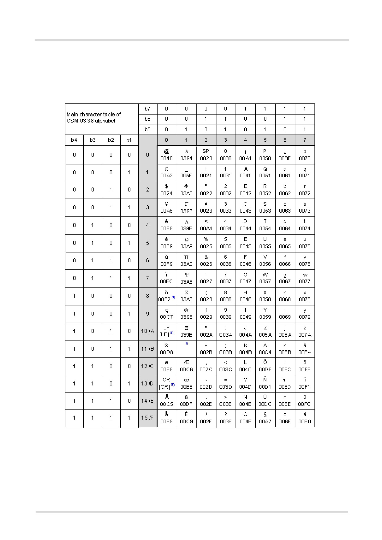
1.6.1
GSM alphabet tables and UCS2 character values
This section provides tables for the GSM 03.38 alphabet supported by the ME. Below any GSM character find
the corresponding two byte character value of the UCS2 alphabet.
(For related mapping definition see: http://www.unicode.org/Public/MAPPINGS/ETSI/GSM0338.TXT)
Figure 1.1: Main character table of GSM 03.38 alphabet
1) This code is an escape to the following extension of the 7 bit default alphabet table.
2) This code is not a printable character and therefore not defined for the UCS2 alphabet. It shall be treated as the accom-
panying control character.
3) See Section 1.5, Communication between Customer Application and TC65i for further details on using backspace and
"ò" character.
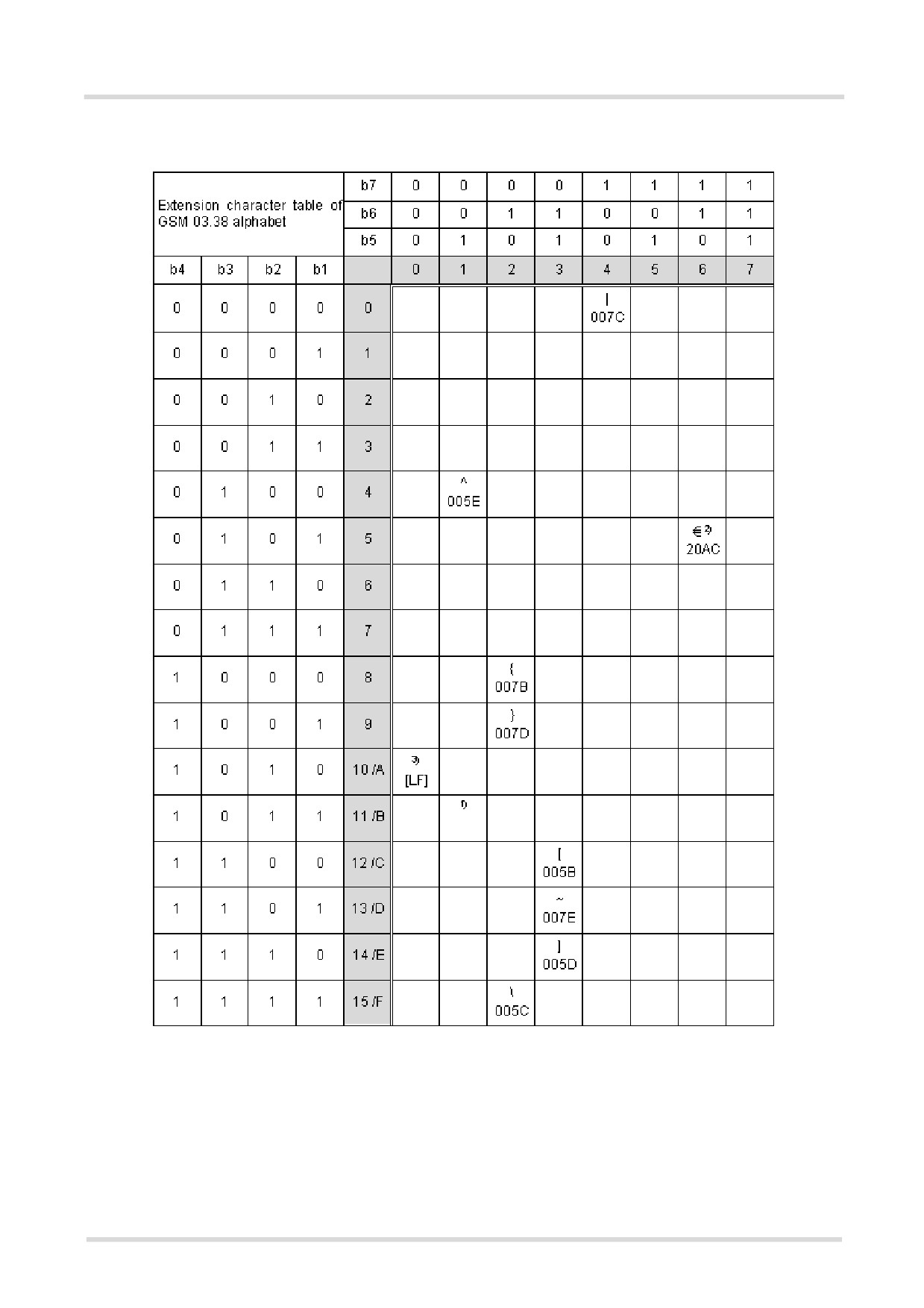
Figure 1.2: Extension character table of GSM 03.38 alphabet
1) This code value is reserved for the extension to another extension table. On receipt of this code, a receiving entity shall
display a space until another extension table is defined.
2) This code represents the EURO currency symbol. The code value is the one used for the character 'e'. Therefore a receiv-
ing entity which is incapable of displaying the EURO currency symbol will display the character 'e' instead.
3) This code is defined as a Page Break character and may be used for example in compressed CBS messages. Any mobile
which does not understand the 7 bit default alphabet table extension mechanism will treat this character as Line Feed.
In the event that an MS receives a code where a symbol is not represented in Figure 1.2, Extension character
table of GSM 03.38 alphabet the MS shall display the character shown in the main default 7 bit alphabet table
(see Figure 1.1, Main character table of GSM 03.38 alphabet).
1.6.2
UCS2 and GSM data coding and conversion for SMS text mode
and Remote SAT
This section provides basic information on how to handle input and output character conversion for SMS text
mode and Remote SAT if internal (TA) and external (TE) character representation differ, i.e. if the Data Coding
Scheme and the TE character use different coding.
1.6.2.1
Implementing output of SIM data to Terminal (direction TA to
TE)
Used character set
DCS = 7 bit
DCS = 8 bit
DCS = 16 bit
GSM
Data
UCS2
GSM
Case 1
Case 2
Case 3
GSM (1:1)
8 bit to IRA (1:2)
UCS2 to IRA (2:4)
UCS2
Case 4
Case 5
Case 6
GSM to IRA (1:4)
8 bit to IRA (1:4)
UCS2 to IRA (2:4)
Note: The ratio of SIM bytes to output bytes is given in parentheses.
Case 1
Every GSM character is sent to the TE as it is (8-bit value with highest bit set to zero).
Example: 47'H, 53'H, 4D'H → 47'H, 53'H, 4D'H, displayed as "GSM"
Case 2
Every data byte is sent to the TE as 2 IRA characters each representing a halfbyte.
Example: B8'H (184 decimal) → 42'H, 38'H, displayed as "B8"
Case 3
Every 16-bit UCS2 value is sent to the TE as 4 IRA characters.
Example: C4xA7'H (50343 decimal) → 43'H, 34'H, 41'H, 37'H, displayed as "C4A7"
Problem: An odd number of bytes leads to an error because there are always two bytes needed for each USC2
character
Case 4
Every GSM character is sent to the TE as 4 IRA characters to show UCS2 in text mode.
Example: 41'H ("A") → 30'H, 30'H, 34'H, 31'H, displayed as "0041"
Case 5
Every data byte is sent to the TE as IRA representation of UCS2 (similar to case 4).
Example: B2'H → 30'H, 30'H, 42'H, 32'H, displayed as "00B2"
Case 6
Every 16-bit value is sent to the TE as IRA representation of it. It is assumed that number of bytes is even.
Example: C3x46'H → 43'H, 33'H, 34'H, 36'H, displayed as "C346"
1.6.2.2
Implementing input of Terminal data to SIM (direction TE to TA)
Used character set
DCS = 7 bit
DCS = 8 bit
DCS = 16 bit
GSM
Data
UCS2
GSM
Case 1
Case 2
Case 3
GSM (1:1)
IRA to 8 bit (2:1)
IRA to 16 bit (4:2)
UCS2
Case 4
Case 5
Case 6
UCS2 to GSM (4:1)
UCS2 to 8 bit (4:1)
UCS2 to 16 bit (4:2)
Note: The ratio between the number of input characters and bytes stored on the SIM is given in parentheses.
Case 1
Every character is sent from TE to TA as GSM character (or ASCII with standard terminal emulation, e.g. Hyper-
terminal).
Character value must be in range from 0 to 127 because of 7-bit GSM alphabet.
To reach maximum SMS text length of 160 characters in 140 bytes space characters will be compressed on SIM.
This must be set using the parameter <dcs> of AT+CSMP (add 64).
Example: "ABCDEFGH" typed is sent and stored uncompressed as → 4142434445464748'H (stored com-
pressed as 41E19058341E91'H)
Case 2
Every data byte is sent as 2 IRA characters.
Maximum text length is 280 IRA characters which will be converted into 140 bytes SMS binary user data
Example: "C8" typed is sent as 43'H, 38'H → stored as C8'H
Case 3
Every 16-bit value is sent as 4 IRA characters.
Maximum text length is 280 IRA characters which will be converted into 70 UCS2 characters (16-bit each)
Number of IRA characters must be a multiple of four because always 4 half bytes are needed for a 16-bit value
Example: "D2C8" typed is sent as 44'H, 32'H, 43'H, 38'H → stored as D2C8'H
Case 4
Every GSM character is sent as 4 IRA characters representing one UCS2 character.
Example: To store text "ABC" using UCS2 character set you have to type "004100420043".
This is sent as 30'H,30'H,34'H,31'H, 30'H,30'H,34'H,32'H, 30'H,30'H,34'H,33'H → detected as IRA representa-
tion of 3 UCS2 characters, converted to GSM character set and stored as 41'H, 42'H, 43'H.
Maximum input is 640 IRA characters repesenting 160 UCS2 characters when compression is active. These are
converted to 160 GSM 7-bit characters.
Without compression only 140 GSM characters can be stored which are put in as 560 IRA characters.
Values of UCS2 characters must be smaller than 80'H (128 decimal) to be valid GSM characters.
Number of IRA characters must be a multiple of four. Problems:
• "41"
→ Error, there are four IRA characters (two bytes) needed
• "0000" → Error, not an UCS2 character
• "4142" → Error, value of UCS2 character > 7F'H
• "008B" → Error, value of UCS2 character > 7F'H
This affects the maximum input length of a string)
Case 5
Every UCS2 character is sent as 4 IRA characters and is converted into two 8-bit values. This means that the
first two characters have to be '00'.
Example: UCS2 character 009F'H typed as "009F" is sent as 30'H,30'H,39'H,46'H → converted into 8-bit value
9F'H.
Maximum number of UCS2 characters is 140 which are represented by 560 IRA characters. Number of IRA char-
acters must be a multiple of four.
Case 6
Every UCS2 character is sent as 4 IRA characters each and is converted into a 16-bit value again.
Example: UCS2 character 9F3A'H typed as "9F3A" is sent as 39'H,46'H,33'H,41'H → converted into 9F3A'H.
Maximum number of UCS2 characters is 70 which are represented by 280 IRA characters. Number of IRA char-
acters must be a multiple of four.
Invalid UCS2 values must be prevented.
1.7
Unsolicited Result Code Presentation
URC stands for Unsolicited Result Code and is a report message issued by the ME without being requested by
the TE, i.e. a URC is issued automatically when a certain event occurs. Hence, a URC is not issued as part of
the response related to an executed AT command.
Typical events leading to URCs are incoming calls ("RING"), waiting calls, received short messages, changes in
temperature, network registration etc.
A list of all URCs can be found in Section 23.7, Summary of Unsolicited Result Codes (URC).
To announce a pending URC transmission the ME will do the following:
• The ME activates its RING line (logic "1") for 1 second, i.e. the RING line changes to the physical "Low" level.
This allows the TE to stay in power saving mode until an ME related event requests service.
If several URCs occur coincidently or in quick succession each URC triggers the RING line independently,
although the line will not be deactivated between each URC. As a result, the RING line may stay low for more
than 1 second.
If an incoming call is answered within less than 1 second (with ATA or if autoanswering is set to ATS0=1) than
the RING line will be deactivated earlier.
The "^SHUTDOWN" URC will not activate the RING line.
• If the AT command interface is busy a "BREAK" will be sent immediately but the URC will not be issued until
the line is free. This may happen if the URC is pending in the following cases:
- During the processing of an AT command (i.e. the time after the TE echoes back the first character "A" of
an AT command just sent by itself until the ME responds with "OK" or "ERROR").
- During a data call.
Please note that AT command settings may be necessary to enable in-band signaling, e.g. refer to AT+CMER
or AT+CNMI.
It is strongly recommended to use the multiplex mode to map logical communication channels onto the serial line
of the TC65i, for details refer to [6] and AT command AT+CMUX. Doing so it is possible to use one channel to still
process URCs while having a data call active on another.
For most of these messages, the ME needs to be configured whether or not to send a URC. Depending on the
AT command, the URC presentation mode can be saved to the user defined profile (see AT&W), or needs to be
activated every time you reboot the ME. Several URCs are not user definable, such as "^SYSSTART",
"^SYSSTART <text>", "^SHUTDOWN"
If autobauding is enabled (AT+IPR=0), URCs generated after restart will be output with 115200 bps until the ME
has detected the current bit rate. The URCs "^SYSSTART", "^SYSSTART <text>", however, are not presented
at all. For details please refer to Section 4.9.1, Autobauding. To avoid problems we recommend to configure a
fixed bit rate rather than using autobauding.
1.8
Errors and Messages
The command result codes "+CME ERROR: <err>" and "+CMS ERROR: <err>" indicate errors related to mobile
equipment or network functionality.
The format of <err> can be either numeric or verbose and is selectable via AT+CMEE.
A result error code terminates the execution of the command and prevents the execution of all remaining com-
mands that may follow on the same command line. If so, neither "ERROR" nor "OK" result codes are returned
for these commands. A 30 seconds timeout will deliver "ERROR" when the input of a command is not complete.
Using the wrong command syntax may result in errors: For example, using the execute command syntax
although the command has no execute format, causes "ERROR" to be returned. Likewise, using the write com-
mand syntax although the command has no write format causes "+CME ERROR: <err>" to be returned.
See also:
• Section 2.12.1, CME/CMS Error Code Overview
• Section 2.5.1, Verbose and numeric result codes
• Section 3.4, AT+CEER
1.9
Auxiliary Serial Interface
The second serial interface (ASC1) is designed as an additional interface for applications which need multiple
parallel access to the TC65i, e.g. to query status information while a data connection is in progress on ASC0.
However, the auxiliary interface provides only limited functionality:
• Multiplex mode via AT+CMUX is not supported.
• DTR, DSR, DCD, RING hardware lines do not exist. AT commands for controlling the behavior of these lines
(AT&D, AT&C, AT&S) can be used but will have no effect.
• CSD calls are not supported.
• Fax calls are not supported.
• When you set up packet switched connections take care that your application uses only AT commands,
parameters and signal lines supported on the ASC1 interface. For example, keep in mind that Microsoft Dial-
up connections are typically trying to request the DCD line status and that common modem drivers use to
send commands such as AT+CBST or ATS7, which may not be supported.
• No Autobauding. The hardware is not capable of automatically detecting the baudrate on this interface, so
the AT command which selects autobauding (AT+IPR=0) is not allowed and returns ERROR.
ASC1 is disabled when the multiplexer is enabled on the first serial interface ASC0. Yet, both ASC1 and the mul-
tiplexer channel 2 are using the same parameters, and thus, the same user defined profile (if any). As a result,
a user profile stored on multiplexer channel 2 takes effect on ASC1 after closing the multiplexer and starting up
ASC1. Likewise, a user profile stored on ASC1 will be loaded on multiplexer channel 2.
This may be a problem when ASC1 is not connected, but flow control (for example AT\Q1 or AT\Q3) is stored to
the user profile on the multiplexer channel 2. In this case, flow control takes effect on ASC1, when the multiplexer
is switched off. If then for example a large amount of URCs is generated, their transmission might be stopped
due to the flow control. To avoid this problem we recommend that you do not activate flow control on multiplexer
channel 2 when you set up a user profile with AT&W.
1.10
Serial Interface Flow Control
Flow control is essential to prevent loss of data or avoid errors when, in a data or fax call, the sending device is
transferring data faster than the receiving side is ready to accept. When the receiving buffer reaches its capacity,
the receiving device should be capable to cause the sending device to pause until it catches up.
There are basically two approaches to regulate data flow: Software flow control and hardware flow control. The
High Watermark (HWM) of the input/output buffer should be set to approximately 60% of the total buffer size, the
Low Watermark (LWM) is recommended to be about 30%. The data flow should be stopped when the buffer
capacity rises close to the High Watermark and resumed when it drops below the Low Watermark. The time
required to cause stop and go results in a hysteresis between the High and Low Watermarks.
1.10.1
Software Flow Control (XON/OFF Handshake)
Software flow control can be used to control the data flow in both directions from DTE to TC65i and from TC65i
to DTE. Software flow control uses different characters to stop (XOFF, decimal 19) and resume (XON, decimal
17) data flow. Hence, all data that represent XON or XOFF characters will be interpreted as control characters.
This applies also to characters included within the data stream to be transmitted (usually plain ASCII text files do
not inlude such characters). The only advantage of software flow control is that three wires would be sufficient
on the serial interface.
1.10.2
Hardware Flow Control (RTS/CTS Handshake)
Hardware flow control sets or resets the RTS/CTS wires. This approach is faster and more reliable, and there-
fore, the better choice. When the HWM is reached, CTS is set inactive. When the LWM is passed, CTS goes
active again. To achieve smooth data flow, ensure that the RTS/CTS lines are present on your application plat-
form.
Configuring hardware flow control
• Hardware flow control must be set on both sides: with AT\Q3 or AT+IFC in the ME and an equivalent RTS/
CTS handshake option in the host application.
• The default setting of the ME is AT\Q0 (no flow control) which must be altered to AT\Q3 (RTS/CTS hardware
handshake on). The setting is stored volatile and must be restored each time after rebooting the ME.
• AT\Q has no read command. To verify the current setting of AT\Q, simply check the settings of the active
profile with AT&V.
• Often, fax programs run an intialization procedure when started up. The intialization commonly includes
enabling RTS/CTS hardware handshake, eliminating the need to set AT\Q3 once again. However, before set-
ting up a CSD call, you are advised to check that RTS/CTS handshake is set.
Buffer design considerations
• Each serial interface (ASC0 and ASC1) of the TC65i uses two buffers, one for the uplink and one for the
downlink. Each buffer has a capacity of minimum 1024 bytes.
• Uplink direction (where ME is receiving data from host application):
CTS control is based on the filling level of the ME's receive buffer. When the application detects that CTS is
being deactivated it must instantly stop sending data to the ME's receive buffer. But still, after deactivation of
CTS, the receive buffer of the ME can accept another 512 bytes.
• Downlink direction (where ME is sending data to host application):
The transmit buffer of the ME can hold at least 1024 bytes. After deactivation of RTS the ME sends max. 2
more bytes and then stops transferring data to the application.
The maximum time RTS can be kept inactive without losing data is determined by the buffer size and the max-
imum possible over-the-air data rate. In any case, the local data rate between DCE and DTE (AT+IPR) should
be set to a value higher than the maximum possible over-the-air data rate.
• Buffer size recommended for the host application:
Just like the ME, the host application should include send and receive buffers for each serial interface. To
handle large amounts of data at high speed a buffer capacity of 1024 bytes is recommended. If the host appli-
cation is designed mainly for one direction (uplink or downlink) a lower buffer size will do for the direction
where less data is transferred.
In fact, the optimal size of the host application buffers is a matter of finding the balance between the amount
of data, data throughput, reaction time of the application when handling the buffer, processor performance
and available memory. To give an example, a small buffer size (such as 256 bytes) increases the frequency
of deactivating RTS/CTS and the frequency of flushing the buffer, thus diminishing the efficiency of the appli-
cation.
Also, please consider that RTS/CTS flow control cannot stop the data stream coming from the network, e.g.
in a GPRS or fax connection. So the lack of appropriate hardware flow control increases the risk of losing data
packets if, like in the case of UDP, the connection protocol has no or only minimum error handling functions.
Other network protocols are using high level flow control mechanisms. For example, to prevent loss of data
the TCP protocol uses retransmission algorithms, fax applications usually repeat the transfer of faulty pages.
1.11
Common PCN Handset Specification (CPHS)
The ME provides features to implement a device following the prerequisites of the Common PCN Handset Spec-
ification (CPHS) Phase 2.
CPHS Feature
Description/Remarks
AT command
Alternate Line Service
Using two phone numbers with one SIM card.
AT^SALS
Voice Message Waiting
Indicate the receipt of a short message coded as Voice Mes-
AT^SIND,
Indication
sage Waiting Indicator as defined by the CPHS Phase 2
AT+CMER, indicators
standard.
"vmwait1" and
"vmwait2"
Operator (Service pro-
Read specific Elementary Files (6F14h, 6F18h) from SIM.
AT+CRSM
vider) name from SIM
Network and Service Pro-
Lock/Unlock an ME to specific HPLMN and service provider.
AT+CLCK,
vider Lock
(AT+CPIN)
Call Forwarding
Get and set diverted call status. Access specific Elementary
AT+CCFC, AT+CRSM
File (6F13h) from SIM.
Customer Service Profile
Setting services and their menu entries depending on cus-
AT+CRSM
(CSP)
tomer profiles.
Information numbers
Hierarchically structured service numbers phonebook on
AT+CRSM
SIM according to CPHS 4.2 (mandatory).
2.
Configuration Commands
The AT Commands described in this chapter allow the external application to determine the TC65i's behaviour
under various conditions.
2.1
AT&F Set all current parameters to manufacturer defaults
AT&F sets all current parameters to the manufacturer defined profile. All defined GPRS contexts which are not
activated or not online will be undefined if the non volatile storage of CGDCONT settings is not activated by the
AT^SCFG parameter "GPRS/PersistentContexts" (see AT+CGDCONT).
Syntax
Exec Command
AT&F[<value>]
Response(s)
OK
PIN ASC0 ASC1
USB MUX1 MUX2 MUX3 Charge
4
Last
Reference(s)
-
+
+
+
+
+
+
-
+
-
V.250
Parameter Description
<value>(num)
[0]
Set all TA parameters to manufacturer defaults
Notes
• List of parameters reset to manufacturer default can be found in Section 23.6, Factory Default Set-
tings Restorable with AT&F.
• In addition to the default profile, you can store an individual one with AT&W. To alternate between the two pro-
files enter either ATZ (loads user profile) or AT&F (restores factory profile).
• Every ongoing or incoming call will be terminated.
2.2
AT&V Display current configuration
AT&V returns the current parameter setting. The configuration varies depending on whether or not PIN authen-
tication has been done and whether or not Multiplex mode is enabled (see AT+CMUX).
Syntax
Exec Command
AT&V[<value>]
Response(s)
ACTIVE PROFILE:
... (see Section 2.2.1, AT&V responses)
OK
PIN ASC0 ASC1
USB MUX1 MUX2 MUX3 Charge
4
Last
Reference(s)
-
+
±
+
+
±
±
-
+
-
V.250
Parameter Description
<value>(num)
[0]
Profile number
Notes
• The value of \Q (flow control) is also determined by the AT+IFC command. In case the value set by AT+IFC
cannot be represented by a \Q equivalent, \Q255 will be displayed.
• The parameters of AT^SMGO can only be displayed after the SMS data from the SIM have been read success-
fully for the first time. Reading starts after successful SIM authentication has been performed, and may take
up to 30 seconds depending on the SIM used. While the read process is in progress, an attempt to read the
parameter will result in empty values.
• The parameter of AT+CSDH will only be displayed in SMS PDU mode, see AT+CMGF.
2.2.1
AT&V responses
The following tables show four different kinds of responses depending on whether or not the PIN is entered and
whether or not the Multiplex mode is enabled (see AT+CMUX).
Table 2.1: Current configuration on ASC0 / MUX channel 1 / USB (example)
PIN authentication done
No PIN authentication
ACTIVE PROFILE:
ACTIVE PROFILE:
E1 Q0 V1 X4 &C1 &D2 &S0 \Q0 \V1
E1 Q0 V1 X4 &C1 &D2 &S0 \Q0 \V1
S0:000 S3:013 S4:010 S5:008 S6:000 S7:060 S8:000
S0:000 S3:013 S4:010 S5:008 S6:000 S7:060 S8:000
S10:002 S18:000
S10:002 S18:000
+CBST: 7,0,1
+CBST: 7,0,1
+CRLP: 61,61,78,6
+CRLP: 61,61,78,6
+CR: 0
+CR: 0
+FCLASS: 0
+FCLASS: 0
+CRC: 0
+ICF: 3
+CMGF: 1
+IFC: 0,0
+CSDH: 0
+ILRR: 0
+CNMI: 0,0,0,0,1
+IPR: 115200
+ICF: 3
+CMEE: 2
+IFC: 0,0
^SCKS: 0,1
+ILRR: 0
^SSET: 0
+IPR: 115200
OK
+CMEE: 2
^SMGO: 0,0
+CSMS: 0,1,1,1
^SACM: 0,"000000","000000"
^SLCC: 0
^SCKS: 0,1
^SSET: 0
+CREG: 0,1
+CLIP: 0,2
+CAOC: 0
+COPS: 0,0,"operator"
+CGSMS: 3
OK
Table 2.2: Current configuration on ASC1 and MUX channels 2 and 3 (example)
PIN authentication done
No PIN authentication
ACTIVE PROFILE:
ACTIVE PROFILE:
E1 Q0 V1 X4 &C1 &D0 &S0 \Q0 \V1
E1 Q0 V1 X4 &C1 &D0 &S0 \Q0 \V1
S0:000 S3:013 S4:010 S5:008
S0:000 S3:013 S4:010 S5:008
+CR: 0
+CR: 0
+CRC: 0
+ICF: 3
+CMGF: 1
+IFC: 0,0
+CSDH: 0
+ILRR: 0
+CNMI: 0,0,0,0,1
+IPR: 115200
+ICF: 3
+CMEE: 2
+IFC: 0,0
^SCKS: 0,1
+ILRR: 0
^SSET: 0
+IPR: 115200
+CGSMS: 3
+CMEE: 2
OK
^SMGO: 0,0
+CSMS: 0,1,1,1
^SACM: 0,"000000","000000"
^SLCC: 0
^SCKS: 0,1
^SSET: 0
+CREG: 0,1
+CLIP: 0,2
+CAOC: 0
+COPS: 0,0,"operator"
+CGSMS: 3
OK
2.3
AT&W Stores current configuration to user defined profile
AT&W stores the currently set parameters to a user defined profile in the non-volatile memory.
Syntax
Exec Command
AT&W[<value>]
Response(s)
OK
ERROR
+CME ERROR: <err>
PIN ASC0 ASC1
USB MUX1 MUX2 MUX3 Charge
4
Last
Reference(s)
-
+
+
+
+
+
+
-
+
-
V.250
Parameter Description
<value>(num)
[0]
Number of profile
Notes
• The user defined profile will be restored automatically after power-up. Use ATZ to restore user profile and
AT&F to restore factory settings. Until the first use of AT&W, ATZ works as AT&F.
• AT&W stores all global settings and the current local settings of the interface, on which the command is exe-
cuted.
• A list of parameters stored to the user profile can be found in Section 23.5, AT Command Settings stor-
able with AT&W.
2.4
ATQ Result code presentation mode
This command determines whether or not the TA transmits any result code to the TE. Other information text
transmitted as response is not affected.
Syntax
Exec Command
ATQ[<n>]
Response(s)
If <n>=0:
OK
If <n>=1:
(none)
PIN ASC0 ASC1
USB MUX1 MUX2 MUX3 Charge
4
Last
Reference(s)
-
+
+
+
+
+
+
-
+
-
V.250
Parameter Description
<n>(num)(&W)(&V)
[0](&F)
DCE transmits result code
1
Result codes are suppressed and not transmitted
2.5
ATV Result code format mode
This command determines the contents of header and trailer transmitted with AT command result codes and
information responses. Possible responses are described in Section 2.5.1, Verbose and numeric result codes.
Syntax
Exec Command
ATV[<value>]
Response(s)
OK
ERROR
PIN ASC0 ASC1
USB MUX1 MUX2 MUX3 Charge
4
Last
Reference(s)
-
+
+
+
+
+
+
-
+
-
V.250
Parameter Description
<value>(num)(&W)(&V)
[0]
Information response: <text><CR><LF>
Short result code format: <numeric code><CR>
1(&F)
Information response: <CR><LF><text><CR><LF>
Long result code format: <CR><LF><verbose code><CR>
2.5.1
Verbose and numeric result codes
Verbose format
Numeric format
Meaning
OK
0
command executed, no errors
CONNECT
1
link established
RING
2
ring detected
NO CARRIER
3
link not established or disconnected
ERROR
4
invalid command or command line too long
NO DIALTONE
6
no dial tone, dialling impossible, wrong mode
BUSY
7
remote station busy
CONNECT 2400/RLP
47
link with 2400 bps and Radio Link Protocol
CONNECT 4800/RLP
48
link with 4800 bps and Radio Link Protocol
CONNECT 9600/RLP
49
link with 9600 bps and Radio Link Protocol
CONNECT 14400/RLP
50
link with 14400 bps and Radio Link Protocol
ALERTING
alerting at called phone
DIALING
mobile phone is dialing
2.6
ATX Set CONNECT result code format and call monitoring
ATX determines whether or not the TA detects the presence of dial tone and busy signal and whether or not TA
transmits particular result codes.
Syntax
Exec Command
ATX[<value>]
Response(s)
OK
ERROR
PIN ASC0 ASC1
USB MUX1
MUX2 MUX3 Charge
4
Last
Reference(s)
-
+
+
+
+
+
+
-
+
-
V.250
Parameter Description
<value>(num)(&W)(&V)
[0]
CONNECT result code only returned, dial tone and busy detection are both dis-
abled.
1
CONNECT <text> result code only returned, dial tone and busy detection are
both disabled.
2
CONNECT <text> result code returned, dial tone detection is enabled, busy
detection is disabled.
3
CONNECT <text> result code returned, dial tone detection is disabled, busy
detection is enabled.
4(&F)
CONNECT <text> result code returned, dial tone and busy detection are both
enabled.
2.7
AT\V Set CONNECT result code format
Syntax
Exec Command
AT\V[<value>]
Response(s)
OK
ERROR
PIN ASC0 ASC1
USB MUX1 MUX2 MUX3 Charge
4
Last
Reference(s)
-
+
-
+
+
-
-
-
+
-
V.250
Parameter Description
<value>(num)(&W)(&V)
[0]
CONNECT <text> result code returned without RLP trailer
1(&F)
CONNECT <text> result code returned with RLP trailer
Notes
• For circuit switched data calls only.
• Output only if ATX parameter is set with value > 0.
2.8
ATZ Set all current parameters to user defined profile
ATZ sets all current parameters to the user profile stored with AT&W. If a connection is in progress, it will be ter-
minated.
All defined GPRS contexts which are not activated or not online will be undefined if the non volatile storage of
CGDCONT settings is not activated by the AT^SCFG parameter "GPRS/PersistentContexts" (see AT+CGDCONT).
The user defined profile is stored to the non-volatile memory.
Syntax
Exec Command
ATZ[<value>]
Response(s)
OK
PIN ASC0 ASC1
USB MUX1 MUX2 MUX3 Charge
4
Last
Reference(s)
-
+
+
+
+
+
+
-
+
-
V.250
Parameter Description
<value>(num)
[0]
Reset to user profile
Notes
• First the profile will be set to factory default (see AT&F). If there is a valid user profile (stored with AT&W), this
profile will be loaded afterwards.
• Any additional commands on the same command line may be ignored. A delay of 300 ms is required before
next command is sent, otherwise "OK" response may be corrupted.
2.9
AT+CFUN Set phone functionality
The AT+CFUN command serves to control the functionality level of the ME. It can be used to reset the ME, to
choose one of the SLEEP modes or to return to full functionality.
Intended for power saving, SLEEP mode reduces the functionality of the ME to a minimum and thus minimizes
the current consumption. Further information, particularly power supply ratings during the various operating
modes and the timing of hardware signals in SLEEP mode can be found in the "TC65i Hardware Interface
Description, Version 01.100".
SLEEP mode falls in two categories:
• NON-CYCLIC SLEEP mode <fun>=0
• and CYCLIC SLEEP modes, selectable as <fun>= 7 or 9.
NON-CYCLIC SLEEP mode permanently blocks the serial interface. The benefit of the CYCLIC SLEEP mode is
that the serial interface remains accessible and that, in intermittent wake-up periods, characters can be sent or
received without terminating the selected mode. This allows the ME to wake up for the duration of an event and,
afterwards, to resume power saving. Please refer to Section 2.9.1, Wake up the ME from SLEEP mode for a
summary of all SLEEP modes and the different ways of waking up the module.
For CYCLIC SLEEP mode both the ME and the application must be configured to use hardware flow control.
This is necessary since the CTS signal is set/reset every 0.9-2.7 seconds in order to indicate to the application
when the UART is active. The default setting of hardware flow control is AT\Q0 which must be altered to AT\Q3.
For use after restart you are advised to add it to the user profile saved with AT&W.
If both interfaces ASC0 and ASC1 are connected, hardware flow control must be set in either application. See
notes below for further detail.
SLEEP mode management if Java is started: The Java Virtual Machine remains active, but also enters the
SLEEP mode. AT commands can be sent from the Java application to the serial interface, no matter which
SLEEP mode was selected. This allows you to control the ME even if it is in NON-CYCLIC SLEEP mode.
The AT+CFUN test command returns the values of the supported parameters.
The AT+CFUN read command returns the current functionality value.
The AT+CFUN write command can be used to reset the ME, to choose one of the SLEEP modes or to return to
full functionality.
Syntax
Test Command
AT+CFUN=?
Response(s)
+CFUN: (list of supported <fun>s) , (list of supported <rst>s)
OK
Read Command
AT+CFUN?
Response(s)
+CFUN: <fun>
OK
Write Command
AT+CFUN=[<fun>[, <rst>]]
Response(s)
OK
ERROR
+CME ERROR: <err>
PIN ASC0 ASC1
USB MUX1 MUX2 MUX3 Charge
4
Last
Reference(s)
-
+
+
+
±
±
±
-
+
-
GSM 07.07
Unsolicited Result Codes
URC 1
^SYSSTART
Indicates that the ME has been started and is ready to operate. If autobauding is active (AT+IPR=0) the URC
is not generated.
If the ME is configured to enter the Airplane mode after restart or reset the following URC is received on boot-
up: "^SYSSTART AIRPLANE MODE". In this mode, only the AT commands listed in Section 23.4, Avail-
ability of AT Commands Depending on Operating Mode of ME can be used. For details please
refer to the AT^SCFG command, parameter <mapos>.
URC 2
^SYSSTART CHARGE ONLY MODE
Indicates that the ME has entered the CHARGE ONLY mode. This occurs if the charger is connected while
the ME is in POWER DOWN mode. If autobauding is active (AT+IPR=0) the URC is not generated. In
CHARGE ONLY mode the ME is neither registered to the GSM network nor are the serial interfaces fully
accessible. Only the AT commands listed in Section 23.4, Availability of AT Commands Depending
on Operating Mode of ME can be used. For further details on charging refer to the Hardware Interface
Description [2].
Parameter Description
<fun>(num)
0
NON-CYCLIC SLEEP mode:
In this mode, the AT interface is not accessible. Consequently, after setting
<fun>=0, do not send further characters. Otherwise these characters remain
in the input buffer and may delay the output of an unsolicited result code.
The first wake-up event stops power saving and takes the ME back to full func-
tionality level <fun>=1.
[1](&F)(P)
Full functionality (no power saving).
If the ME is in one of the CYCLIC SLEEP modes you can issue AT+CFUN=1
to stop power saving and return to full functionality. If the ME is NON-CYCLIC
SLEEP mode, <fun>=1 can also be sent by the Java application.
Keep in mind that, unlike the reset command described below, this action does
not restart the ME but only changes the level of functionality. See parameter
<rst> for details on the reset.
7
CYCLIC SLEEP mode:
In this mode, the serial interface is shortly enabled while CTS is active. If char-
acters are recognized on the serial interface, the ME stays active for 2 seconds
after the last character was sent or received.
The ME exits SLEEP mode only, if AT+CFUN=1 is entered.
9
CYCLIC SLEEP mode:
In this mode, the serial interface is shortly enabled while CTS is active. If char-
acters are recognized on the serial interface, the ME stays active after the last
character was sent or received for at least the time, which can be configured
by AT^SCFG="PowerSaver/Mode9/Timeout",<psm9to> (temporary wakeup).
In contrast to SLEEP mode 7 assertion of RTS can also be used to temporarily
wake up the ME. In this case too, activity time is at least the time set with
AT^SCFG="PowerSaver/Mode9/Timeout",<psm9to>. RTS can be activated
either from ASC0 or ASC1.
The ME exits SLEEP mode only, if AT+CFUN=1 is entered.
<rst>(num)
The parameter can only be used if the serial interface is enabled.
Due to the command syntax, you need to enter parameter <fun>, followed by <rst>, where <fun> is only a
placeholder and has no effect. See examples below.
[0]
Placeholder for <fun> as stated above.
1
ME resets and restarts to full functionality. After reset and restart, PIN 1
authentication is necessary (AT+CPIN). If autobauding is enabled, it is recom-
mended to wait 3 to 5 seconds before entering the first AT command. For
details on autobauding refer to Section 4.9.1, Autobauding.
Notes
•
The settings made with AT+CFUN apply to both serial interfaces ASC0 and ASC1.
•
CYCLIC SLEEP mode cannot be activated or resumed as long as data are buffered in one of the output buff-
ers of the ME (ASC0 or ASC1). This should be taken into account, because RTS may be unintentionally
asserted if, for example, one of the following scenarios occurs:
a) Hardware flow control is set in the ME (AT\Q3), but not in the host application (RTS/CTS handshake).
b) The two serial interfaces ASC0 and ASC1 are connected, but one of them is released, e.g. after closing or
deactivating the application connected to this interface.
In cases a) and b) data sent by the ME, such as URCs or outstanding AT command responses, will be buff-
ered in the output buffer of this interface, signalized by the active RTS line until the buffer is emptied.
Therefore, for CYCLIC SLEEP mode to work properly take care that the following requirements be met: Be
sure that data sent by the ME are collected on both interfaces. Activate hardware flow control on ME (TA) and
application side (TE). Avoid releasing one of the interfaces if any URCs are likely to occur on this interface.
•
CYCLIC SLEEP mode cannot be activated or resumed as long as data is buffered in one of the output buffers
of the ME (ASC0 or ASC1). Therefore, ensure that the following requirements be met:
a) If hardware flow control is set in the ME (AT\Q3), the host must also use hardware flow control.
b) Remember that AT\Q3 takes effect only on the interface where the command was set. Therefore, if both
interfaces ASC0 and ASC1 are connected ensure to set AT\Q3 on each interface. However, if only one inter-
face shall be operated ensure that, on the unused interface, AT\Q3 is neither enabled and nor stored to the
AT&W user profile. This is necessary to avoid that URCs, outstanding AT command responses or, after restart
even the "^SYSSTART" URC might be buffered on the unused interface without being collected by the host
application.
•
In Multiplex mode, the CFUN profile is shared by all multiplexer channels.
•
If the ME is in Multiplexer mode, it is not recommended to activate SLEEP mode with AT+CFUN=<fun>. The
best approach to properly control SLEEP mode in this case is to issue the PSC messages described in [6],
Section "Power saving control".
•
If the host application uses the USB interface, power saving must be configured both on the TC65i module
and on the USB host, i.e. the USB host must be set to Suspend mode (usually Selective or Global Suspend).
Otherwise, if you change only the AT+CFUN parameters, the selected <fun> level will be accepted but the
active USB keeps the module alive and thus prevents power saving until the USB plug is disconnected. Vice
versa, if the module is in SLEEP mode restarting the USB will cause the module to stop power saving
although the selected CFUN level does not change.
•
When a circuit-switched call is in progress, <fun>=7 or 9 can be activated without terminating the call. How-
ever, setting <fun>=0 during a circuit-switched call immediately disconnects this call.
•
To check whether power saving is on, you can query the status with the read command AT+CFUN? only if
the module is in full functionality mode or in CYCLIC SLEEP mode. If available, you can also take advantage
of the status LED controlled by the SYNC pin (see AT^SSYNC and [2]). With AT^SSYNC you can select differ-
ent modes of LED signalization during SLEEP modes (see Section 19.6.1, ME status indicated by status LED
patterns for details). However, the module can wake up temporarily from power saving without leaving its
CYCLIC SLEEP mode (without changing +CFUN "<fun>"), e.g. for a network scan after a loss of radio cov-
erage, or after receipt of serial data during CYCLIC SLEEP mode. During this "temporary wakeup state" the
LED will operate as if the ME was in full functionality mode.
•
Recommendation: In NON-CYCLIC SLEEP mode, you can set an RTC alarm to wake up the ME and return
to full functionality. This is a useful approach because, in this mode, the AT interface is not accessible.
2.9.1
Wake up the ME from SLEEP mode
A wake-up event is any event that causes the ME to draw more current. Depending on the selected mode, the
wake-up event either switches the SLEEP mode off and takes the ME back to full functionality AT+CFUN=1, or
activates the ME temporarily without terminating the selected SLEEP mode.
Definitions of the state transitions described in Table 2.3:
• Quit: ME exits SLEEP mode.
• Temporary: ME becomes active temporarily for the duration of the event and the mode-specific follow-up time
after the last character was sent or received on the serial interface.
• No effect: Event is not relevant in the selected SLEEP mode. The ME does not wake up.
Table 2.3: Wake-up events in NON-CYCLIC and CYCLIC SLEEP modes
Event
Selected mode:
Selected mode:
<fun>=0
<fun>=7 or 9
Ignition line
No effect
No effect
RTS0 or RTS1 activation
Quit
Mode 7: No effect (RTS is only
used for flow control)
Mode 9: Temporary
Unsolicited Result Code (URC)
Quit
Temporary
Incoming voice or data call
Quit
Temporary
Any AT command (incl. outgoing
Not possible (UART disabled)
Temporary
SMS, voice or data call)
Incoming SMS (AT+CNMI is set to
No effect
No effect
0,0 (this is the default setting)
Incoming SMS (AT+CNMI is set to
Quit
Temporary
1,1)
GPRS data transfer
Not possible (UART disabled)
Temporary
RTC alarm (AT+CALA)
Quit
Temporary
AT+CFUN=1
Not possible (UART disabled)
Quit
In case of Java, the following events will cause the ME to quit NON-CYCLIC SLEEP mode <fun>=0:
- Toggling the RTS line
- Sending data on the serial interface
- Voice or data call (incoming and outgoing)
- AT+CFUN=1
- Terminating Java
2.10
AT^SMSO Switch off mobile station
AT^SMSO initiates the power-off procedure. High level of the module's PWR_IND pin and the URC "^SHUT-
DOWN" notify that the procedure has completed and the module has entered the POWER DOWN mode. There-
fore, be sure not to disconnect the operating voltage until PWR_IND is high or until the URC "^SHUTDOWN" is
displayed. Otherwise, you run the risk of losing data. For further details on how to turn off the module see the [2].
Syntax
Test Command
AT^SMSO=?
Response(s)
OK
Exec Command
AT^SMSO
Response(s)
^SMSO: MS OFF
OK
ERROR
PIN ASC0 ASC1
USB MUX1 MUX2 MUX3 Charge
4
Last
-
+
+
+
+
+
+
-
+
+
Unsolicited Result Code
^SHUTDOWN
Indicates that the power-off procedure is finished and the module will be switched off in less than 1 second.
Notes
• Do not send any other AT command after AT^SMSO.
• If AT^SMSO is entered on one of the Multiplexer channels the ME closes the Multiplexer channels, terminates
the Multiplexer and deactivates all other functions. Then, the URC "^SHUTDOWN" will be issued on the phys-
ical serial interface (ASC0). The URC will be transmitted at the bit rate last activated on ASC0 for use with
the Multiplex driver.
• If both interfaces ASC0 and ASC1 are connected the URC appears on both of them.
• If the module is in NORMAL mode and the charger is connected to the VCHARGE line, the AT^SMSO com-
mand causes the module to shut down shortly and then start into the CHARGE ONLY mode. If the module is
in CHARGE ONLY mode the AT^SMSO command is not supported at all. In both cases, the module can only
be switched off by disconnecting the charger. See also [2].
2.11
AT+GCAP Request complete TA capabilities list
AT+GCAP returns a list of additional capabilities.
Syntax
Test Command
AT+GCAP=?
Response(s)
OK
Exec Command
AT+GCAP
Response(s)
+GCAP: <name>
OK
PIN ASC0 ASC1
USB MUX1 MUX2 MUX3 Charge
4
Last
Reference(s)
-
+
+
+
+
+
+
-
+
-
V.250
Parameter Description
<name>(str)
e.g.: +CGSM,+FCLASS
Note
•
+CGSM: The response text shows which GSM commands of the ETSI standard are supported.
2.12
AT+CMEE Mobile Equipment Error Message Format
AT+CMEE controls the format of the error result codes that indicates errors related to TC65i functionality. Format
can be selected between plain "ERROR" output, error numbers or verbose "+CME ERROR: <err>" and "+CMS
ERROR: <err>" messages.
Possible error result codes are listed in Table 2.4, General "CME ERROR" Codes (GSM 07.07)Table 2.5, Gen-
eral "CME ERROR" Codes (proprietary)Table 2.6, GPRS related "CME ERROR" Codes (GSM 07.07)Table 2.9,
Java related "CME ERROR" Codes (proprietary) and Table 2.8, SMS related "CMS ERROR" Codes (GSM
07.05).
In multiplex mode (refer AT+CMUX) the setting applies only to the logical channel where selected. The setting on
the other channels may differ.
Syntax
Test Command
AT+CMEE=?
Response(s)
+CMEE: (list of supported<errMode>s)
OK
Read Command
AT+CMEE?
Response(s)
+CMEE: <errMode>
OK
Write Command
AT+CMEE=<errMode>
Response(s)
OK
ERROR
+CME ERROR: <err>
PIN ASC0 ASC1
USB MUX1
MUX2 MUX3
Charge
4
Last
Reference(s)
-
+
+
+
+
+
+
-
+
-
GSM 07.07
Parameter Description
<errMode>(num)(&W)(&V)
0(&F)(D)
Disable result code, i.e. only "ERROR" will be displayed.
1
Enable error result code with numeric values.
2
Enable error result code with verbose (string) values.
Example
To obtain enhanced error messages it is recommended to choose <errMode>=2.
AT+CMEE=2
OK
2.12.1
CME/CMS Error Code Overview
Table 2.4: General "CME ERROR" Codes (GSM 07.07)
<err> Code
Text (if AT+CMEE=2)
0
phone failure
1
no connection to phone
2
phone adapter link reserved
3
operation not allowed
4
operation not supported
5
PH-SIM PIN required
6
PH-FSIM PIN required
7
PH-FSIM PUK required
10
SIM not inserted
11
SIM PIN required
12
SIM PUK required
13
SIM failure
14
SIM busy
15
SIM wrong
16
incorrect password
17
SIM PIN2 required
18
SIM PUK2 required
20
memory full
21
invalid index
22
not found
23
memory failure
24
text string too long
25
invalid characters in text string
26
dial string too long
27
invalid characters in dial string
30
no network service
31
network timeout
32
network not allowed - emergency calls only
40
network personalization PIN required
41
network personalization PUK required
42
network subset personalization PIN required
43
network subset personalization PUK required
44
service provider personalization PIN required
45
service provider personalization PUK required
46
corporate personalization PIN required
47
corporate personalization PUK required
48
PH-SIM PUK (master phone code) required
100
unknown
132
service option not supported
<err> Code
Text (if AT+CMEE=2)
133
requested service option not subscribed
134
service option temporary out of order
256
operation temporary not allowed
257
call barred
258
phone busy
259
user abort
260
invalid dial string
261
SS not executed
262
SIM blocked
263
invalid block
Table 2.5: General "CME ERROR" Codes (proprietary)
<err> Code
Text (if AT+CMEE=2)
673
audio manager not ready
674
audio format cannot be configured
705
SIM toolkit menu has not been configured
706
SIM toolkit already in use
707
SIM toolkit not enabled
737
+CSCS type not supported
738
+CSCS type not found
741
must include <format> with <oper>
742
incorrect <oper> format
743
<oper> length too long
744
SIM full
745
unable to change PLMN list
746
network operator not recognised
749
invalid command length
750
invalid input string
753
missing required cmd parameter
754
invalid SIM command
755
invalid file Id
756
missing required P1/2/3 parameter
757
invalid P1/2/3 parameter
758
missing required command data
759
invalid characters in command data
761
CTM call is not setup
764
missing input value
765
invalid input value
766
unsupported value or mode
767
operation failed
768
multiplexer already active
769
unable to get control of required module
<err> Code
Text (if AT+CMEE=2)
770
SIM invalid - network reject
771
call setup in progress
772
SIM powered down
773
SIM file not present
Table 2.6: GPRS related "CME ERROR" Codes (GSM 07.07)
<err> Code
Text (if AT+CMEE=2)
103
illegal MS
106
illegal ME
107
GPRS services not allowed
111
PLMN not allowed
112
location area not allowed
113
roaming not allowed in this location area
148
unspecified GPRS error
149
PDP authentication failure
150
invalid mobile class
Table 2.7: GPRS related "CME ERROR" Codes (proprietary)
<err> Code
Text (if AT+CMEE=2)
577
GPRS - activation rejected by GGSN
578
GPRS - unspecified activation rejection
579
GPRS - bad code or protocol rejection
580
GPRS - can't modify address
581
GPRS - no echo replyGPRS - CHAP close
582
GPRS - profile (CID) currently unavailable
583
GPRS - a profile (CID) is currently active
584
GPRS - combined services not allowed
585
GPRS - conditional IE error
586
GPRS - context activation rejected
587
GPRS - duplicate TI received
588
GPRS - feature not supported
589
GPRS - service not available
590
GPRS - unknown IE from network
591
GPRS - implicitly detached
592
GPRS - insufficient resources
593
GPRS - invalid activation state (0-1)
594
GPRS - invalid address length
595
GPRS - invalid character in address string
596
GPRS - invalid CID value
597
GPRS - invalid dialstring length
598
GPRS - mode value not in range
599
GPRS - invalid MAND information
<err> Code
Text (if AT+CMEE=2)
600
GPRS - SMS service preference out of range
601
GPRS - invalid TI value
602
GPRS - IPCP negotiation timeout
603
GPRS - LCP negotiation timeout
604
GPRS - LLC error
605
GPRS - LLC or SNDCP failure
606
GPRS - lower layer failure
607
GPRS - missing or unknown APN
608
GPRS - mobile not ready
609
GPRS - MS identity not in network
610
GPRS - MSC temporary not reachable
611
GPRS - message incompatible with state
612
GPRS - message type incompatible with state
613
GPRS - unknown message from network
614
GPRS - NCP close
615
GPRS - network failure
616
GPRS - no echo reply
617
GPRS - no free NSAPIs
618
GPRS - processing of multiple CIDs not supported
619
GPRS - no PDP context activated
620
GPRS - normal termination
621
GPRS - NSAPI already used
622
GPRS - address element out of range
623
GPRS - PAP close
624
GPRS - PDP context w/o TFT already activated
625
GPRS - PDP type not supported
626
GPRS - peer refuses our ACCM
627
GPRS - peer refuses our IP address
628
GPRS - peer refuses our MRU
629
GPRS - peer rerequested CHAP
630
GPRS - profile (CID) not defined
631
GPRS - unspecified protocol error
632
GPRS - QOS not accepted
633
GPRS - QOS validation fail
634
GPRS - reactivation required
635
GPRS - regular deactivation
636
GPRS - semantic error in TFT operation
637
GPRS - semantic errors in packet filter
638
GPRS - semantically incorrect message
639
GPRS - service type not yet available
640
GPRS - syntactical error in TFT operation
641
GPRS - syntactical errors in packet filter
<err> Code
Text (if AT+CMEE=2)
642
GPRS - too many RXJs
643
GPRS - unknown PDP address or type
644
GPRS - unknown PDP context
645
GPRS - user authorisation failed
646
GPRS - QOS invalid parameter
647
GPRS - FDN failure
648
GPRS - bad default PDP context parameters
649
GPRS - bad PDP context parameters
650
GPRS - PDP context already active
660
GPRS - no echo reply
661
GPRS - syntactical error in TFT operation
Table 2.8: SMS related "CMS ERROR" Codes (GSM 07.05)
<err> Code
Text (if AT+CMEE=2)
1
unassigned (unallocated) number
8
operator determined barring
10
call barred
21
short message transfer rejected
27
destination out of service
28
unidentified subscriber
29
facility rejected
30
unknown subscriber
38
network out of order
41
temporary failure
42
congestion
47
resources unavailable, unspecified
50
requested facility not subscribed
69
requested facility not implemented
81
invalid short message transfer reference value
95
invalid message, unspecified
96
invalid mandatory information
97
message type non-existent or not implemented
98
message not compatible with short message protocol state
99
information element non-existent or not implemented
111
protocol error, unspecified
127
interworking, unspecified
128
telematic interworking not supported
129
short message type 0 not supported
130
cannot replace short message
143
unspecified TP-PID error
144
data coding scheme (alphabet) not supported
145
message class not supported
<err> Code
Text (if AT+CMEE=2)
159
unspecified TP-DCS error
160
command cannot be actioned
161
command unsupported
175
unspecified TP-command error
176
TPDU not supported
192
SC busy
193
no SC subscription
194
SC system failure
195
invalid SME address
196
destination SME barred
197
SM rejected-duplicate SM
198
TP-VPF not supported
199
TP-VP not supported
208
do SIM SMS storage full
209
no SMS storage capability in SIM
210
error in MS
211
memory capacity exceeded
212
SIM application toolkit busy
213
SIM data download error
255
unspecified error cause
300
ME failure
301
SMS service of ME reserved
302
operation not allowed
303
operation not supported
304
invalid PDU mode parameter
305
invalid text mode parameter
310
SIM not inserted
311
SIM PIN required
312
PH-SIM PIN required
313
SIM failure
314
SIM busy
315
SIM wrong
316
SIM PUK required
317
SIM PIN2 required
318
SIM PUK2 required
320
memory failure
321
invalid memory index
322
memory full
330
SMSC address unknown
331
no network service
332
network timeout
340
no +CNMA acknowledgement expected
<err> Code
Text (if AT+CMEE=2)
500
unknown error
516
invalid length
519
invalid length or character
520
invalid character in text
532
SIM not ready
533
unread records on SIM
534
CB error unknown
535
PS busy
536
couldn't read SMS parameters from SIM
537
SM BL not ready
538
invalid parameter
539
ME temporary not available
548
invalid (non-hex) chars in PDU
549
incorrect PDU length
550
invalid MTI (message type indication)
551
invalid (non-hex) chars in address
552
invalid address (no digits read)
553
incorrect PDU length (UDL)
554
incorrect SCA length
556
invalid first octet (should be 2 or 34)
557
invalid command type
558
SRR bit not set
559
SRR bit set
560
invalid user data header IE
Table 2.9:
Java related "CME ERROR" Codes (proprietary)
<err> Code
Text (if AT+CMEE=2)
800
Java - unspecified error
801
Java - VM failure
802
Java - midlet not found
803
Java - midlet authentication failed
804
Java - midlet invalid descriptor
805
Java - midlet wrong configuration or profile
806
Java - liblet not found
807
Java - liblet authentication failed
808
Java - liblet invalid descriptor
2.13
AT+CSCS Select TE character set
The AT+CSCS write command informs the TA which character set <chset> is used by the TE. This enables the
TA to convert character strings correctly between TE and ME character sets. See also Section 1.6, Supported
character sets.
Note that when the TA-TE interface is set to 8-bit operation and the used TE alphabet is 7-bit, the highest bit will
be set to zero.
Syntax
Test Command
AT+CSCS=?
Response(s)
+CSCS: (list of supported<chset>s)
OK
Read Command
AT+CSCS?
Response(s)
+CSCS: <chset>
OK
Write Command
AT+CSCS=[<chset>]
Response(s)
OK
ERROR
+CME ERROR: <err>
PIN ASC0 ASC1
USB MUX1
MUX2 MUX3
Charge
4
Last
Reference(s)
-
+
+
+
+
+
+
-
+
-
GSM 07.07, GSM
11.11
Parameter Description
<chset>(str)
“GSM“(&F)(P)
GSM default alphabet (GSM 03.38 subclause 6.2.1);
Note: This setting may cause software flow control problems since the codes
used to stop and resume data flow (XOFF = decimal 19, XON = decimal 17)
are interpreted as normal characters.
“UCS2“
16-bit universal multiple-octet coded character set (ISO/IEC10646 [32]); UCS2
character strings are converted to hexadecimal numbers from 0000 to FFFF;
e.g. "004100620063" equals three 16-bit characters with decimal values 65, 98
and 99.
2.14
AT^SCFG Extended Configuration Settings
AT^SCFG can be used to query and configure various settings of the TC65i.
AT^SCFG read command returns a list of all supported parameters and their current values.
AT^SCFG write command queries a configuration parameter (if no value is entered) or sets its value(s).
Input of parameter names is always coded in GSM character set, parameter values are expected to be given as
specified via AT+CSCS.
Syntax
Test Command
AT^SCFG=?
Response(s)
^SCFG: "AutoExec" , (list of supported <AutoExecCmd>), (list of supported <AutoExecType>), (list of
supported <AutoExecIndex>), (list of supported <AutoExecMode>), (max. string length of
<AutoExecATC>), (time range of <AutoExecPeriod>)
^SCFG: "Call/ECC", (list of supported <ecc>s)
^SCFG: "GPRS/ATS0/withAttach", (list of supported <gs0aa>s)
^SCFG: "GPRS/AutoAttach", (list of supported <gaa>s)
^SCFG: "GPRS/PersistentContexts", (list of supported <gpc>s)
^SCFG: "GPRS/RingOnIncomingData", (list of supported <groid>s)
^SCFG: "MEopMode/Airplane", (list of supported <map>s)
^SCFG: "MEopMode/Airplane/OnStart", (list of supported <mapos>s)
^SCFG: "MEShutdown/OnIgnition", (list of supported <msi>s)
^SCFG: "PowerSaver/Mode9/Timeout", (list of supported <psm9to>s)
^SCFG: "Radio/Band", (list of supported <rbp>s), (list of supported <rba>s)
^SCFG: "Radio/CNS", (list of supported <cns>s)
^SCFG: "Radio/OutputPowerReduction", (list of supported <ropr>s)
^SCFG: "Serial/USB/DDD" , (list of supported <deviceDescr>s) , (list of supported <descrIndex>s) ,
(max. string length of <langId>) , (max. string length of <vendorId>) , (max. string length of
<productId>) , (max. string length of <manufacturer>) , (max. string length of <product>) , (max. string
length of <serialNo>)
^SCFG: "Tcp/BufSize", (list of supported <tcpBufSize>)
^SCFG: "Tcp/IRT", (list of supported <tcpIrt>)
^SCFG: "Tcp/MR", (list of supported <tcpMr>)
^SCFG: "Tcp/OT", (list of supported <tcpOt>)
^SCFG: "Tcp/SAck", (list of supported <tcpSack>)
^SCFG: "Tcp/TTcp", (list of supported <tcpTtcp>)
^SCFG: "Tcp/WithURCs", (list of supported <tcpWithUrc>)
^SCFG: "Trace/Syslog/OTAP", (list of supported <otapTracer>)
^SCFG: "URC/CallStatus/CIEV", (list of supported <succ>s)
^SCFG: "URC/CallStatus/SLCC", (list of supported <sucs>s)
^SCFG: "URC/Datamode/Ringline", (list of supported <udri>s)
^SCFG: "URC/Ringline", (list of supported <uri>s)
^SCFG: "URC/Ringline/ActiveTime", (list of supported <urat>s)
^SCFG: "Userware/Autostart/AppName", (max. string lengths of <uaa>)
^SCFG: "Userware/DebugInterface", (<udbgif1>), (<udbgif2>), (<udbgif3>)
^SCFG: "Userware/Mode", (list of supported <umode>), (length of <uurl>), (range of supported
<uport>values)
^SCFG: "Userware/Stdout", (list of supported <if>), (list of supported <intvalue>), (<filename>), (list of
supported <logmode>)
OK
Read Command
AT^SCFG?
Response(s)
^SCFG: "AutoExec" , <AutoExecCmd>, <AutoExecType>, <AutoExecIndex>, <AutoExecMode>,
<AutoExecATC>[, <AutoExecPeriod>, <AutoExecPeriodTimeLeft>]
^SCFG: "Call/ECC", <ecc>
^SCFG: "GPRS/ATS0/withAttach", <gs0aa>
^SCFG: "GPRS/AutoAttach", <gaa>
^SCFG: "GPRS/PersistentContexts", <gpc>
^SCFG: "GPRS/RingOnIncomingData", <groid>
^SCFG: "MEopMode/Airplane", <map>
^SCFG: "MEopMode/Airplane/OnStart", <mapos>
^SCFG: "MEShutdown/OnIgnition", <msi>
^SCFG: "PowerSaver/Mode9/Timeout", <psm9to>
^SCFG: "Radio/Band", <rbc>, <rba>
^SCFG: "Radio/CNS", <cns>
^SCFG: "Radio/OutputPowerReduction", <ropr>
^SCFG: "Serial/USB/DDD" , <deviceDescr>, <descrIndex>, <langId>, <vendorId>, <productId>,
<manufacturer>, <product>, <serialNo>
^SCFG: "Tcp/BufSize", <tcpBufSize>
^SCFG: "Tcp/IRT", <tcpIrt>
^SCFG: "Tcp/MR", <tcpMr>
^SCFG: "Tcp/OT", <tcpOt>
^SCFG: "Tcp/SAck", <tcpSack>
^SCFG: "Tcp/TTcp", <tcpTtcp>
^SCFG: "Tcp/WithURCs", <tcpWithUrc>
^SCFG: "Trace/Syslog/OTAP", <otapTracer>
^SCFG: "URC/CallStatus/CIEV", <succ>
^SCFG: "URC/CallStatus/SLCC", <sucs>
^SCFG: "URC/Datamode/Ringline", <udri>
^SCFG: "URC/Ringline", <uri>
^SCFG: "URC/Ringline/ActiveTime", <urat>
^SCFG: "Userware/Autostart/AppName", <uaa>
^SCFG: "Userware/DebugInterface", <udbgif1>, <udbgif2>, <udbgif3>
^SCFG: "Userware/Mode"
^SCFG: "Userware/Stdout", <if>[, <intvalue>[, <filename>[, <logmode>]]]
OK
Write Command
Automatic AT command execution
AT^SCFG="AutoExec" , <AutoExecCmd>, <AutoExecType>, <AutoExecIndex>[, <AutoExecMode>,
<AutoExecATC>[, <AutoExecPeriod>]]
Response(s)
^SCFG: "AutoExec" , <AutoExecCmd>, <AutoExecType>, <AutoExecIndex>, <AutoExecMode>,
<AutoExecATC>[, <AutoExecPeriod>, <AutoExecPeriodTimeLeft>]
OK
ERROR
+CME ERROR: <err>
Write Command
Query/Configure Emergency numbers for SIM without ECC field
AT^SCFG="Call/ECC"[, <ecc>]
Response(s)
^SCFG: "Call/ECC", <ecc>
OK
Write Command
(Continued)
Query/Configure Emergency numbers for SIM without ECC field
AT^SCFG="Call/ECC"[, <ecc>]
Response(s)
ERROR
+CME ERROR: <err>
Write Command
GPRS ATS0 with automatic attach
AT^SCFG="GPRS/ATS0/withAttach"[, <gs0aa>]
Response(s)
^SCFG: "GPRS/ATS0/withAttach", <gs0aa>
OK
ERROR
+CME ERROR: <err>
Write Command
Automatic GPRS attach
AT^SCFG="GPRS/AutoAttach"[, <gaa>]
Response(s)
^SCFG: "GPRS/AutoAttach", <gaa>
OK
ERROR
+CME ERROR: <err>
Write Command
Persistent GPRS contexts
AT^SCFG="GPRS/PersistentContexts"[, <gpc>]
Response(s)
^SCFG: "GPRS/PersistentContexts", <gpc>
OK
ERROR
+CME ERROR: <err>
Write Command
Ring on incoming GPRS IP data packets
AT^SCFG="GPRS/RingOnIncomingData"[, <groid>]
Response(s)
^SCFG: "GPRS/RingOnIncomingData", <groid>
OK
ERROR
+CME ERROR: <err>
Write Command
Enable/disable Airplane mode during operation
AT^SCFG="MEopMode/Airplane"[, <map>]
Response(s)
^SCFG: "MEopMode/Airplane", <map>
OK
ERROR
+CME ERROR: <err>
Write Command
Airplane mode upon ME restart
AT^SCFG="MEopMode/Airplane/OnStart"[, <mapos>]
Response(s)
^SCFG: "MEopMode/Airplane/OnStart", <mapos>
OK
ERROR
+CME ERROR: <err>
Write Command
Enable/disable shutdown by ignition line
AT^SCFG="MEShutdown/OnIgnition"[, <msi>]
Response(s)
^SCFG: "MEShutdown/OnIgnition", <msi>
OK
ERROR
+CME ERROR: <err>
Write Command
Query/Set timeout value for power saving mode 9
AT^SCFG="PowerSaver/Mode9/Timeout"[, <psm9to>]
Response(s)
^SCFG: "PowerSaver/Mode9/Timeout", <psm9to>
OK
ERROR
+CME ERROR: <err>
Write Command
Radio band selection
AT^SCFG="Radio/Band"[, <rbp>][, <rba>]
Response(s)
^SCFG: "Radio/Band", <rbp>, <rba>
OK
ERROR
+CME ERROR: <err>
Write Command
Query/Enable/Disable Continuous Network Search
AT^SCFG="Radio/CNS"[, <cns>]
Response(s)
^SCFG: "Radio/CNS", <cns>
OK
ERROR
+CME ERROR: <err>
Write Command
Radio output power reduction
AT^SCFG="Radio/OutputPowerReduction"[, <ropr>]
Response(s)
^SCFG: "Radio/OutputPowerReduction", <ropr>
OK
ERROR
+CME ERROR: <err>
Write Command
Configuration of TCP parameter 'BufSize':
AT^SCFG="Tcp/BufSize"[, <tcpBufSize>]
Response(s)
^SCFG: "Tcp/BufSize", <tcpBufSize>
OK
ERROR
+CME ERROR: <err>
Write Command
Configuration of TCP parameter 'InitialRetransmissionTimeout':
AT^SCFG="Tcp/IRT"[, <tcpIrt>]
Response(s)
^SCFG: "Tcp/IRT", <tcpIrt>
OK
ERROR
+CME ERROR: <err>
Write Command
Configuration of TCP parameter 'MaxRetransmissions':
AT^SCFG="Tcp/MR"[, <tcpMr>]
Response(s)
^SCFG: "Tcp/MR", <tcpMr>
OK
ERROR
+CME ERROR: <err>
Write Command
Configuration of TCP parameter 'OverallTimeout':
AT^SCFG="Tcp/OT"[, <tcpOt>]
Response(s)
^SCFG: "Tcp/OT", <tcpOt>
OK
ERROR
+CME ERROR: <err>
Write Command
Configuration of TCP parameter 'Selective Acknowledge':
AT^SCFG="Tcp/SAck"[, <tcpSack>]
Response(s)
^SCFG: "Tcp/SAck", <tcpSack>
OK
ERROR
+CME ERROR: <err>
Write Command
Configuration of Internet Service URCs:
AT^SCFG="Tcp/WithURCs"[, <tcpWithUrc>]
Response(s)
^SCFG: "Tcp/WithURCs", <tcpWithUrc>
OK
ERROR
+CME ERROR: <err>
Write Command
Tracing:
AT^SCFG="Trace/Syslog/OTAP"[, <otapTracer>]
Response(s)
^SCFG: "Trace/Syslog/OTAP", <otapTracer>
SYSLOG ENABLED
ERROR
+CME ERROR: <err>
Write Command
USB Device Descriptor:
AT^SCFG="Serial/USB/DDD" [, <deviceDescr>, [<descrIndex>], [<langId>], <vendorId>,
<productId>, [<manufacturer>], [<product>], [<serialNo>]]
Response(s)
^SCFG: "Serial/USB/DDD" , <deviceDescr>, <descrIndex>, <langId>, <vendorId>, <productId>,
<manufacturer>, <product>, <serialNo>
OK
ERROR
+CME ERROR: <err>
Write Command
Configuration of URC "+CIEV: call" Call Status Indication
AT^SCFG="URC/CallStatus/CIEV"[, <succ>]
Response(s)
^SCFG: "URC/CallStatus/CIEV", <succ>
OK
ERROR
+CME ERROR: <err>
Write Command
Configuration of URC "^SLCC" Call Status Indication
AT^SCFG="URC/CallStatus/SLCC"[, <sucs>]
Response(s)
^SCFG: "URC/CallStatus/SLCC", <sucs>
OK
ERROR
+CME ERROR: <err>
Write Command
URC indication in datamode via Ring line:
AT^SCFG="URC/Datamode/Ringline"[, <udri>]
Response(s)
^SCFG: "URC/Datamode/Ringline", <udri>
OK
ERROR
+CME ERROR: <err>
Write Command
URC indication via Ring line:
AT^SCFG="URC/Ringline"[, <uri>]
Response(s)
^SCFG: "URC/Ringline", <uri>
OK
Write Command
(Continued)
URC indication via Ring line:
AT^SCFG="URC/Ringline"[, <uri>]
Response(s)
ERROR
+CME ERROR: <err>
Write Command
Duration of active RING line for URC indications:
AT^SCFG="URC/Ringline/ActiveTime"[, <urat>]
Response(s)
^SCFG: "URC/Ringline/ActiveTime", <urat>
OK
ERROR
+CME ERROR: <err>
Write Command
Userware autostart status:
AT^SCFG="Userware/Autostart"[, <upwd>, <ua>]
Response(s)
^SCFG: "Userware/Autostart"[, <ua>]
OK
ERROR
+CME ERROR: <err>
Write Command
Userware autostart application:
AT^SCFG="Userware/Autostart/AppName"[, <upwd>, <uaa>]
Response(s)
^SCFG: "Userware/Autostart/AppName"[, <uaa>]
OK
ERROR
+CME ERROR: <err>
Write Command
Userware autostart delay:
AT^SCFG="Userware/Autostart/Delay"[, <upwd>, <uad>]
Response(s)
^SCFG: "Userware/Autostart/Delay"[, <uad>]
OK
ERROR
+CME ERROR: <err>
Write Command
Userware configuration password:
AT^SCFG="Userware/Passwd"[, <upwd>old, <upwd>new, <upwd>new]
Response(s)
^SCFG: "Userware/Passwd"
OK
ERROR
+CME ERROR: <err>
Write Command
Userware debug interface:
AT^SCFG="Userware/DebugInterface"[, <udbgif1>, <udbgif2>[, <udbgif3>]]
Response(s)
^SCFG: "Userware/DebugInterface", <udbgif1>, <udbgif2>, <udbgif3>
OK
ERROR
+CME ERROR: <err>
Write Command
Userware mode:
AT^SCFG="Userware/Mode"[, <umode>, <uurl>, <uport>]
Response(s)
^SCFG: "Userware/Mode", <umode>, <uurl>, <uport>
OK
ERROR
+CME ERROR: <err>
Write Command
Standard output of userware:
AT^SCFG="Userware/Stdout"[, <if>[, <intvalue>][, <filename>][, <logmode>]]
Response(s)
^SCFG: "Stdout" , <if>[, <intvalue>[, <filename>[, <logmode>]]]
OK
ERROR
+CME ERROR: <err>
Write Command
Watchdog configuration and control:
AT^SCFG="Userware/Watchdog"[, <wd>]
Response(s)
^SCFG: "Watchdog", <wd>
OK
ERROR
+CME ERROR: <err>
PIN ASC0 ASC1
USB MUX1 MUX2 MUX3 Charge
4
Last
-
+
+
+
+
+
+
±
±
-
Unsolicited Result Codes
URC 1
^SCFG: "AutoExec", <AutoExecState>, <AutoExecType>, <AutoExecIndex>,
<AutoExecMode>, <AutoExecATC>
If the event specified with <AutoExecType> occurs and the related AT command line is executed this URC
is issued.
URC 2
^SYSSTART AIRPLANE MODE
This URC is issued each time the Airplane mode is activated, no matter whether Airplane mode is set with
parameter <map>="on" or <mapos>="on". The URC notifies the user that only the AT commands supported
in Airplane mode are accessible. After leaving the Airplane mode the URC "^SYSSTART" indicates that the
ME has returned to Normal mode and the full set of AT commands is accessible again.
Parameter Description
<AutoExecCmd>(str)(+CSCS)
AutoExec Command
This parameter serves to switch the Autoexec function on or off.
If it is switched off (<AutoExecCmd>=0), parameters following <AutoExecIndex> are ignored and all settings
at the given index are restored to their default values.
Value will be saved while switching off the TC65i via AT commands (e.g. AT+CFUN or AT^SMSO) and restored
on next power up.
“0“
Disable automatic execution of the AT command(s) specified with <AutoEx-
ecATC> at a given <AutoExecIndex>.
“1“
Enable automatic execution of the AT command(s) specified with <AutoExe-
cATC> at a given <AutoExecIndex>. Not allowed for <AutoExecType>=0
(DTR line activation) while multiplex mode is active, refer to AT+CMUX.
<AutoExecType>(str)(+CSCS)
AutoExec Event Type
This parameter selects the kind of event used to automatically launch the AT command(s) specified with
<AutoExecATC>.
Value will be saved while switching off the TC65i via AT commands (e.g. AT+CFUN or AT^SMSO) and restored
on next power up.
“0“
Autoexec activity is driven by ASC0 DTR line activation (OFF-ON transition).
“1“
Autoexec activity is timer driven. To specify the time span use <AutoExecPe-
riod>.
<AutoExecIndex>(str)(+CSCS)
AutoExec Command Index
This parameter specifies the command storage index. The following table shows the index ranges supported for
each variant of <AutoExecType>.
Value will be saved while switching off the TC65i via AT commands (e.g. AT+CFUN or AT^SMSO) and restored
on next power up.
<AutoExecType> value
<AutoExecType> event
Valid Indices
0
Autoexec activity is driven by ASC0 DTR
0
line activation
1
Autoexec activity is timer driven.
0-2
<AutoExecMode>(str)(+CSCS)
AutoExec Command Mode
0...255
This parameter specifies details regarding the behavior of the TC65i when the AT command starts to be exe-
cuted.
Value is interpreted as a bit field, unused bits are reserved for future use (RFU) and shall be set to 0.
When a call is released by an Autoexec activity, no release indication may be issued on the first logical channel.
Value will be saved while switching off the TC65i via AT commands (e.g. AT+CFUN or AT^SMSO) and restored
on next power up.
Bit
Maskhex
Maskdec
Control
D0
0x00
0
00: Ignore ongoing calls
D1
0x01
1
01: Wait until all calls have ended
0x02
2
10: Dismiss any ongoing call
0x03
3
11: RFU
D2
0x04
4
0: One shot action
1: Periodic action (for "AutoExec/Period" only)
D3
0x08
8
RFU
D4
0x10
16
RFU
D5
0x20
32
RFU
D6
0x40
64
RFU
D7
0x80
128
RFU
<AutoExecATC>(str)(+CSCS)
AutoExec AT command String
This parameter specifies the AT command(s) to be launched automatically. Each AT command is executed in
the same way as if it were entered online, this means that command concatenation is possible if supported by
the given commands. If serial multiplex mode is activated (AT+CMUX) the first logical channel is used, i.e. CSD
calls (data or fax) could be set up. If the TC65i is busy on the serial channel command execution will be delayed
until ongoing action is finished.
The first two characters of the automatically launched AT command shall be "at".
Please refer to examples below.
Value will be saved while switching off the TC65i via AT commands (e.g. AT+CFUN or AT^SMSO) and restored
on next power up.
<AutoExecPeriod>(str)(+CSCS)
AutoExec Command Period
Parameter specifies the period after which <AutoExecATC> will be executed. Format is "hhh:mm:ss", where
characters indicate hours, minutes and seconds. This parameter applies to <AutoExecType>=1 only.
Value will be saved while switching off the TC65i via AT commands (e.g. AT+CFUN or AT^SMSO) and restored
on next power up.
When using this feature with running java applications, please consider the minimum time for the execution of
AT+CFUN or AT^SMSO is 15 seconds.
000:00:05...240:00:00
<AutoExecPeriodTimeLeft>(str)(+CSCS)
AutoExec Command Period Left
This parameter shows the amount of time left until <AutoExecATC> will be executed. Format is "hhh:mm:ss",
where characters indicate hours, minutes and seconds. This parameter applies to <AutoExecType>=1 only.
Due to the internal activity and network signaling an execution delay of several seconds may occur for the overall
procedure.
000:00:00...240:00:00
<AutoExecState>(str)(+CSCS)
AutoExec Command Status
This parameter is part of the Autoexec URC which is presented when a scheduled Autoexec activity is being
performed.
“1“
The value 1 indicates that the Autoexec activity specified with <AutoExec-
ATC> is currently executed.
<ecc>(str)(+CSCS)
Emergency call numbers on non-ECC SIM
This parameter specifies emergency call numbers on SIM cards without ECC field. The parameter has no influ-
ence on the commonly used emergency numbers 112 and 911 which are always supported.
Please refer also to Section 7.3, ATD where you can find a list of emergency call numbers supported if no SIM
is inserted.
The value range of <ecc> is "0"..."255". To select or deselect an emergency number calculate the sum of the
values of all desired numbers and use the resulting value. For example, for "08" (2) and "118" (8) please enter
the value (10).
Parameter is global for the ME, non-volatile and will not be reset by AT&F.
“ 0“
No additional emergency numbers
“ 1“
000
“ 2“
08
“ 4“
110
“ 8“
118
“16“
119
“32“
999
“64“
Reserved
“128“
Reserved
“255“(D)
All additional emergency call numbers are supported.
<gs0aa>(str)(+CSCS)
GPRS ATS0 with Attach
This parameter can be used to control the behaviour of ATS0.
Parameter is global for all interfaces, volatile and will not be reset by AT&F.
“on“(P)
When the ATS0=<n> (<n>>0) command is received, the MT will attempt to per-
form a GPRS attach.
“off“
When the ATS0=<n> (<n>>0) command is received, the MT will not attempt to
perform a GPRS attach.
<gaa>(str)(+CSCS)
GPRS with AutoAttach
This parameter can be used to control whether the ME will perform a GPRS attach immediately after power-up
and registering to the network or not. If the setting is changed to "enabled" and the ME is not attached yet, it will
not initiate an attach immediately but after the next power-up and registration to the network.
Parameter is global for all interfaces, non volatile and will not be reset by AT&F.
“disabled“(D)
GPRS auto attach is disabled
“enabled“
GPRS auto attach is enabled
<gpc>(str)(+CSCS)
GPRS with persistent contexts
This parameter can be used to control whether the ME will store the GPRS context information defined by the
AT+CGDCONT volatile or non volatile.
Parameter is global for all interfaces, non volatile and will not be reset by AT&F.
“0“(D)
GPRS context definitions are volatile.
“1“
GPRS context definitions are non-volatile and will not be reset by AT&F.
<groid>(str)(+CSCS)
Ring on incoming GPRS IP data packets
This parameter can be used to control the behaviour of the RING line for incoming IP packets in GPRS online
mode.
Parameter is local for the interface, volatile and will not be reset by AT&F.
“on“
If the ME is in power saving mode 7 or 9 (see AT+CFUN) and hardware flow
control is in use (AT\Q3) and the RTS line is inactive and there are incoming
IP packets for a GPRS context which is online, then the RING line will be acti-
vated once, for a time which is configured by the parameter "URC/Ringline/
ActiveTime" (<urat>). The RING line to be used can be configured with the
parameter "URC/Ringline" (<uri>).
“off“(P)
RING line is not activated for incoming IP packets.
<map>(str)(+CSCS)
MEopMode/Airplane: Enable/disable Airplane mode during operation
The two parameters <map> and <mapos> can be used to enable/disable the Airplane mode. Airplane mode
shuts down the radio part of the ME (PA and receiver), causes the ME to log off from the GSM/GPRS network
and disables all AT commands whose execution requires a radio connection. A list of AT commands supported
during Airplane mode can be found in Section 23.4, Availability of AT Commands Depending on
Operating Mode of ME. The benefit of Airplane mode is that, at locations where no RF emission is allowed
(typically airplanes, hospitals etc.), the subscriber can continue using network-independent features rather than
powering off the entire device (e.g. a PDA or smartphone).
If the subscriber tries to use an AT command not available in Airplane mode the response "+CME ERROR:
unsupported AT command" is returned.
Parameter <map> allows entering or leaving the Airplane mode any time during operation, eliminating the need
to enter the SIM PIN again. It can be used no matter whether the parameter <mapos> is "on" or "off".
Parameter <map> is global for all interfaces, volatile and will not be reset by AT&F.
“on“
Activates Airplane mode and shuts down the radio part of the ME. The URC
"^SYSSTART AIRPLANE MODE" appears.
“off“(P)
Deactivates Airplane mode, wakes up the radio part of the ME and restores
access to network-dependent AT commands. The URC "^SYSSTART"
appears.
<mapos>(str)(+CSCS)
MEopMode/Airplane: Airplane mode upon ME restart
There are two ways to enter Airplane mode upon restart: One is using AT^SCFG with <mapos> as described
below.
Another approach is configuring the ME to restart into Airplane mode at a scheduled time. In this case, use the
AT+CALA command, set an alarm time and then switch the ME off. When the alarm time is reached the ME
wakes up to Airplane mode, no matter whether <mapos> was set "on" or "off".
Parameter <mapos> is global for all interfaces, non volatile and will not be reset by AT&F.
“on“
Causes the ME to enter the Airplane mode each time the ME is restarted or
reset.
After restart or reset, the URC "^SYSSTART AIRPLANE MODE" appears and
parameter <map> is "on". The SIM PIN can be entered using the AT+CPIN
command. This enables the ME to read data from the SIM and give access to
SIM PIN dependent AT commands which are available in Airplane mode, such
as phonebook commands or several SMS commands. To notify the user when
SIM data are accessible it is recommended to activate the "^SSIM READY"
URC and store its presentation mode to the user profile with AT&W.
To return from Airplane mode to Normal mode set the parameter <map> to "off"
as described above. If PIN authentication was already done, the ME will try
now to register to the GSM network.
“off“(P)
Airplane mode will not be activated after ME restart or reset.
<msi>(str)(+CSCS)
MEShutdown/OnIgnition: Enable/disable shutdown by IGT line
The parameter specifies two different switching modes of the ignition line IGT: The line may either be used only
to switch on the ME, or to switch it on and off.
By factory default the module's IGT line is configured only for switching on the ME. We recommend that great
care be taken before changing the switch mode of IGT. It is of vital importance that the following conditions are
met to ensure that IGT works properly as ON/OFF switch:
Switch-on condition: If the ME is off the IGT line must be asserted for at least 400 ms and then released.
Switch-off condition: If the ME is on the IGT line must be asserted for at least 1 s and then released. The switch-
off routine is identical with the shutdown procedure initiated by the AT^SMSO command, i.e. the ME performs an
orderly shutdown and issues the "^SHUTDOWN" URC.
Before switching off the ME wait at least 2 seconds after startup.
Furthermore, particular attention shall be given to the USB interface and the DTR signal: The USB interface and
the DTR line shall either be decoupled from IGT to avoid unintentional shutdown of the ME, or require special
precautions if you wish to restart the ME by plugging the USB cable or to toggle IGT from DTR. For further details
please refer to [2].
Parameter <msi> is global for all interfaces, non-volatile and will not be reset by AT&F.
“on“
Ignition line (IGT) can be used to switch on and off the ME.
“off“
Ignition line (IGT) can be used to switch on the ME.
<psm9to>(str)(+CSCS)
Power saving mode 9 timeout
This parameter can be used to query or configure the wake up time for power saving mode 9 (see AT+CFUN with
parameter <fun>=9).
Parameter is global for the ME, volatile and will not be reset by AT&F.
5...20(P)...36000
The granularity of the timeout value is 100ms (i.e. a value of 10 equal 1 sec-
ond). The minimum timeout value that can be applied is 5, but accuracy is only
guaranteed for timeout values greater than 20.
<rba>(str)(+CSCS)
Allowed radio band(s)
The feature "Radio/Band" with its parameters <rba>, <rbp> and <rbc> can be used to set and query prefer-
ences for selecting frequency bands.
The TC65i normally uses an automode algorithm designed to recognize automatically the radio bands of the
current country, typically a combination of two bands. Commonly used dual-band combinations are, for exam-
ple, 900/1800 MHz in European countries or 850/1900 MHz in North America. The standard radio band combi-
nation of a country depends on the ARFCNs (Absolute Frequency Channel Number) and the MCCs (Mobile
Country Code) visible at the air interface. This enables the ME to easily find the standard band or band combi-
nation of a country every time after power-up and, thus, usually eliminates the need for the subscriber to make
any changes. So, if automode is used and the allowed bands are not restricted with <rba> the response param-
eter <rbc> shows the standard band(s) of the current area.
As an alternative, if any bands other than those automatically selected by the ME are needed, the automode
can be influenced using the AT^SCFG command. This may be necessary, for example, when running tests of
GSM applications, when access to specific radio bands shall be restricted or when the final product is not
intended for operation in certain countries.
Before changing the parameters <rba> or <rbp> ensure that no network activity occurs. The write command
cannot be executed when making a call, or sending / receiving short messages.
Execution of the write command causes the ME to deregister from and re-register to the network, no matter
whether the selected <rbp> or <rba> setting really changes. Therefore, it is useful to have the URC "+CREG"
enabled. The status of the SIM PIN authentication remains unchanged, eliminating the need to enter the SIM
PIN again after the change.
The parameter <rba> is intended to restrict the allowed bands to less than four bands. By default, all four bands
are allowed. Each band not contained in <rba> is generally disabled.
All bands of <rbp> must be contained in the range set with <rba>. The response parameter <rbc> will never
show a value outside the <rba> range. <rba> has precedence over <rbp> and <rbc>.
The <rba> value to select resp. deselect radio bands can be either a single band value or a multiple band value
as listed below.
Parameter <rba> is global for the ME, non-volatile and will not be reset by AT&F.
“1“
GSM 900 MHz
“2“
GSM 1800 MHz
“4“
GSM 1900 MHz
“8“
GSM 850 MHz
“3“
GSM 900 MHz + GSM 1800 MHz
“5“
GSM 900 MHz + GSM 1900 MHz
“10“
GSM 850 MHz + GSM 1800 MHz
“12“
GSM 850 MHz + GSM 1900 MHz
“15“
GSM 900 MHz + GSM 1800 MHz + GSM 850 MHz + GSM 1900 MHz
<rbp>(str)(+CSCS)
Preferred radio band(s)
The write command will trigger the band selection, starting with the user preference specified by <rbp>. This
means bands contained in <rbp> will be searched first, regardless of the standard band combination of the cur-
rent country. The final result of the band selection can be read from <rbc>.
If <rbp> was a band or band combination which differs from the standard band(s) and the requested band(s)
are not visible at the air interface the ME reverts to the standard band(s) of this country. Please note that the
band selection procedure is independent of the registration procedure, i.e. the ME selects a band no matter
whether or not there is a PLMN (Public Land Mobile Network) the ME can register to. So, if the <rbp> was a
band or band combination supported by the country, but currently no PLMN can be found, the ME will select the
"preferred" band (indicated by <rbc>) without registering to the network. To avoid registration problems, for
example when the settings are configured for testing the GSM application it is recommended that the tester first
activates the desired band(s) on the test equipment and then executes the AT^SCFG write command. Besides
remember that the network registration also depends on the settings made with AT+COPS.
The <rbp> is volatile and cannot be read back with the AT^SCFG read command. This is because the value is
used only for triggering one single search operation.
The parameter <rbp> may be one of the single bands or band combinations listed below. All preferred bands
must be contained in the range of allowed bands set with <rba>, invalid combinations are not accepted. To give
priority to a certain single band or band combination and suppress all others simply select the same value both
for <rbp> and <rba>.
“1“
GSM 900 MHz
“2“
GSM 1800 MHz
“4“
GSM 1900 MHz
“8“
GSM 850 MHz
“3“
GSM 900 MHz + GSM 1800 MHz
“5“
GSM 900 MHz + GSM 1900 MHz
“10“
GSM 850 MHz + GSM 1800 MHz
“12“
GSM 850 MHz + GSM 1900 MHz
“15“
GSM 900 MHz + GSM 1800 MHz + GSM 850 MHz + GSM 1900 MHz
<rbc>(str)(+CSCS)
Currently selected radio band(s)
<rbc> is the single band or band combination currently used by the ME, found either by the automode algorithm
or after the network search was triggered with <rbp>. The <rbc> value is saved on power down. When
restarted next time the ME tries to select the same band(s) if these are visible. If the band(s) stored with <rbc>
are not visible the ME uses the standard band(s) of the current country and consequently updates the <rbc>
value.
<rbc> is only a response parameter returned either after sending the read command AT^SCFG? or writing
AT^SCFG="Radio/Band".
In addition to <rbc> and to allow the subscriber to be notified whenever the selected band changes it is recom-
mended to activate the "+CIEV: band" (see Section 3.3, AT^SIND).
“1“
GSM 900 MHz
“2“
GSM 1800 MHz
“4“
GSM 1900 MHz
“8“
GSM 850 MHz
“3“
GSM 900 MHz + GSM 1800 MHz
“5“
GSM 900 MHz + GSM 1900 MHz
“10“
GSM 850 MHz + GSM 1800 MHz
“12“
GSM 850 MHz + GSM 1900 MHz
“15“
GSM 900 MHz + GSM 1800 MHz + GSM 850 MHz + GSM 1900 MHz
<cns>(str)(+CSCS)
Continuous Network Search Mode
This parameter can be used to influence the time the ME takes to register to the network.
Parameter is global for the ME, volatile and will not be reset by AT&F.
“0“(P)
Normal
When trying to register to a network the ME sleeps longer than in "Fast mode"
before restarting a network scan.
“1“
Fast
"Fast mode" reduces the time the ME sleeps before restarting a network scan
when trying to register.
Advantage: If the ME is out of network service it may take less time to find a
network.
Disadvantage: Higher current consumption while the ME is out of network ser-
vice.
Note: To monitor the search process it may be useful to have the "+CREG" URC enabled. Each time the network
search starts, the URC "+CREG" equals "2" (searching). When the network search stops, the URC is issued
again, indicating either "0" (not registered), or "1" (registered) or "5" (registered, roaming). As long as no network
can be found, the URC will be toggling between "2" and "0".
<ropr>(str)(+CSCS)
Radio Output Power Reduction
According to 3GPP Rel99, output power reduction for multiple TX slots is a mandatory feature. The amount of
power reduction is configurable up to 3.0dB for 2TX, 4.8dB for 3Tx to 6dB for 4TX. To optimize heat dissipation,
power consumption and SAR values it is recommended to use full power reduction (value "3").
Parameter is global for all interfaces, volatile and will not be reset by AT&F.
“1“
Medium Reduction at GMSK (0dB reduction for 1TX and 2TX, 1.8dB for 3TX
and 3dB for 4TX)
“2“
Maximal Reduction at GMSK (0dB reduction for 1TX, 3dB for 2TX, 4.8dB for
3TX and 6dB for 4TX)
“3“(P)
Maximal Reduction at GMSK (0dB reduction for 1TX, 3dB for 2TX, 4.8dB for
3TX and 6dB for 4TX)
<tcpBufSize>(str)(+CSCS)
BufferSize
This value defines the default size of the TCP receive queue in bytes. Higher values allow higher throughput but
less number of parallel connections. The total throughput is limited by the GPRS/EDGE network resources and
cannot exceed the theoretical maximum gross throughput of 230Kbit.
Parameter is global for the ME and non-volatile. Use of default value is recommended. If changed the new value
takes effect the next time you start an Internet service with AT^SISO.
3000...5200(&F)(D)...20000
Size of TCP receive buffer in bytes.
Possible number of parallel socket connections depending on buffer size:
- 5200 bytes (default): max. 8 connections
- 10000 bytes (medium): max. 4 connections
- 20000 bytes (high): max. 2 connections
<tcpIrt>(str)(+CSCS)
Initial Retransmission Timeout (IRT)
1...3(&F)(D)...60
This parameter determines the time (in seconds) the TCP/IP stack will wait
before starting the first retransmission of packets during the initial connection
establishment phase.
The TCP protocol ensures the retransmission of packets several times at
increasing intervals until some upper limit is reached.
This mechanism prevents packet loss and serious congestion problems.
Parameter is global for the ME and non-volatile. Use of default value is recom-
mended. If changed the new value takes effect the next time you start an Inter-
net service with AT^SISO.
<tcpMr>(str)(+CSCS)
Maximum Number of Retransmissions (MR)
1...10(&F)(D)...30
This parameter determines the maximum number of times to retransmit TCP
packets while the service is in connected state. If the service is still connecting
(connection setup) another algorithm applies.
The value set with <tcpMr> will be assumed as default for the <srv-
ParmTag> "tcpMR" when a new service profile is created with AT^SISS. In
each service profile, you can set another "tcpMR" value which has precedence
over the global value set with AT^SCFG. Existing service profiles are not
affected when you change the global value via AT^SCFG.
Parameter is global for the ME and non-volatile. Use of default value is recom-
mended.
<tcpOt>(str)(+CSCS)
Overall TCP Timer for outstanding connections (tcpOT)
1...6000(&F)(D)
This parameter specifies the number of seconds to wait before closing a con-
nection if TCP/IP packets are not acknowledged.
Setting the maximum value is practically equivalent to deactivating the tcpOT
mechanism because the maximum time would never be reached by the TCP/
IP stack.
The value set with <tcpOt> will be assumed as default for the <srv-
ParmTag> "tcpOT" when a new service profile is created with AT^SISS. How-
ever, in each service profile, you can set another "tcpOT" value which has
precedence over the global value set with AT^SCFG. Existing service profiles
are not affected when you change the global value via AT^SCFG.
Parameter is non-volatile. Use of default value is recommended.
<tcpSack>(str)(+CSCS)
Selective Acknowledge (SAck)
This parameter concerns a set of TCP extensions to improve performance and to provide reliable operation. It
defines new TCP options for scaled windows and timestamps, which are designed to provide compatible inter-
working with TCPs that do not implement the extensions.
The set of TCP extensions to improve performance is described in RFC 1323. The value set with <tcpSack>
enables or disables the set of TCP extensions.
Parameter is global for the ME. Use of powerup value is recommended.
“0“
Disable set of TCP extensions.
“1“(P)
Enable set of TCP extensions.
<tcpTtcp>(str)(+CSCS)
Transaction/TCP (T/TCP)
This parameter concerns T/TCP, an extension of TCP to provide a transaction-oriented service.
T/TCP is described in RFC 1644. The value set with <tcpTtcp> enables or disables T/TCP.
Parameter is global for the ME. Use of powerup value is recommended.
“0“(P)
Disable T/TCP extension.
“1“
Enable T/TCP extension.
<tcpWithUrc>(str)(+CSCS)
URC mode or polling mode for Internet service commands
This parameter enables or disables the presentation of the following URCs related to Internet service com-
mands: "^SISR" URC, "^SISW" URC and "^SIS" URC for parameter <urcCause>=0 (Internet service events).
"^SIS" URCs with <urcCause>=1 or 2 used to indicate incoming Socket connections are always enabled.
Parameter is global for the ME and non-volatile.
“on“(&F)(D)
Enable URCs related to Internet service commands.
Throughout the Chapter "Internet Service AT Commands" the mode is also
referred to as URC mode.
“off“
Disable URCs related to Internet service commands.
This requires the host application to employ polling techniques when using the
Internet service AT commands: The host application is responsible to retrieve
all status information needed to control an Internet session. The method is
referred to as polling mode.
<otapTracer>(str)(+CSCS)
OTAP tracer
This parameter enables a trace output of the Over The Air procedure. The tracer is useful for obtaining additional
information when setting up an OTAP scenario. The output is provided on the interface on which the command
was entered. While the tracer is enabled the interface is used for trace output only, meaning that no AT com-
mands can be entered. The tracer will be switched off only by a reset of the module, e.g. after a completed OTAP
procedure.
“1“
Enable OTAP tracer.
<deviceDescr>(str)(+CSCS)
Device Descriptor
This parameter determines whether to use the ME's standard USB Device Descriptor configuration (default) or
a Device Descriptor configuration customized by the application manufacturer.
Parameter is global, stored non-volatile in ME and not reset by AT&F. Setting will be active after TC65i restart.
“0“(D)
Standard USB Device Descriptor of the ME.
If <deviceDescr>=0 is set all other parameters related to "Serial/USB/DDD"
cannot be changed. For use in a Windows environment, the "usbmodem.inf"
file delivered with TC65i shall be present.
Note that whenever the TC65i firmware is updated over the USB interface the
ME's standard configuration must be present. Therefore, before starting a
TC65i firmware download be sure that <deviceDescr>=0 is activated and,
under Windows, the ME's "usbmodem.inf" file can be found. Remember to
restart the ME after reverting to <deviceDescr>=0 and before starting the
firmware download.
“1“
Customer specific USB Device Descriptor.
If <deviceDescr>=1 is set all other parameters related to "Serial/USB/DDD"
can be changed.
Customizing the USB Device Descriptor configuration requires a unique Ven-
dor ID obtained from the USB Implementers Forum. For information please
refer to http://www.usb.org.
For use under Windows a customized INF file for the USB modem must be
present. An easy way to create this file is copying the ME's "usbmodem.inf" file
and overwriting the equivalent values changed with AT^SCFG, usually at least
the Vendor ID, Product ID and, optionally, the manufacturer string. This is
because the strings given for the customized "Serial/USB/DDD" parameters
must be identical with those contained in the INF file.
<descrIndex>(str)(+CSCS)
Descriptor Index
As the TC65i shall be capable of holding 0 - 3 customized Device Desciptor configurations, the <descrIndex>
allows to create and select different parameter sets consisting of the parameters listed below.
Please note that TC65i Release 01.100 supports only one parameter set associated to value 0.
Parameter is global, stored non-volatile in ME and not reset by AT&F. Setting will be active after TC65i restart.
Please note that this parameter is effective only if the customized Device Descriptor <deviceDescr>=1 is
enabled.
“0“(D)
Index for the first descriptor definition.
“1“
Future use.
“2“
Future use.
“3“
Future use.
<langId>(str)(+CSCS)
Language ID
Please refer to USB.ORG [29] to find the language IDs currently defined for USB devices. If parameter
<langId> is not specified, the default value of the ME's standard USB Device Descriptor configuration applies
(US English).
Parameter is global, stored non-volatile in ME and not reset by AT&F. Setting will be active after TC65i restart.
Parameter length: maximum 4 characters.
Please note that this parameter is effective only if the customized Device Descriptor <deviceDescr>=1 is
enabled.
<vendorId>(str)(+CSCS)
Vendor ID
This parameter represents the Vendor ID obtained from the USB Implementers Forum. The Vendor ID will,
together with the Product ID, be transmitted to the host during initialization. The given Vendor ID must be
included in the INF file needed for Windows.
Parameter is global, stored non-volatile in ME and not reset by AT&F. Setting will be active after TC65i restart.
Parameter length: maximum 4 characters.
Please note that this parameter is effective only if the customized Device Descriptor <deviceDescr>=1 is
enabled.
<productId>(str)(+CSCS)
Product ID
Product ID (PID) defined by the application manufacturer to identify the USB device.
The Product ID will, together with the Vendor ID, be transmitted to the host during initialization. The given Prod-
uct ID must be included in the INF file needed for Windows.
Parameter is global, stored non-volatile in ME and not reset by AT&F. Setting will be active after TC65i restart.
Parameter length: maximum 4 characters.
Please note that this parameter is effective only if the customized Device Descriptor <deviceDescr>=1 is
enabled.
<manufacturer>(str)(+CSCS)
Manufacturer name
Optional manufacturer string defined by the application manufacturer. If specified with <manufacturer> the
same string shall be included in the INF file needed for Windows.
Parameter is global, stored non-volatile in ME and not reset by AT&F. Setting will be active after TC65i restart.
Parameter length: maximum 63 characters.
Please note that this parameter is effective only if the customized Device Descriptor <deviceDescr>=1 is
enabled.
<product>(str)(+CSCS)
Product string
Optional product name defined by the application manufacturer. If specified with <product> it is recommended
to include the same string into the INF file.
Parameter is global, stored non-volatile in ME and not reset by AT&F. Setting will be active after TC65i restart.
Parameter length: maximum 63 characters.
Please note that this parameter is effective only if the customized Device Descriptor <deviceDescr>=1 is
enabled.
<serialNo>(str)(+CSCS)
Device's serial number
Optional serial number. Empty string if not used, like in the case of the ME'S standard USB Device Descriptor
configuration.
A serial number has several advantages. For example, it enables the host to assign the same virtual COM port
to same USB device even though the device is connected to another USB port. This eliminates the need for the
host to load the driver again.
Parameter is global, stored non-volatile in ME and not reset by AT&F. Setting will be active after TC65i restart.
If parameter <serialNo> is not specified, the default value of ME's standard USB Device Descriptor applies.
Parameter length: maximum 63 characters.
Please note that this parameter is effective only if the customized Device Descriptor <deviceDescr>=1 is
enabled.
<succ>(str)(+CSCS)
CIEV Call Status Indication
This parameter can be used to control the behaviour of URC "+CIEV: call". See also AT+CIND, AT+CMER and
Section 7.1, Call Status Information.
Parameter is global for all interfaces and will not be reset by AT&F.
“restricted“(P)
URC "+CIEV: call" will be issued only when a Call Status transition ends in
state "active" or "unknown" (see Section 7.1, Call Status Information) for a call
in the list of active calls.
“verbose“
URC "+CIEV: call" will be issued when any state transition (including transi-
tions beginning or ending in state "unknown") occurs in the list of active calls,
or when a traffic channel is established.
<sucs>(str)(+CSCS)
SLCC Call Status Indication
This parameter can be used to control the behaviour of URC "^SLCC". See also AT^SLCC and Section 7.1, Call
Status Information.
Parameter is global for all interfaces and will not be reset by AT&F.
“restricted“
URC "^SLCC" will be issued only when a Call Status transition ends in state
"active" or "unknown" (see Section 7.1, Call Status Information) for a call in the
list of active calls
“verbose“(P)
URC "^SLCC" will be issued when any state transition (including transitions
beginning or ending in state "unknown") occurs in the list of active calls, or
when a traffic channel is established.
<uri>(str)(+CSCS)
URC RING line
This parameter can be used to control the behaviour of the RING line to indicate URCs (both for idle interfaces
and, if configured by the parameter "URC/Datamode/Ringline", if link is reserved) and, if configured, the indicator
for incoming IP packets (see parameter "GPRS/RingOnIncomingData" (<groid>).
Parameter is local for the interface, volatile and will not be reset by AT&F.
“off“
URC is not indicated by RING.
“local“(P)
URC will be indicated by an activated RING line of the interface on which the
URC appears
“asc0“
URC is indicated by an activated RING0 line.
<udri>(str)(+CSCS)
URC Datamode RING line
This parameter specifies whether RING or BREAK is used for the signaling of URCs when the TA-TE link is
reserved (e.g. during circuit-switched data calls, fax connections, in GPRS data mode or during the execution
of an AT command).
Parameter is global for all interfaces, volatile and will not be reset by AT&F.
“off“(P)
URC will be indicated by BREAK
“on“
URC is indicated by an active RING line for a time which is configured by the
parameter "URC/Ringline/ActiveTime" (<urat>). The RING line which will be
used, can be configured by the parameter "URC/Ringline" (<uri>).
<urat>(str)(+CSCS)
URC RING line Active Time
This parameter can be used to control how long the RING line is activated to indicate URCs (both for idle inter-
faces and, if configured by the parameter "URC/Datamode/Ringline" (<udri>), if link is reserved) and, if con-
figured by the parameter "GPRS/RingOnIncomingData", to indicate incoming GPRS IP data packets
(<groid>).
Parameter is global for all interfaces, volatile and will not be reset by AT&F.
“0“
RING line will be activated for a time between 4.6 and 9.2 ms.
“1“
RING line will be activated for about 100ms.
“2“(P)
RING line will be activated for about 1s.
<ua>(str)(+CSCS)
Userware Autostart
Specifies if the userware is started automatically on power-up.
If autostart is enabled, it is no longer possible to use the multiplexer (see AT+CMUX).
If the Java application starts, all current calls will be terminated.
The Userware/Autostart mechanism takes effect also in Airplane modeand CHARGE-ONLY-MODE.
Parameter is global, stored non-volatile in ME and not reset by AT&F.
“0“(D)
Userware autostart disabled
“1“
Userware autostart enabled
<uaa>(str)(+CSCS)
Userware Autostart AppName
Specifies the absolute path of the userware (the jar/jad file containing the desired application) to be started auto-
matically on power-up. The local flash file system is identified by: "A:", directory separator is "/" (002Fh). The
underline character "_" (005Fh) will not be supported.
Parameter is global, stored non-volatile in ME and not reset by AT&F.
Parameter length: maximum 100 characters.
<uad>(str)(+CSCS)
Userware Autostart Delay
0(D)...10000
Specifies the delay time (in 100ms) when the userware is started automatically
after power-up.
Parameter is global, stored non-volatile in ME and not reset by AT&F.
<upwd>(str)(+CSCS)
Userware Password
Password used to change values of userware parameters.
Parameter is global, stored non-volatile in ME and not reset by AT&F.
The maximum length of a given password is 8 characters. It is allowed to have an empty password (this is the
value on delivery of the module).
CAUTION: Be careful not to lose the password. There is no way to reset or recover a forgotten password or to
obtain a new password from the manufacturer.
<udbgif1>(str)(+CSCS)
Userware Debug Interface Local IP address
Local IP address of the module used by the userware debugger.
Parameter is global, volatile and not reset by AT&F.
<udbgif2>(str)(+CSCS)
Userware Debug Interface Remote IP address
IP address of the host running the userware debugger.
Parameter is global, volatile and not reset by AT&F.
<udbgif3>(str)(+CSCS)
Default interface flag for IP connections
Flag to select if the userware debug interface is the default interface for IP connections. Parameter is global,
volatile and not reset by AT&F.
[“0“]
Debug interface is not the default.
“1“
Debug interface is default for IP connections.
<umode>(str)(+CSCS)
Userware Mode
Parameter is global, volatile and not reset by AT&F.
[“normal“]
Userware is started by AT command or autostart option.
“debug“
Userware is started by debugger on host side.
“test“
Userware is loaded from test server.
<uurl>(str)(+CSCS)
Userware Mode: Location
Use of parameter depends on selected userware mode.
Parameter is global, volatile and not reset by AT&F.
If <umode>= "normal": Parameter is ignored.
If <umode>= "debug": File name of application stored on module. Maximum length: 126 characters.
If <umode>= "test": URL of the test server. Maximum length: 126 characters.
<uport>(str)(+CSCS)
Userware Mode: Port
Use of parameter depends on selected userware mode.
Parameter is global, volatile and not reset by AT&F.
0...65535
If <umode>= "normal": Parameter is ignored.
If <umode>= "debug": Port number used by debugger.
If <umode>= "test": Port number of the test server.
<if>(str)(+CSCS)
Interface for Java System.out
This parameter specifies the interface to be used for the Java standard output System.out. The selected inter-
face must be supported by the hardware.
“ASC0“
System.out is routed to the first serial interface.
The interface is shared between Java CommConnection and System.out. The
baud rate set for CommConnection applies also to System.out.
The value is global, stored non-volatile in ME and is not reset by AT&F.
“ASC1“(D)
System.out is routed to the second serial interface.
The interface is shared between Java CommConnection and System.out. The
baud rate set for CommConnection applies also to System.out.
The value is global, stored non-volatile in ME and is not reset by AT&F.
“USB“
System.out is routed to the Universal Serial Bus interface.
“NULL“
Discard data.
The value is global, stored non-volatile in ME and is not reset by AT&F.
“UDP“
System.out is routed to a UDP socket. The parameter requires that the port
number be given with <intvalue>.
"UDP" is intended only for use with the Java IDE and will be set automatically
each time you start the debugging emulator of the TC65i (on-device debug-
ging). Closing the debugger causes the ME to reboot and automatically resets
the <if> value last selected. This eliminates any need for manually setting
"UDP" with AT^SCFG, and, besides, allows you to select another System.out
target to be used when not debugging. Due to this, the value "UDP" is volatile
unlike all other <if> values, and switching to "UDP" is not supported while
Java is running.
“FILE“
System.out is written into a file. Requires additional parameters <intvalue>,
<filename> and <logmode>. Because excessive writing to the ME's flash
file system decreases the life time of the flash memory, we recommend using
the "FILE" interface only during development phases.
The value is global, stored non-volatile in ME and is not reset by AT&F.
<intvalue>(str)(+CSCS)
This parameter is required only if parameter <if> for the Java System.out is set to "UDP" or "FILE". Parameter
is global, stored non-volatile in ME and not reset by AT&F.
1...65535
If <if>= "UDP": UDP port number. It is recommended to use a number greater
than 1023.
If <if>= "FILE": Size of the log file in bytes, values less then 1024 are not sup-
ported.
<filename>(str)(+CSCS)
This parameter is required only if parameter <if> for the Java System.out is set to "FILE". It specifies the abso-
lute path and the file name of the log. The local Flash File system is identified by: "A:", directory separator is "/"
(002Fh).
The underline character "_" (005Fh) is not supported.
The log is split into two concatenated files, each using half of the entire log size set with parameter
<intvalue>. Each file name consists of the name specified with parameter <filename> and the numeric
extension "0" or "1" automatically appended, for example "a:/java/log.txt.0" for the first part of the log and "a:/
java/log.txt.1" for the second part. When the first log file reaches half of the log size, the System.out is written to
the second file. When the second file is used up, the ME starts to overwrite the first one.
Parameter is global, stored non-volatile in ME and not reset by AT&F.
Parameter length: maximum 125 characters.
<logmode>(str)(+CSCS)
This parameter is required only if parameter <if> for the Java System.out is set to "FILE". The parameter
selects the mode of writing System.out data to file.
Parameter is global, stored non-volatile in ME and not reset by AT&F.
“buffered“(D)
Uses a buffer and a timer and acts like a write cache.
“secure“
Writes all output data byte by byte to the file.
<wd>(str)(+CSCS)
Watchdog configuration and control
This parameter is used to configure the watchdog behaviour.
The use of the watchdog setting does not take care about network registration, file system operation and other
ongoing actions (hard reset).
Parameter is global for all interfaces, non volatile and will not be reset by AT&F.
“0“(D)
Watchdog "do nothing". The watchdog has no affect.
“1“
Watchdog "re-start". The watchdog reboot the system.
“2“
Watchdog "shutdown". The watchdog switch off the system.
Notes
• Any changes to parameters of the Autoexec function will be saved and restored on next power-up only when
the ME is switched off via AT commands (e.g. AT+CFUN or AT^SMSO).
• Please keep in mind, that each time the ME is restarted the timers of all autoexec actions configured with
<AutoExecType>=1 and <AutoExecPeriod> will be reinitialized and restarted. As a result, an autoexec
action configured at a time later then a scheduled automatic restart would never be executed.
• Be careful using <AutoExecType>=1 with small period values and shutdown or reset AT commands, since
only little time remains to change these settings again after TC65i restart.
• If
<AutoExecATC> uses AT commands containing secret data, this information may be retrieved with
AT^SCFG?. For instance, this applies if using AT+CPIN.
• Parameters "GPRS/ATS0/withAttach" (<gs0aa>) and "GPRS/RingOnIncomingData" (<groid>) are avail-
able only for modules supporting GPRS.
Examples
EXAMPLE 1
Usage of "AutoExec":
Enable sending of a short message (SMS) on next DTR activation (OFF-ON transition). Sent SMS is
assumed to be stored at first location of storage selected with AT+CPMS and AT^SSMSS, i.e. SMS may be
sent either from SIM or ME storage.
Also refer to AT+CMSS and AT+CMGW. Since SMS transmission and ongoing calls are possible at the same
time there is no need to wait until all calls have ended (<AutoExecMode>=0).
AT+CMGF=1
Enable SMS text mode.
OK
AT+CNMI=1,1
Enable "+CMTI:" URC to be indicated when a short
message is received.
OK
AT+CMGD=1
Delete first SMS location.
OK
AT+CMGW="01522400045",145
Start writing a short message.
>Test-SMS to be sent from storage!
Enter the text of the message. Finish with CTRL-Z.
+CMGW: 1
Confirms that message is stored to first location.
OK
AT^SCFG="AutoExec",1,0,0,0,"AT+CMSS=1"
Enable execution on next DTR activation.
^SCFG: "AutoExec","1","0","0","0","at+cmss=1"
^SCFG: "AutoExec","0","1","0","0","","000:00:00","000:00:00"
^SCFG: "AutoExec","0","1","1","0","","000:00:00","000:00:00"
^SCFG: "AutoExec","0","1","2","0","","000:00:00","000:00:00"
OK
If a DTR activation has occured the ME issues the URC "^SCFG: " followed by the response of the executed
command; the message reference in this case:
^SCFG:"AutoExec",0,0,1,0,"AT+CMSS=1"
OK
Confirms that AT+CMSS=1 has been issued.
+CMSS: 16
EXAMPLE 2
Usage of "AutoExec":
Configure TC65i to perform a reset every 10 hours. The execution of the reset command shall be deferred
until after any calls have ended.
For details regarding software controlled power down refer to AT+CFUN and AT^SMSO.
AT^SCFG="AutoExec",1,1,2,5,"AT+CFUN=0,1","010:00:00"
OK
After ten hours:
^SCFG:"AutoExec",1,1,2,5,"AT+CFUN=0,1"
OK
Confirms that AT+CFUN=0,1 has been issued.
SYSSTART
TC65i has restarted. Remember that the
"^SYSSTART" URC will not appear if autobauding is
enabled.
EXAMPLE 3
Usage of "AutoExec":
Switch off the ME after three minutes without restarting it.
For details regarding software controlled power down refer to AT+CFUN and AT^SMSO.
Please keep in mind that if the GSM alphabet is enabled special characters within the executed AT command
shall be issued as escape sequences. A list of typical escape sequences can be found in Section 1.6.1, GSM
alphabet tables and UCS2 character values. For example, the caret character "^" included in all proprietary
AT commands shall be given as "\1B\14".
AT^SCFG="AutoExec",1,1,0,0,"AT\1B\14SMSO","000:03:00"
^SCFG: "AutoExec","0","0","0","0",""
^SCFG:
Please note that the indication of the escape
"AutoExec","1","1","0","0","ATSMSO","000:
sequence in the write command response depends
03:00","000:02:59"
on the used program.
^SCFG: "AutoExec","0","1","1","0","","000:00:00","000:00:00"
^SCFG: "AutoExec","0","1","2","0","","000:00:00","000:00:00"
OK
After three minutes:
^SCFG:"AutoExec",0,1,1,0,"AT^SMSO"
^SMSO: MS OFF
OK
^SHUTDOWN
Indicates that AT^SMSO was successfully executed.
The ME enters the POWER DOWN mode.
EXAMPLE 4
Usage of "AutoExec":
Deactivate a timer-driven Autoexec function configured at <AutoExecIndex> 2 (such as the periodic auto-
matic reset or the automatic switch-off functions configured in the preceding examples):
AT^SCFG="AutoExec",0,1,2
OK
EXAMPLE 5
Usage of "URC/Ringline" and "URC/Datamode/Ringline":
AT+CSCS="GSM"
Switch to GSM character set.
OK
AT^SCFG?
Query all parameters.
^SCFG:"URC/Datamode/Ringline","off"
While the TA-TE link is reserved URCs will be indi-
cated by BREAK.
^SCFG:"URC/Ringline","local"
URCs on this interface will be indicated by Ring line
associated to the interface (e.g. RING0 for ASC0).
OK
AT^SCFG="URC/Datamode/Ringline","on"
^SCFG:"URC/Datamode/Ringline","on"
While the TA-TE link is reserved URCs will be indi-
cated by an activated "local" Ring line.
OK
AT^SCFG="URC/Ringline","asc0"
^SCFG:"URC/Ringline","asc0"
URCs on this interface will be indicated by an acti-
vated RING0 no matter whether or not the TA-TE link
is reserved.
OK
AT^SCFG="URC/Datamode/Ringline","off"
^SCFG:"URC/Datamode/Ringline","off"
URCs on this interface will be indicated by an acti-
vated RING0 if the TA-TE link is not reserved and by
BREAK if the TA-TE link is reserved.
OK
AT^SCFG="URC/Ringline"
Disable any Ring line indication for URCs on this
interface.
^SCFG:"URC/Ringline","off"
OK
2.15
AT^SM20
Set M20 compatibility mode
M20 is an earlier, widely used GSM engine. The AT^SM20 command selects different modes of responses
returned upon execution of the commands ATD and sms commands like e.g. AT+CMGW. Please note that the
AT^SM20 command has no effect on any other features and is not intended to adjust other differences between
M20 and TC65i.
Syntax
Test Command
AT^SM20=?
Response(s)
OK
Read Command
AT^SM20?
Response(s)
^SM20:<CallMode>, <CmgwMode>
OK
Write Command
AT^SM20=<CallMode>[, <CmgwMode>]
Response(s)
OK
PIN ASC0 ASC1
USB MUX1 MUX2 MUX3
Charge
4
Last
-
+
+
+
+
+
+
-
-
-
Parameter Description
<CallMode>(num)
Call setup response mode
Applies only to voice calls.
0
Set compatibility to Cinterion Wireless Modules.
ME will return "OK" immediately after attempting a call with the ATD command.
In case of failure, additional call release indications, such as "NO DIAL TONE,
"NO CARRIER", "BUSY" will follow.
1(&F)
Default call setup mode, compatible to M20.
ME will return "OK" in case of a successful connection, otherwise one of the
call release indications "NO DIAL TONE, "NO CARRIER", "BUSY" are indi-
cated.
<CmgwMode>(num)
Response mode for sending and writing short messages
Applies to the sms commands like e.g. AT+CMGS and AT+CMGW command.
0
Set compatibility to Cinterion Wireless Modules.
ME will return +CMS ERROR: <err> when writing or sending of short mes-
sages fails.
1(&F)
Default mode for sending and writing short messages, compatible to M20.
ME will return "OK", no matter whether or not sms command was successfully
executed.
3.
Status Control Commands
The AT Commands described in this chapter allow the external application to obtain various status information
from the TC65i.
3.1
AT+CMER Mobile Equipment Event Reporting
This command controls details of the "+CIEV" URC presentation related to AT^SIND and AT+CIND. If registered
via these commands the URCs are sent whenever a value of the related indicator changes.
In addition, AT+CMER controls "^SLCC" URCs related to AT^SLCC. For details refer to Call Status Infor-
mation, AT^SLCC and AT^SCFG, parameter <sucs>.
The read command returns the URC presentation mode <mode> and among others, the indicator event reporting
status <ind>.
The write command enables and disables the presentation of "+CIEV: <indDescr>, <indValue>1[, <ind-
Value>2]" URCs. <indDescr> refers to the name of a "+CIEV" indicator and <indValue> is the new value of
this indicator. After AT+CMER has been switched on, URCs for all registered indicators will be issued. See exam-
ples provided in Section 3.2, AT+CIND and Section 3.3, AT^SIND.
Syntax
Test Command
AT+CMER=?
Response(s)
+CMER: (list of supported<mode>s), (list of supported <keyp>s), (list of supported <disp>s), (list of
supported <ind>s), (list of supported <bfr>s)
OK
Read Command
AT+CMER?
Response(s)
+CMER: <mode>, <keyp>, <disp>, <ind>, <bfr>
OK
Write Command
AT+CMER=[<mode>[, <keyp>[, <disp>[, <ind>[, <bfr>]]]]]
Response(s)
OK
ERROR
+CME ERROR: <err>
PIN ASC0 ASC1
USB MUX1 MUX2 MUX3 Charge
4
Last
Reference(s)
-
+
+
+
+
+
+
-
+
-
GSM 07.07
Unsolicited Result Code
+CIEV: <indDescr>, <indValue>1[, <indValue>2]
A value of an indicator has changed.
Parameter Description
<mode>(num)
0(&F)
Discard "+CIEV" and "^SLCC" URCs.
1
Discard "+CIEV" and "^SLCC" URCs when TA-TE link is reserved, e.g. in
online data mode. Otherwise they are forwarded directly to the TE.
2
Buffer "+CIEV" and "^SLCC" URCs in the TA while TA-TE link is reserved, e.g.
in online data mode, and flush them to the TE afterwards. Otherwise they are
forwarded directly to the TE.
3
Forward "+CIEV" and "^SLCC" URCs directly to the TE. If TC65i is in online
data mode, URCs are signaled via sending BREAK and stored in a buffer.
Once it is back in command mode e.g. after +++ was entered, all URCs stored
in the buffer will be output.
<keyp>(num)
0(&F)
Keypad event reporting is not supported by TC65i.
<disp>(num)
0(&F)
Display event reporting is not supported by TC65i.
<ind>(num)
0(&F)
Disable indicator event reporting.
2
Enable indicator event reporting.
<bfr>(num)
0(&F)
TA buffer of URCs defined within this command is cleared when <mode> 1..3
is entered.
(str)
<indDescr>
Name of indicator; for a list of all supported indicators please refer to AT+CIND and AT^SIND.
<indValue>(num)
Value of indicator; for a list of all values for the supported indicators please refer to AT+CIND and AT^SIND.
Notes
• If the ME operates on different instances (MUX channels 1, 2, 3 or ASC0/ASC1) avoid different settings for
routing and indicating SMS. For example, if messages shall be routed directly to one instance of the TE (set
with AT+CNMI, AT^SSDA), it is not possible to activate the presentation of URCs with AT+CMER or AT+CNMI
on another instance. Any attempt to activate settings that conflict with existing settings on another interface,
will result in "+CME ERROR", or accordingly "+CMS ERROR".
• It is recommended that priority be given to AT+CMER=<mode> 2 or 3. Otherwise, if <mode> equals 1, URCs
will be discarded in case of long running AT commands or an active data connection.
• If <mode> equals 3, URCs are signaled via sending BREAK only on ASC0 or ASC1.
3.2
AT+CIND Indicator control
The AT+CIND command controls the presentation of Indicator Event Reports related to various functions such
as battery charge level, signal quality, service availability, sound generation, indication of unread short mes-
sages, full SMS storage, call in progress or roaming activities.
Use of AT+CIND has become outdated. Rather we recommend the more powerful AT^SIND command which is
easier to use and provides additional indicators. All indicators provided by AT+CIND can be handled with
AT^SIND as well.
AT+CIND supports two ways to get the values related to indicators:
• One approach is to query the current status of each indicator by using the read command AT+CIND?. It
returns the status no matter whether the indicator has been registered with the write command
AT+CIND=[<mode>[,<mode>[,...]]].
• The other way is an event-driven notification based on the "+CIEV" URCs. In this case, the ME will automat-
ically send a message to the application, whenever the value of an indicator changes. The application should
be designed to react adequately when receiving a URC.
The presentation of these URCs depends on two settings:
- The indicators must be registered with the write command AT+CIND=[<mode>[,<mode>[,...]]]. When the
ME is switched on all of them are in registered mode. Any indicator can be excluded if deregistered with
<mode>=0. To register or deregister an indicator the AT+CIND write command requires to type the value
<mode>=1 or 0 exactly at the position where the indicator is located in the list. This is not necessary with
AT^SIND which allows to specify indicators by name. See examples below.
- The presentation of the registered indicators must be enabled with AT+CMER.
Syntax
Test Command
AT+CIND=?
Response(s)
+CIND: (<indDescr>, list of supported <indValue>s)[, (<indDescr>, list of supported <indValue>s)[,
...]]
OK
Read Command
AT+CIND?
Response(s)
+CIND: <indValue>[, <indValue>[, ...]]
OK
ERROR
+CME ERROR: <err>
Write Command
AT+CIND=<mode>[, <mode>[, ...]]
Response(s)
OK
ERROR
+CME ERROR: <err>
PIN ASC0 ASC1
USB MUX1 MUX2 MUX3 Charge
4
Last
Reference(s)
-
+
+
+
+
+
+
-
+
-
GSM 07.07
Parameter Description
<indValue>(num)
Integer type value, which shall be in range of corresponding <indDescr>
<indDescr>(str)
String values and their <indValue> ranges.
More indications are available via AT^SIND. Therefore use of AT^SIND for control of all indications is recom-
mended.
The following indications are accessible via AT+CIND:
“battchg“
Battery charge level 0..4 or 5 if no measuring is performed, e.g because no bat-
tery is connected. Also refer to AT^SBC.
“signal“
Signal quality (0..7) or (99) if not measurable
The indicated value is the bit error rate of the signal received. Bit errors are esti-
mated values. See also AT+CSQ.
“service“
Service availability (0-1)
0: Not registered to any network
1: Registered to home network or, if "roam"=1 then registered to another net-
work
“sounder“
Sounder activity (0-1)
Reports every event that causes the ME to generate a tone.
Value 1 means for example:
Incoming call - ME is ringing. Note that the URC "+CIEV: sounder" will be out-
put only if ringing tones are activated with AT^SRTC.
Waiting call - ME generates waiting call tone (if call waiting is enabled).
Outgoing call - ME generates Call Progress tone.
Outgoing call - ME generates BUSY tone.
The value changes to 0 when the tone stops.
“message“
Unread short message at memory location <mem1> (0-1); refer to AT+CPMS
“call“
Call in progress (0-1). Indicator value is "1" if at least one call is in state "active"
or "held".
Depending on the parameter <succ> selected with AT^SCFG the indicator
"call" will be issued
• when a state transition ends in state "active" or state "unknown", if
<succ>="restricted",
• when any state transition (including transitions beginning or ending in state
"unknown") occurs in the list of active calls or when a traffic channel is
established, if <succ>="verbose".
Also refer to Section 7.1, Call Status Information.
“roam“
Roaming indicator (0-1)
0: Registered to home network or not registered
1: Registered to other network
“smsfull“
A short message memory storage in the MT has become full (1) or memory
locations are available (0), i.e. range is (0-1)
“rssi“
Received signal (field) strength (0..5)
0: signal strength ≤ -112 dBm
1-4: signal strength in 15 dB steps
5: signal strength ≥ -51 dBm
99: not known or not detectable
Received signal (field) strength can also be obtained with AT+CSQ. However,
the signal strength is scaled to value range 0..31 by this command.
<mode>(num)
0
Indicator is deregistered. The indicator will not be presented as "+CIEV" URC,
but can be queried with AT+CIND?.
[1](&F)(P)
Indicator is registered, indicator event report allowed.
Notes
• Due to its restrictive value range, indicator "call" does not clearly reflect specific call states (such as alerting,
active, held etc.), but rather serves to trigger the application to retrieve the new call status from the list of cur-
rent calls with the AT commands AT^SLCC, AT+CLCC or AT^SCNI.
• If AT^SCFG setting <succ>="verbose", indicator "call" will be issued also when a traffic channel is estab-
lished, or when a call enters states "terminating" or "dropped" (see Call Status Information).
In these cases, the relevant information about the cause of the display is available only from AT command
AT^SLCC.
Examples
EXAMPLE 1
^SYSSTART
AT+CPIN=9999
OK
AT+CIND?
+CIND: 5,0,1,0,0,0,0,0
The battery is either full or no battery is connected to the ME. The bit
error rate of the signal quality is not available (since there is no call in
progress). The ME is registered to its home network.
OK
AT+CMER=2,0,0,2
Now activate the Indicator Event Report with AT+CMER.
OK
+CIEV: battchg,5
+CIEV: signal,0
+CIEV: service,1
+CIEV: sounder,0
+CIEV: message,0
+CIEV: call,0
+CIEV: roam,0
+CIEV: smsfull,0
+CIEV: rssi,5
Full receive signal strength.
ATD0123456;
Make a call.
OK
+CIEV: sounder,1
A set of "+CIEV" URCs is received.
+CIEV: call,1
+CIEV: sounder,0
+CIEV: call,0
Called party hangs up.
NO CARRIER
AT+CIND=,,,0,,0
Deregister the indicators "sounder" and "call".
OK
ATD0123456;
Dial the same call.
OK
This time, no URCs are displayed.
NO CARRIER
Called party hangs up.
EXAMPLE 2
Deactivation of indicator "sounder" via AT+CIND
AT+CIND?
Query the current status of indicators.
+CIND: 5,0,1,0,1,0,0,0,4
OK
AT+CIND=,,,0
To deactivate indicator "sounder" (= fourth item in list of indicators).
OK
EXAMPLE 3
Deactivation of indicator "sounder" via AT^SIND
AT^SIND="sounder",0
To deactivate indicator "sounder".
^SIND: sounder,0,0
OK
3.3
AT^SIND Extended Indicator Control
Designed for extended event indicator control AT^SIND
• offers greater flexibility than the standard command AT+CIND,
• offers several extra indicators,
• can show the current status of all indicators supported by AT+CIND and AT^SIND,
• can be used to register or deregister the indicators of both commands,
• displays all indicator event reports via "+CIEV" URCs.
Presentation mode of the generated URCs is controlled via AT+CMER.
The AT^SIND read command provides a list of all indicators supported by AT+CIND and AT^SIND. Each indica-
tor is represented with its registration mode and current value.
The AT^SIND write command can be used to select a single indicator in order to modify its registration and to
view the current value.
Syntax
Test Command
AT^SIND=?
Response(s)
^SIND: (<indDescr>, list of supported <indValue>s)[, (<indDescr>, list of supported <indValue>s)[,
...]], (list of supported <mode>s)
OK
Read Command
AT^SIND?
Response(s)
^SIND: <indDescr>, <mode>, <indValue>
[^SIND: <indDescr>, <mode>, <indValue>]
In case of <indDescr>="eons"
^SIND: "eons", <mode>, <eonsOperator>, <servProvider>
In case of <indDescr>="nitz"
^SIND: "nitz", <mode>, <nitzUT>, <nitzTZ>, <nitzDST>
In case of <indDescr>="lsta"
^SIND: "lsta", <mode>, <lstaLevel>
OK
ERROR
+CME ERROR: <err>
Write Command
AT^SIND=<indDescr>, <mode>
Response(s)
^SIND: <indDescr>, <mode>, <indValue>
In case of: <indDescr>="eons" and <mode>=2
^SIND: "eons", <mode>, <indValue>, <eonsOperator>, <servProvider>
In case of: <indDescr>="nitz" and <mode>=2
^SIND: "nitz", <mode>, <nitzUT>, <nitzTZ>, <nitzDST>
OK
///////////////////////////////////////