KTM (690 Enduro EU, 690 Enduro AUS/UK, 690 Enduro USA). Manual - part 21
 

  Index      Manuals     KTM (690 Enduro EU, 690 Enduro AUS/UK, 690 Enduro USA). Repair Manual 2010 year


Search            


Content   ..  19  20  21  22   ..


KTM (690 Enduro EU, 690 Enduro AUS/UK, 690 Enduro USA). Manual - part 21


41/THROTTLE VALVE BODY

165

25.1

Checking the basic setting of the motor drive

Condition
The diagnostics tool is connected.

400805-10

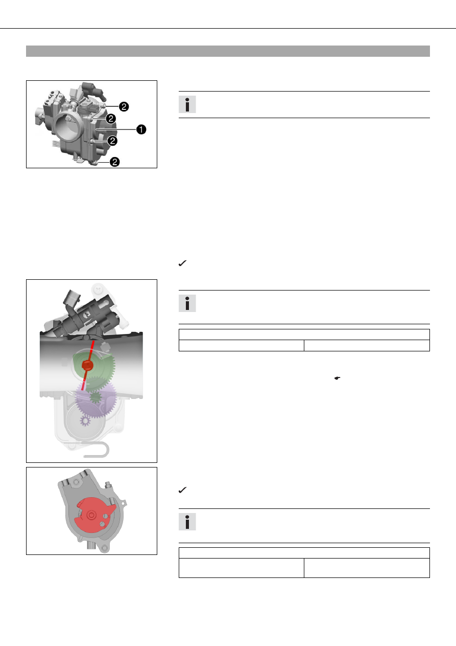
– Ensure that the locking cap

was not opened.

Info

Sealing varnish

on the screws should not be damaged.

» If the sealing varnish is damaged:

– Contact customer service.

– Select model.
– Select "ECU Diagnostics".
– Highlight "EPT throttle motor drive control LC4" control unit.
– Press "Continue".
– Select "Adjustment".
– "Please enter the password:"
– Press "Continue".
– Select "Checking the basic setting of the motor drive".
– Press "Continue".
– Read the information page in the KTM diagnostics tool and use "Continue" to open

the

"Check the throttle position sensor circuit A position" menu.

The motor drive moves the throttle valve to the basic position (completely
closed).

400790-60

– Determine the voltage value via the "Test" button.

Info

The

"Continue" button only appears if the measured value equals the set-

point value.

Throttle position sensor circuit A

Basic position - voltage

"THAD"

0.50… 0.54 V

» If the displayed value is not equal to the setpoint value:

– Close the menu with "Exit".
– Adjust the basic setting of the motor drive. ( p. 166)

400538-51

– Use "Continue" to start the "Checking the emergency position of the throttle valve"

menu.

The motor drive moves the throttle valve to the emergency running position.

– Check the voltage value.

Info

The

"Continue" button only appears if the measured value equals the set-

point value.

Throttle position sensor circuit A

Emergency running position - volt-
age

"THAD"

0.70… 0.74 V

» If the displayed value is not equal to the setpoint value:

– Close the menu with "Exit".

41/THROTTLE VALVE BODY

166

– Adjust the basic setting of the motor drive. ( p. 166)

400537-51

– Use "Continue" to start the "Checking the position of the throttle grip sensor" menu.

The motor drive keeps the throttle valve in the emergency running position.

– Check the voltage value.

Info

The

"Continue" button only appears if the measured value equals the set-

point value.

Throttle grip sensor

Voltage

"APAD"

0.70… 0.74 V

» If the displayed value is not equal to the setpoint value:

– Close the menu with "Exit".
– Adjust the basic setting of the motor drive. ( p. 166)

– Close the menu with "Continue".

25.2

Adjusting the basic setting of the motor drive

Condition
The diagnostics tool is connected.
– Remove the air filter box. (

p. 55)

601136-10

– Disconnect the connector of the motor drive DR

.

– Switch on the ignition by turning the ignition key in the position

(690 Enduro EU, 690 Enduro AUS/UK)

(690 Enduro USA).

– Select model.
– Select "ECU Diagnostics".
– Highlight "EPT throttle motor drive control LC4" control unit.
– Press "Continue".
– Select "Adjustment".
– "Please enter the password:"
– Press "Continue".
– Select "Adjusting the basic setting of the motor drive".
– Press "Continue".

400786-60

– Read the information page in the KTM diagnostics tool and use "Continue" to open

the

"Adjusting the position of the throttle position sensor in circuit A" menu.

41/THROTTLE VALVE BODY

167

601133-10

– Carefully close the throttle valve with your finger and hold it.
– Check the voltage value.

Info

The

"Continue" button only appears if the measured value equals the set-

point value.

Throttle position sensor circuit A

Basic position - voltage

"THAD"

0.50… 0.54 V

» If the displayed value is not equal to the setpoint value:

– Loosen screw

.

– Adjust the throttle position sensor circuit A

by turning to the specified

value.

– Tighten screws

.

– Press "Continue".
– Release the throttle valve.
– Open and close the throttle grip fully ten times.

The

"Continue" button appears.

– Press "Continue".

601133-11

– Carefully close the throttle valve again with your finger and hold it.
– Check the voltage value.

Info

The

"Continue" button only appears if the measured value equals the set-

point value.

Throttle position sensor circuit A

Basic position - voltage

"THAD"

0.50… 0.54 V

» If the displayed value is not equal to the setpoint value:

– Repeat the setting.

– Use "Continue" to start the "Adjusting the emergency position of the throttle valve"

menu.

– Release the throttle valve.
– Fix screws

with locking varnish.

601134-10

– Check the voltage value.

Info

The

"Continue" button only appears if the measured value equals the set-

point value.

Throttle position sensor circuit A

Emergency running position - volt-
age

"THAD"

0.70… 0.74 V

» If the displayed value is not equal to the setpoint value:

– Screw off fuse cover

.

– Loosen nut

.

– Adjust the emergency running position by turning screw

to the specified

value.

– Tighten nut

.

– Mount and tighten fuse cover

.

41/THROTTLE VALVE BODY

168

Loctite

®

648™

Info

Tighten by hand only, do not use a tool.

– Press "Continue".
– Open and close the throttle grip fully ten times.

The

"Continue" button appears.

– Press "Continue".
– Check the voltage value.

Info

The

"Continue" button only appears if the measured value equals the set-

point value.

Throttle position sensor circuit A

Emergency running position - volt-
age

"THAD"

0.70… 0.74 V

» If the displayed value is not equal to the setpoint value:

– Repeat the setting.

601135-10

– Fix fuse cover

with locking varnish.

600946-11

– Use "Continue" to start the "Adjusting the position of the throttle grip sensor" menu.
– Check the voltage value.

Info

The

"Continue" button only appears if the measured value equals the set-

point value.

Throttle grip sensor

Voltage

"APAD"

0.70… 0.74 V

» If the displayed value is not equal to the setpoint value:

– Loosen screws

.

– Adjust the accelerator position sensor

by turning to the specified value.

– Tighten screws

.

– Press "Continue".
– Open and close the throttle grip fully ten times.

The

"Continue" button appears.

– Press "Continue".
– Check the voltage value.

Info

The

"Continue" button only appears if the measured value equals the set-

point value.

Throttle grip sensor

Voltage

"APAD"

0.70… 0.74 V

» If the displayed value is not equal to the setpoint value:

– Repeat the setting.

41/THROTTLE VALVE BODY

169

– Fix screws

with locking varnish.

– Press "Continue".
– Read the information page on the KTM diagnostics tool and, using "Continue", start

the

"ECU Reset" menu.

The control unit is reset.

– Complete the procedure with "Continue".

601136-10

– Switch off the ignition by turning the ignition key in the position

(690 Enduro EU, 690 Enduro AUS/UK)

(690 Enduro USA).

– Plug in the connector of the motor drive DR

.

– Switch to the main menu.
– Switch on the ignition by turning the ignition key in the position

(690 Enduro EU, 690 Enduro AUS/UK)

(690 Enduro USA).

– Select model.
– Select "ECU Diagnostics".
– Highlight "EPT throttle motor drive control LC4" control unit.
– Press "Continue".
– "Read trouble code" selected.
– Complete the procedure with "Back".
– Select "Delete trouble codes".
– Complete the procedure with "Back".

Danger

Danger of poisoning Exhaust gases are poisonous and inhaling them may
result in unconsciousness and/or death.
– When running the engine, always make sure there is sufficient ventila-

tion, and do not start or run the engine in an enclosed space without an
effective exhaust extraction system.

– Start the engine and perform an initialization run.

Guideline

Initialization run

15 min

25.3

Flashing the EFI control unit and/or the EPT control unit

Condition
The ignition is on.
The diagnostics tool is connected and running.

400687-60

EFI control unit

– Select model.
– Select "ECU Diagnostics".
– Highlight the "Injection management EFI LC4" control unit.
– Press "Continue".
– Select "ECU Flashing".
– "Please enter the password:"
– Press "Continue".
– Read the safety instructions and create the necessary preliminary conditions.
– Confirm the instructions by clicking on "OK".
– Press "Select file" and select a new mapping.

Info

"The BLZ file and the exhaust system must match!"

– Press the "ECU flash process" button.
– Read the prompt and confirm with "OK".

The new mapping is loaded.

– Switch to the main menu.

41/THROTTLE VALVE BODY

170

EPT control unit

– Select model.
– Select "ECU Diagnostics".
– Highlight "EPT throttle motor drive control LC4" control unit.
– Press "Continue".
– Select "ECU Flashing".
– "Please enter the password:"
– Press "Continue".
– Read the safety instructions and create the necessary preliminary conditions.
– Confirm the instructions by clicking on "OK".
– Press "Select file" and select a new mapping.

Info

"The BLZ file and the exhaust system must match!"

– Press the "ECU flash process" button.
– Read the prompt and confirm with "OK".

The new mapping is loaded.

Info

Start the engine and perform an initialization run.

25.4

Requesting the enabling code

Condition
The changed EFI control unit and/or the EPT control unit is connected.
The ignition is on.
The diagnostics tool is connected and running.
Flashing of the EFI control unit and/or the EPT control unit is completed.

400687-60

– Select model.
– Select "ECU Diagnostics".
– Highlight the "Injection management EFI LC4" control unit.
– Press "Continue".
– Select "Coding".
– "Please enter the password:"
– Press "Continue".
– Select "Change VIN - New identity".
– Press "Continue".
– Read the information page on the KTM diagnostics tool and, using "Continue", start

the coding process.

– Overwrite the entry under "Please enter VIN:" with the new chassis number.

Info

For used control units, the chassis number programmed last is displayed.

– Press "Continue".
– Select "Code form".
– Press "Print".

The protocol is being printed out.

– Fill out the protocol and send to "diagnostic@ktm.com".

A response mail containing the enabling code arrives.

41/THROTTLE VALVE BODY

171

25.5

Coding the EFI control unit and/or EPT control unit

Condition
The ignition is on.
The diagnostics tool is connected and running.
Flashing of the EFI control unit and/or EPT control unit is completed.
For a used control unit

– Request the enabling code. (

p. 170)

400687-60

EFI control unit

– Switch to the main menu.
– Select model.
– Select "ECU Diagnostics".
– Highlight the "Injection management EFI LC4" control unit.
– Press "Continue".
– Select "Coding".
– "Please enter the password:"
– Press "Continue".
– Select "Change VIN - New identity".
– Press "Continue".
– Read the information page on the KTM diagnostics tool and using "Continue"

start the coding process.

– Under "Please enter VIN:" enter the new VIN.

Info

For new control units, a sample VIN is displayed.
For used control units, the last programmed VIN is displayed.

– Press "Continue".
– Select "Code entry".
– "Please enter the code"
– Press "Continue".

The new VIN is written to the EFI control unit.

– Switch to the main menu.
– Select "Show identification".
– Compare the old VIN to the new VIN.

The new VIN is shown.

EPT control unit

– Select model.
– Select "ECU Diagnostics".
– Highlight "EPT throttle motor drive control LC4" control unit.
– Press "Continue".
– Select "Coding".
– "Please enter the password:"
– Press "Continue".
– Read the information page on the KTM diagnostics tool and using "Continue"

start the coding process.

– Under "Please enter VIN:" enter the new VIN.

Info

For new control units, a sample VIN is displayed.
For used control units, the last programmed VIN is displayed.

– Press "Continue".
– Select "Code entry".
– "Please enter the code"
– Press "Continue".

The new VIN is transferred to the EPT control unit.

41/THROTTLE VALVE BODY

172

– Switch to the main menu.
– Select "Show identification".
– Compare the old VIN to the new VIN.

The new VIN is shown.


Content   ..  19  20  21  22   ..