KTM LC4 400-660LC42003 engine. Manual - part 23
 

  Index      Manuals     KTM LC4 400-660LC42003 engine. Repair Manual


Search            


Content   ..  21  22  23  24   ..


KTM LC4 400-660LC42003 engine. Manual - part 23


8-40D

Disassembling the carburetor Keihin FCR - MX 41

NOTE: Before you start disassembling the carburetor, you should look
for a clean workplace. It should offer you enough space to lay out all
individual components of the carburetor in perfect order.

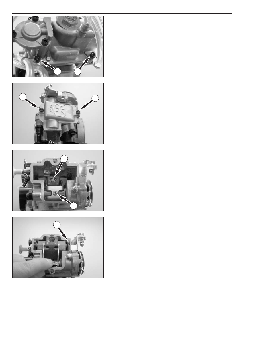
– Dismount the carburetor and remove any coarse dirt.

– Loosen both bolts 

1

and remove all of the vent hoses from the

carburetor.

– Remove both bolts 

2

and remove the slide cover and gasket from

the carburetor.

– Remove screw 

3

and pull the jet needle out of the throttle slide.

– Remove screw 

4

.

– Pull the throttle slide arm up and take the throttle slide roller 

5

and

the slide shim out of the carburetor.

1

1

2

2

4

3

5

8-41D

Repair manual  KTM LC4 

Art.-Nr

.  3.206.006 -E

– Turn the carburetor around, remove the 3 screws and remove the

cover of the accelerator pump.

NOTE: When dismounting the cover, watch out for the spring and the
sealing rings as they may get lost easily.

– Remove the 2 sealing rings, the spring and the diaphragm from the

pump housing.

– Remove the screws on the float chamber and remove the housing.

– Pull out the float hinge pin 

1

and remove the float together with

the float needle valve.

– Remove the main jet 

2

.

– Remove the screw 

3

and use pliers to carefully extract the seat of

the float needle valve from the carburetor.

– Screw out the idling jet 

4

, the starting jet 

5

and the needle jet 

6

.

– Turn in the mixture control screw 

7

down to the stop, count the

number of turns and write it down.

– Turn out the mixture control screw and dismount it together with the

spring, the washer, and the O-ring.

NOTE: The spring, the washer, and the O-ring will usually remain in the
bore. These parts can be removed with the help of compressed air.

1

2

3

7

5

4

6

8-42D

– Remove bolts 

1

and the throttle sensor 

2

.

NOTE: the throttle sensor should only be dismounted if defective. If the
bolts 

1

are loosened, the throttle sensor must be adjusted again.

– Remove screw 

3

and pull the connecting piece out of the

carburetor.

– Remove the 2 screws and take the intake trumpet together with the

O-ring 

4

off the carburetor.

– Unscrew the idle-air jet 

5

and the main air jet 

6

.

– Thoroughly clean all jets and other parts and blow compressed air

through them.

– Clean the carburetor housing and blow compressed air through all

the ducts in the carburetor.

– Check all gaskets for damage and, if necessary, replace them.

6

3

1

1

2

4

5

8-43D

Repair manual  KTM LC4 

Art.-Nr

.  3.206.006 -E

Checking the choke slide and hot start knob

Choke slide:
The choke slide must be easy to actuate .
The piston 

1

of the choke slide must not have any pronounced score

marks or deposits.

Hot start knob:
The hot start knob must be easily actuated.
The piston on the hot start knob may not have any scores or deposits.

Checking the accelerator pump

Check the membranes for cracking or brittleness.
Check gaskets for damage.
Check if the bores 

2

are unobstructed.

Checking the jet needle

Check the jet needle for bending and wear.

Checking the float needle valve

Check the sealing surface of the needle valve for notches.
There must not be any dirt between the valve seat and the float needle.

Checking the throttle valve

The rollers 

3

at the throttle valve must be easy to turn and must not

have any flat spots.
Check the throttle valve paddles 

4

for damage.

1

2

2

4

3

8-44D

Assembling the carburetor Keihin FCR-MX 41

– Mount the idle-air jet 

1

and the main air jet 

2

.

– Place the O-ring 

3

in the groove and secure the intake trumpet to

the carburetor by means of the 2 screws.

– Insert the fuel port in the carburetor and fix with screw 

4

.

NOTE: In the mounted state, the connection piece must be easy to
turn.

– Mount the choke slide 

5

, the hot start knob 

6

and actuate several

times, checking for smooth operation. Also make sure the choke and
the hot start knob lock into place.

– Thread the spring, the washer and the O-ring onto the mixture

control screw 

7

and screw the mixture control screw in as far as it

will go.

– Now, unscrew the mixture control screw the number of turns written

down during disassembly.

NOTE: See the Technical Specifications for the basic carburetor setting.

– Mount idling jet 

8

, starting jet 

9

and needle jet together with main

jet 

bk

.

– Insert the needle valve seat 

bl

in the bore and fix with screw 

bm

.

5

11

3

2

1

4

7

8

9

6

10

12

8-45D

Repair manual  KTM LC4 

Art.-Nr

.  3.206.006 -E

– Position the float and the float needle valve and mount the float

hinge pin 

1

.

– Check the float level (see page 8-21).

– Mount the float chamber and the gasket, position the bracket for the 

adjustment screw 

2

and fix the float chamber with the screws 

3

.

NOTE: When positioning the float chamber, make sure that the push
rod 

4

of the accelerator pump slides into the bore.

– Place the membrane 

5

with the labeling facing upwards and the

spring into the pump housing.

– Place the O-ring 

6

into the groove. Secure the sealing ring 

7

with

some grease in the cover and fasten the cover by means of 3 screws.

– Mount the throttle valve sensor such that the flat spot at the 

carburetor engages the groove of the throttle valve sensor and
secure it by means of the bolt.

– Pull up the throttle slide arm, push the throttle slide together with

roll 

8

and the slide shim into the carburetor so that the rolls 

9

engage in the throttle slide (see illustration).

– Check the throttle slide for smooth operation.

5

1

3

2

4

6

7

8

9

8-46D

– Apply Loctite 243 to the screw 

1

and tighten.

– Mount the jet needle and fix with the screw 

2

.

– Position the slide cover with the gasket and fasten with the 2 screws

3

.

– Fix the vent hoses on the float chamber with the 2 bolts 

4

.

1

2

3

3

4

4

8-47D

Repair manual  KTM LC4 

Art.-Nr

.  3.206.006 -E

Adjusting the position of the throttle valve sensor

NOTE: Before checking the position of the throttle valve sensor, you
have to adjust the idle speed correctly.

– Disengage the plug-and-socket connection of the throttle valve

sensor.

– Connect a multimeter (measuring range Ω x 1k) to the blue (+) and

the black (-) cable of the throttle valve sensor and measure the
throttle valve resistance.

– Now, multiply this value by 0.15. This yields the adjustment value for

the throttle valve sensor.

Example:
Throttle valve sensor resistance (bl/s) = 5kΩ

Throttle valve sensor resistance (ge/s) = 

5 kΩ x 0.15 = 750 Ω ± 50 Ω

– Connect the multimeter (measuring range Ωx100) to the yellow (+)

and the black (-) cable of the throttle valve sensor and measure the
throttle valve sensor resistance with the throttle grip closed.
According to the above example, this value should be 750Ω ± 50Ω.

– If the value measured does not correspond to the desired value,

loosen the 2 bolts 

1

and turn the throttle valve sensor 

2

until the

instrument displays the desired value.

– Secure the throttle valve sensor in this position by fastening the bolts

and check the value once more.

– Connect the throttle valve sensor to the wiring harness.

bl

bl

ge

ge

s

s

1

1

2

bl = blue
ge = yellow
s = black


Content   ..  21  22  23  24   ..