KTM LC4 400-660LC42003 engine. Manual - part 19
 

  Index      Manuals     KTM LC4 400-660LC42003 engine. Repair Manual


Search            


Content   ..  17  18  19  20   ..


KTM LC4 400-660LC42003 engine. Manual - part 19


8-8D

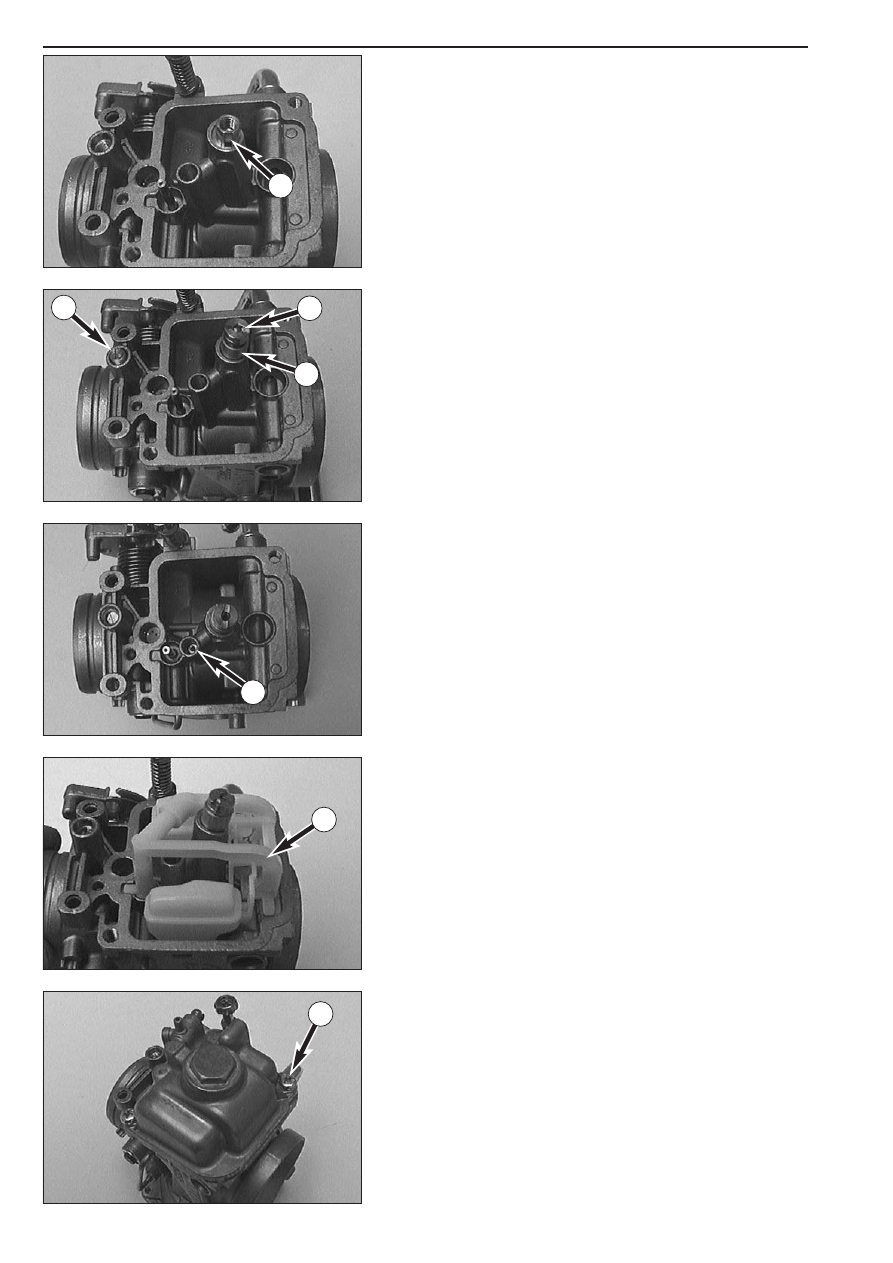
Assembling the carburetor (Mikuni BST 40)

– Put the needle jet into the carburetor, making sure that the flat

portion 

A

is located next to the jet needle.

– Put the distance bushing 

1

onto the needle jet and mount the main

jet 

2

.

– Mount the spring, the washer and a new O-ring on the mixture

adjusting screw 

3

and twist the mixture adjusting screw all the way

in.

– Then twist the mixture adjusting screw back out, applying the same

number of twists you have written down when disassembling the
device.

– Mount the idling jet 

4

.

– Insert the float unit 

5

into the carburetor.

– Mount the float chamber together with a new gasket and tighten

both screws 

6

.

A

1

2

3

4

5

6

Repair manual  KTM LC4 

Art.-Nr

.  3.206.006 -E

8-9D

– Mount the throttle slide, making sure that the membrane of the

throttle slide rests properly against the round wall of the carburetor
housing.

– Insert the spring into the throttle slide.

– Put the throttle stop 

1

into the membrane cover.

NOTE: The throttle stop shown in the picture is fitted in a restricted
version.

– Mount the membrane cover and fasten it with the two screws 

2

.

Checking the throttle sensor (from model 2003 on)

NOTE: the adjustment must be made in a mounted condition with the
cable connected and the ignition switched on.

– Use a digital multimeter to measure the voltage between the black

and yellow cables at the connector 

3

(CDI).

!

CAUTION

!

S

INCE YOU MUST MEASURE WITH THE CONNECTOR ATTACHED

MAKE SURE TO

CAREFULLY PUSH THE MEASURING TIPS ON THE MULTIMETER THROUGH THE SEALING
FROM THE CABLE SIDE AND NOT TO DAMAGE ANY PART OF THE CONNECTOR

.

– Reading with closed throttle (neutral position): 0.88 +/- 0,075 volts
– Slowly open the throttle valve with the throttle grip, the measured

voltage should increase uniformly up to the full load reading.

Reading with fully opened throttle grip (full throttle position): 

3,88 +/- 0,1 volts.

Adjusting the throttle sensor

– Loosen the screw on the throttle sensor 

4

and turn the throttle

sensor until you reach the reading for the neutral position.

– Tighten the screw on the throttle sensor.

2

2

1

4

3

8-10D

3-5 mm

1

2

3

4

5

6

7

Adjust idling speed

NOTE: Warm up the engine before adjusting the idle speed.

Use the adjusting screw 

1

to adjust the basic position of the throttle

valve and, thus, the idle speed. Turning in clockwise direction will
increase the idling speed, turning in counterclockwise direction will
reduce the idling speed. Normal idling speed 1400 - 1500 rpm.

Adjusting the throttle cable

A play of 3-5 mm must at any time be left in the throttle cables. To
check the play of the throttle cables, first push back the protective cap

2

on the throttle twist grip. Now it should be possible to lift the outer

sleeve of one of the two cables 3-5 mm off the adjusting screw 

4

before resistance is felt. The play of the throttle cables can be adjusted,
if necessary, using the two adjusting screws.
For this purpose, undo counter nut 

3

and turn the adjusting screw until

the desired play is achieved. Then tighten the counter nut and replace
the protective cap.

After adjusting the throttle cables turn the handlebar all the way to the
left and to the right while the engine is still running. The idle speed
should not change.

Check float level

Take off the float chamber, press down the float frame and hold
carburator as shown in the picture. The float 

5

mooves downwards.

Turn carburator slowly until the float moves towards the carburator. In
this position the edge of the float 

6

must be parallel to the sealing

surface of the carburator 

7

.

CAUTION

!

I

F YOU HOLD ON TURNING THE CARBURATOR

THE FLOAT WILL PRESS AGAINST THE

SPRING OF THE NEEDLE VALVE AND A CORRECT CHECK IS NOT POSSIBLE

. I

N THAT

CASE THE CARBURATOR IS TO BE TURNED BACK AND THE CHECK MUST BE DONE
TWICE

.

If the two edges are not parallel, correction can be done by bending the
lever of the needle valve. At the end a check is necessary again.

Repair manual  KTM LC4 

Art.-Nr

.  3.206.006 -E

8-11D

CARBURETOR – DELL’ORTO PHM 40 SD

Disassembling the carburetor (Dell’Orto PHM 40 SD)

NOTE: Before commencing to disassemble the carburetor make sure
that your workplace is clean and large enough to properly arrange all
carburetor components before you.

– Remove the two screws and pull the carburetor cover out of the

carburetor together with the throttle slide.

– Wrap the throttle slide in a clean piece of cloth and put it onto the

air filter box.

– Undo screw 

bk

and take the starting piston out of the carburetor.

– Remove the plug 

1

together with the seal ring and take off the float

chamber.

– Remove the main jet 

2

, the main jet holder 

3

and the baffle 

4

.

– Twist out the starting jet 

5

.

– Remove the idling jet 

6

together with the idle mixture pipe below.

– Twist out the needle jet 

7

.

– Pull out the pin 

8

and remove the float.

– Remove the entire needle valve 

9

together with the gasket behind.

8-12D

1

2

3

4

5

6

7

8

9

10

Repair manual  KTM LC4 

Art.-Nr

.  3.206.006 -E

– Twist the mixture adjusting screw 

1

clockwise all the way in,

counting and writing down the number of twists. Twist out the
mixture regulating screw and remove it together with the spring, the
washer and the O-ring.

– Twist the adjusting screw 

2

clockwise all the way in, counting and

writing down the number of twists. Twist out the adjusting screw
and remove it together with the spring, the O-ring and the washer.

– Remove screw 

3

, and take off the hose connection together with

the fuel filter 

4

.

– Clean all jets and other components and blow them through with

compressed air.

– Clean the carburetor housing and use compressed air to blow

through all ducts within the carburetor.

– Check all gaskets for damage and exchange them, if necessary.

Assembling the carburetor (Dell’Orto PHM 40 SD)

– Put the spring, the washer and the O-ring onto the mixture adjusting

screw 

1

and twist the mixture adjusting screw all the way in.

– Twist out the mixture adjusting screw, applying the same number of

twists previously written down during the disassembly of the device.

– Put the spring, the washer and the O-ring onto the adjusting screw

2

and twist the adjusting screw all the way in.

– Twist out the adjusting screw, applying the same number of twists

previously written down during the disassembly of the device.

– Insert the fuel filter into the carburetor. Properly position the hose

connection and mount screw 

3

together with the seal ring.

– Insert the seal ring into the carburetor bore and mount the needle

valve 

5

.

8-13D

1

2

3

1

2

3

3

4

5

– Position the float and mount the pin 

1

. When mounting the float

make sure that the needle valve properly engages with the float.
Check by moving the float upwards: the needle valve must move
with the float.

– Mount the idling mixture pipe and the idling jet 

2

.

– Mount the needle jet 

3

.

– Position the baffle 

4

and fasten it with the main jet holder 

5

.

– Mount and tighten the main jet 

6

.

– Mount and tighten the starting jet 

7

.

Check the O-ring 

8

in the float chamber for proper fit.

– Position the float chamber and fasten it with the plug 

9

. Do not

forget the seal ring.

8-14D

1

2

3

4

5

6

7

8

9

Repair manual  KTM LC4 

Art.-Nr

.  3.206.006 -E

8-15D

CARBURETOR – DELL’ORTO PHM 38 ND


Content   ..  17  18  19  20   ..