KTM LC4 400-660LC42003 engine. Manual - part 13
 

  Index      Manuals     KTM LC4 400-660LC42003 engine. Repair Manual


Search            


Content   ..  11  12  13  14   ..


KTM LC4 400-660LC42003 engine. Manual - part 13


7-11D

Electric Starter system

NOTE: The electric starter system is equipped with a safety mechanism.
Starting is possible only in the following conditions:

● ignition lock in position       or  
● emergency OFF switch in position 
● transmission set to idle, or clutch is pulled

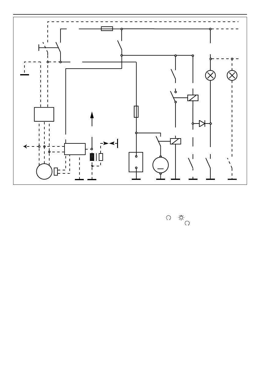
Function of the electric starter system:
From the battery 

1

, battery voltage is supplied via the ignition lock 

2

and the emergency OFF switch 

3

to the coil of the auxiliary starter

relay 

4

and the tip switch 

5

.

The contact of the auxiliary starter relay will enable starting only if at
least one of the following conditions is met :

● transmission is set to idle (idle switch 

6

closed)

● clutch is pulled (clutch switch 

7

closed)

If the tip switch 

5

is actuated, the electric starter motor 

9

is turned on

by way of the starter relay 

8

.

bl  . . . . . . . . .blue
br  . . . . . . . . .brown
ge  . . . . . . . .yellow
gr  . . . . . . . . .grey
g   .  . . . . . . . .green
o  . . . . . . . . .orange
r   .  . . . . . . . . .red
ra  . . . . . . . . .pink
s . . . . . . . . . .black
v  . . . . . . . . .violet
w  . . . . . . . . .white

G

M

1

2

3

4

5

6

7

8

9

1

Battery

2

Ignition lock

3

Emergency off switch

4

Auxiliary relay

5

Tip switch built in emergency off switch

6

Neutral switch

7

Clutch switch

8

Starter relay

9

Starter motor

ge-r

ge-bl

o

r

s

ge-bl

ge

ge

r-

w

bl-w

g-s

br

to EPC control

unit

20 A

10 A

Repair manual  KTM LC4 

Art.-Nr

.  3.206.006 -E

7-12D

Check start auxiliary relay

– Remove headlight mask and remove the start auxiliary relay.

– Connect the start auxiliary relay to a 12 V battery as shown in the

illustration.

– Use an ohmmeter to measure the continuity between the terminals

A

and 

B

.

Reading 0 Ω relay intact

Reading ∞ Ω relay defect

Checking the auxiliary starting relay for faultless operation

Preparation:
– Pull the auxiliary starter relay out of its holder.
– Connect an ohmmeter or a continuity tester to the cables of the

auxiliary starting relay (colors: red and red/white).

– Perform the tests in the order indicated below. The auxiliary starting

relay must respond  in either of the following two cases:

● Put in a gear and slowly  pull the clutch lever. The auxiliary starting

relay should respond when the lever is pulled approximately half of
the overall distance. If this is not the case, please check the clutch
switch. Keep an eye on the neutral control lamp while performing
this test. The neutral control lamp should not light up. If it lights up,
check the diode.

● Switch the transmission to neutral without previously pulling the

clutch. The auxiliary starting relay should now connect and be
tripped as soon as a gear is put in. If this is not the case, please
check the diode and the neutral switch.

NOTE: Connecting of the auxiliary starting relay is always accompanied
by a faint clicking sound. The ohmmeter or continuity tester indicates
continuity while the auxiliary starting relay is on.

Checking the diode

NOTE: Diodes conduct current only in the direction indicated by the
arrow, preventing the conduction of current in the opposite direction.

Two different kinds of diode defects can be distinguished:
– The diode conducts no current at all.
– The diode conducts current in both directions.
Diode defects can lead to different kinds of trouble, depending on the
type of defect.

NOTE: The diode is located in a 2-pole connector.

Checking for faultless operation:
– Remove the headlight mask.
– Pull the diode 

2

out of the connector.

– Connect an appropriate ohmmeter to the diode and check for

continuity.

– Connect the ohmmeter in the opposite direction and check if the

diode prevents current conduction in the opposite direction.

A

B

1

2

7-13D

Checking the starter relay

– Remove the seat and the right side cover and disconnect the

combination connector 

1

of the starter relay.

– Disconnect negative terminal at battery and the two cables at the

starter relay.

– Connect the starter relay to a 12 V battery as indicated in the

diagram.

– Check continuity between terminals 

C

and 

D

using an ohmmeter.

Reading: 0 Ω OK

Reading: ∞  Ω   defect

NOTE: The response of the starter relay is accompanied by a faint
clicking sound.

Checking the electric starter motor

– Switch off the ignition.
– Disconnect the negative pole of the battery and remove the electric

starter motor.

– Connect the negative pole of a 12 V battery to the housing of the E

starter motor and briefly connect the positive pole of the battery to
connection 

2

of the electric starter motor (use thick cables).

– The starter must turn as soon as the circuit is closed.
– If this is not the case, replace the starter motor.

1

C

D

2

Repair manual  KTM LC4 

Art.-Nr

.  3.206.006 -E

7-14D

Checking the clutch switch

– Disconnect the clutch switch from the cable tree.
– Connect the ohmmeter to the 2-pole connector 

2

(cable colors:

yellow/yellow) of the clutch switch and slowly pull the clutch lever.

– The switch must connect when the lever is pulled approximately half

of the overall distance.

Checking the tip switch and the emergency OFF switch

– Remove the headlight mask.
– Disconnect the 4-pole connector 

3

of the tip switch/emergency OFF

switch from the cable tree.

– Use an ohmmeter and test both switches according to the table

below (please refer to the sketch for the configuration of the
connector).

– Then check all lines for ground contact.

Trouble shooting in the electric starter system

When the starter motor fails to turn upon operation of the tip switch,
perform the following checks first:

● Is the ignition lock in position       or         ?
● Is the emergency OFF switch position       ?
● Is the neutral control lamp on while the ignition is on?
● Can the engine be started with the clutch pulled?
● Is the battery charged?
● Has the main fuse blown?
● Has the fuse for startsystem and ignition blown?
● Fuse for starter system and ignition has melted?

● Check the auxiliary starting relay
● Check the starter relay
● Check the electric starter motor

Circuit

Position

Condition

Emergency off switch

duct

Emergency off switch

no duct

Tip switch

operated

duct

Tip switch

not operated

no duct

start

switch

emergenc

y off

switch

2

3

7-15D

G

M

Ignition system

From the battery 

1

, battery voltage is delivered via the main fuse 

2

,

through the activated ignition lock 

3

and the activated emergency OFF

switch 

4

to the CDI unit 

6

.

During each revolution of the crankshaft, the pulse generator 

7

supplies a signal to the CDI unit 

6

. In the CDI unit, this signal is

processed so as to calculate the ignition point.
This ignition pulse is passed on to the ignition coil 

8

(the ignition spark

is produced).

The ignition system is a digital high voltage capacitor ignition that
receives its power supply from the battery. Therefore, it works only with
an intact battery.
When the battery is discharged below the threshold level, the voltage
can, due to the starting process, drop below the minimum supply
voltage required by the ignition. In this case, turn off the light, and use
the kickstarter.

CAUTION

!

S

AFE AND FAULTLESS OPERATION OF THE DIGITAL IGNITION REQUIRES SPARK PLUG

CONNECTORS AND SPARK PLUGS WITH INTEGRATED RESISTANCE TYPE SUPPRESSORS

.

bl  . . . . . . . . .blue
br  . . . . . . . . .brown
ge  . . . . . . . .yellow
gr  . . . . . . . . .grey
g   .  . . . . . . . .green
o  . . . . . . . . .orange
r   .  . . . . . . . . .red
ra  . . . . . . . . .pink
s . . . . . . . . . .black
v  . . . . . . . . .violet
w  . . . . . . . . .white

1

2

3

4

6

to EPC-control-

unit

7

8

1

Battery

2

Main fuse (20 A)

3

Ignition lock

4

Emergency-off switch

5

Auxiliary relay

6

CDI

7

Pulse generator

8

Ignition coil

s-r

r-s

bl-w

s

w

g

Repair manual  KTM LC4 

Art.-Nr

.  3.206.006 -E

7-16D

CDI unit

Check the cables and plug and socket connections of the CDI unit 

1

.

The CDI unit function can only be checked on an ignition test bench.

CAUTION

!

N

EVER USE A COMMERCIAL MEASURING DEVICE TO CHECK THE

CDI 

UNIT

.

C

OMMERCIAL MEASURING DEVICES CAN DESTROY HIGHLY SENSITIVE ELECTRONIC

COMPONENTS

.

Checking the ignition coil

– Disconnect all cables and remove the spark plug connector.
– Use an ohmmeter to measure the following values.

NOTE: The indicated setpoint values correspond to a temperature of
20° C.

Replace the ignition coil if the measured values deviate significantly
from the setpoint values.

Trouble shooting in the ignition system

Before checking the ignition system check:

● if the ignition lock is in position       or
● if the emergency off switch is in position
● if the neutral control lamp is on
● if the motorcycle can be started with the clutch pulled
● if the battery is charged
● the main fuse

Check if an ignition spark is produced when the starter is operated.
Proceed as follows:
– Pull off the spark plug connector.
– Disconnect the spark plug connector from the ignition cable.
– Hold the free end of the ignition cable approximately 5 mm from

ground.

– A  strong spark should be visible when the electric starter is now

operated. If the battery level is low, turn off the light, and use the
kick starter.

– If a spark is visible, replace the spark plug connector.
– Twist out the spark plug and insert it into the spark plug connector.
– Connect the spark plug to ground. A strong spark should be visible

at the electrode when the electric starter is now operated. If this is
not the case, the spark plug connector or the spark plug is defect.

– If no spark is produced during the first test, perform the following

checks:

● Does the ignitionís power supply line (orange) carry battery voltage?

● If this is not the case, check the ignition lock, the emergency OFF

switch and, if applicable, the side stand relay as well as the
corresponding parts of the cable tree.

– If the ignition is sufficiently supplied with power and no spark is

produced, check:

● ground connection of CDI unit and ignition coil

● the cable between CDI unit and ignition coil

● pulse generator

● stator

● ignition coil

NOTE: The CDI unit can’t be tested with simple devices. It can only be
replaced. It can only be tested on an ignition test bench.

1

2

RESISTANCE

0,425 – 0,575 Ω

10,80 – 16,20 kΩ

MEASUREMENT

primary coil

secondary coil

COLOURS

blue/white – ground

blue/white – ignition wire

7-17D

EPC system

Function:
From the battery 

1

, battery voltage is supplied to the EPC controller 

5

via the main fuse 

2

, the activated ignition lock 

3

, and the fuse 

4

.

The blue/white cable leading to the ignition coil 

6

provides an r.p.m.

signal to the EPC controller 

5

. Using this signal, the EPC controller will

then calculate the current speed.

When the throttle grip is opened all the way (microswitch 

9

closes) at

a certain speed, the EPC controller will activate the solenoid valve 

bk

,

provided that either the 2nd or the 3rd gear has been engaged.
By opening the solenoid valve 

bk

, a dosed amount of fresh air will get

to the upper end of the slide membranes of the carburetor. This causes
the throttle slide to open slowly. Thereby, the operating noise of the
motorbike is reduced.

NOTE: If malfunctions develop in the EPC system, the EPC controller
can be unplugged. This will not cause damage to any other parts of the
motorcycle.

bl  . . . . . . . . .blue
br  . . . . . . . . .brown
ge  . . . . . . . .yellow
gr  . . . . . . . . .grey
g   .  . . . . . . . .green
o  . . . . . . . . .orange
r   .  . . . . . . . . .red
ra  . . . . . . . . .pink
s . . . . . . . . . .black
v  . . . . . . . . .violet
w  . . . . . . . . .white

1

Battery (12V / 8 Ah)

2

Main fuse (20 A)

3

Ignition lock

4

Fuse for ignition and start system

5

EPC-control unit

6

Ignition lock

7

Contact screw 2nd gear

8

Contact screw 3rd gear

9

Micro switch

bk

Solenoid valve

7

8

6

1

2

3

4

5

10

9

br

bl-s

s-o

r-s

g-r

ge-bl

br

bl-w

Repair manual  KTM LC4 

Art.-Nr

.  3.206.006 -E

7-18D

Dismount / renew solenoid valve for EPC

– Remove seat, side covers, and tank with spoilers.
– Unplug the solenoid-valve connector.
– Disconnect the two hoses, and pull solenoid valve 

1

upwards and

out of the holder.

– Insert new solenoid valve into the holder.
– Connect the two hoses, and plug in connector.

Check of solenoid valve for EPC

NOTE: When you turn on the ignition, the solenoid valve must open for
approx. 1 second. During this process, you can hear a slight clicking
noise.

– For checking, disconnect the 2-pole connector 

2

at the solenoid

valve.

– Now, connect a 12V battery to both terminals of the solenoid valve.
– When closing the power circuit, a clicking noise must be audible in the

solenoid valve (the membrane opens).

– If you cannot hear any clicking noise, you have to replace the solenoid

valve.

Controller of the EPC system

NOTE: The controller 

3

cannot be checked by means of standard

measuring methods.

If malfunctions develop in the EPC system, start by checking:

solenoid valve
microswitch
plug-and-socket connection 

4

and cables

contact screws at engine
hose from magnetic valve to carburetor

– If the above components are okay, the controller has to be replaced.

CAUTION

!

B

EFORE CONNECTING THE CONTROLLER

IT IS ABSOLUTELY NECESSARY THAT YOU

TURN OFF THE IGNITION

. O

THERWISE

MALFUNCTIONS IN THE ELECTRONIC SYSTEM

MAY DEVELOP

.

1

2

3

4


Content   ..  11  12  13  14   ..