KTM LC4 400-660LC42003 engine. Manual - part 5
 

  Index      Manuals     KTM LC4 400-660LC42003 engine. Repair Manual


Search            


Content   ..  3  4  5  6   ..


KTM LC4 400-660LC42003 engine. Manual - part 5


4-12D

Repair manual  KTM LC4 

Art.-Nr

.  3.206.006 -E

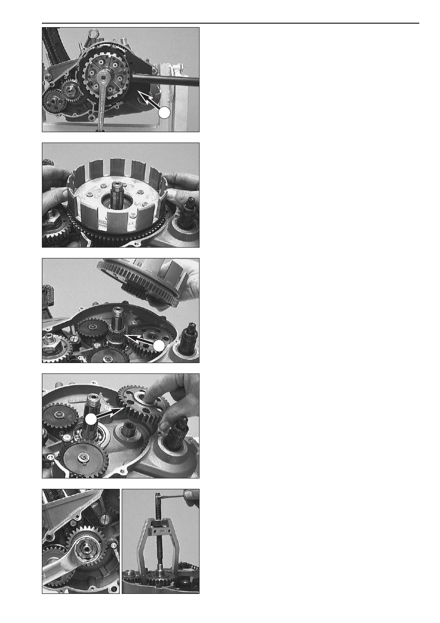
– Release the lock washer of the inner clutch hub.
– Put the clutch holder 

1

onto the inner clutch hub and undo the

hexagon nut (see illustration).

– Remove the clutch holder.
– Take the hexagon nut, the lock washer and the inner clutch hub off

the main shaft.

– Try to turn the outer clutch hub in both directions to check the

absorbing elements. Dead travel in either direction is inadmissible.

– Take the outer clutch hub and the needle bearing 

2

off the main

shaft.

– Remove the kickstarter intermediate gear 

3

.

– Unscrew hexagon nut of primary gear wheel and detach spring

washer from the crankshaft.

– Fit extractor for primary gear and pull off primary gear.

1

2

3

4-13D

– Remove the balancer shaft from the bearing by hand.

Removing the oil pumps

NOTE: The following procedure must always be performed on both oil
pumps.

– Remove the locking washer 

1

.

– Remove stop disc 

2

and the oil pump gear 

3

.

– Remove the needle roll 

4

and stop disc 

5

.

– Twist out the 6 bolts 

6

and remove the oil pumps from the housing.

NOTE: For better access to bolt 

7

remove bolts 

8

and take off the

retaining bracket.

1

2

4

6

7

3

5

8

4-14D

Repair manual  KTM LC4 

Art.-Nr

.  3.206.006 -E

Removing the timing chain and the timing gear

– Remove allan head bolt 

1

and remove timing chain guide from the

casing.

– Unscrew flat-head screw 

2

and remove timing chain tensioner.

– Unscrew allan head bolt 

3

and remove timing chain securing guide.

– Insert timing chain into the clutch compartment of the engine

housing and disengage from timing gear.

– Remove the primary gear woodruff key 

4

from the crankshaft.

– Withdraw the timing pinion from crankshaft with a 2-jaw puller.
– Take the woodruff key of the timing gear out of the crankshaft.

Removing the clutch release shaft

– Remove bolt(s) 

5

and take off the retaining bracket 

6

.

– Pull the clutch release shaft 

7

out of the housing.

– Remove the grooved ring 

8

.

1

2

3

4

5

6

7

8

4-15D

Parting of engine housing

– Loosen the crankshaft locking bolt.
– Tip ignition side upwards and remove all the housing bolts.
– Release engine mount on engine repair stand.
– Lift right hand housing half with suitable tools bearing on the bosses

provided, or part with a few light plastic mallet blows against the
counter shaft.

CAUTION

!

L

EVERING APART WITH A SCREW

-

DRIVER OR SIMILAR TOOL MUST BE AVOIDED

SINCE

THE SEALING SURFACES ARE EASILY DAMAGED

.

– Remove housing-half and gasket.

– Take the stop disc 

1

off the main shaft (can stick to the inside of the

housing).

– Take the O-ring 

2

off the countershaft.

– Remove the crankshaft from the bearing by hand.

– Take the inner ring 

3

of the roller bearing and the O-ring below 

4

off the countershaft.

Removing the shift mechanism

– Push back slide plate 

5

and pull shift shaft out of the kickstarter

shaft.

– Remove allan head bolt 

6

and detach locking piece.

1

2

3

4

5

6

4-16D

Repair manual  KTM LC4 

Art.-Nr

.  3.206.006 -E

– Remove the 3 bolts 

1

and detach the shift mechanism support 

2

.

– Pull out the shift rails 

3

and swing the shift forks aside, taking care

of the shift rolls 

6

on the driving pins of the shift forks.

– Pull the shift roller 

4

out of the  bearing seat. 

– Take the shift forks 

5

together with the shift rolls 

6

out of the

engine housing.

NOTE: Although the counter shaft shift forks are identical they should
be refitted in the same position as before if reused. Therefore mark
accordingly upon removal.

1

1

2

3

3

4

5

6

4-17D

Removing the transmission shafts

– Pull both transmission shafts out of the bearing seats.

– Take the 3rd gear/sliding gear and the 1st gear/idler gear out of the

engine housing together with the needle bearing and the stop disc.

NOTE: A roller bearing was installed in the 660 SMC model, thus a stop
disc is unnecessary.

Removing the kickstarter shaft

– Put kickstarter onto kickstarter shaft and hold in this position.
– Unscrew stop bolt 

1

and relieve starter spring tension by releasing

the kickstarter.

– Remove kickstarter shaft assembly from housing.

– Take the starter gear out of the housing bag together with the

needle bearing and the stop discs.

– Clean all parts and check for wear, replace if necessary.

NOTE: When an engine is completely overhauled it is recommended
that all gaskets, shaft seal rings, O-rings and, possibly, all bearings are
renewed.

1

WORKING ON THE RIGHT HOUSING HALF  . . . . . . . . . . . . . . . . . . . . . . .5-3

WORKING ON THE LEFT HOUSING HALF  . . . . . . . . . . . . . . . . . . . . . . . .5-5

CRANKSHAFT  . . . . . . . . . . . . . . . . . . . . . . . . . . . . . . . . . . . . . . . . . . . . .5-6

MEASURING AND ADJUSTING OF CRANKSHAFT AXIAL PLAY  . . . . . . . . .5-7

CHECKING THE PISTON  . . . . . . . . . . . . . . . . . . . . . . . . . . . . . . . . . . . . . .5-7

MOUNTING INSTRUCTIONS FOR PISTON RINGS . . . . . . . . . . . . . . . . . . .5-8

PISTON RING END GAP  . . . . . . . . . . . . . . . . . . . . . . . . . . . . . . . . . . . . . .5-8

MEASURING PISTON AND CYLINDER, DETERMINING

THE PISTON FITTING CLEARANCE  . . . . . . . . . . . . . . . . . . . . . . . . . . . . . .5-8

CYLINDER – NIKASIL COATING  . . . . . . . . . . . . . . . . . . . . . . . . . . . . . . . .5-9

RECOATED CYLINDER  . . . . . . . . . . . . . . . . . . . . . . . . . . . . . . . . . . . . . . .5-9

DISASSEMBLING THE CYLINDER HEAD AND CHECKING

THE COMPONENTS FOR WEAR  . . . . . . . . . . . . . . . . . . . . . . . . . . . . . . .5-10

DISASSEMBLING THE CYLINDER HEAD TOP SECTION AND

CHECKING COMPONENTS FOR WEAR  . . . . . . . . . . . . . . . . . . . . . . . . .5-11

PRE-ASSEMBLING THE CYLINDER HEAD TOP SECTION  . . . . . . . . . . . . .5-11

CHECKING THE COMPONENTS OF THE TIMING MECHANISM FOR WEAR  . . .5-12

DISASSEMBLING THE CAMSHAFT AND CHECKING THE 

COMPONENTS FOR WEAR  . . . . . . . . . . . . . . . . . . . . . . . . . . . . . . . . . .5-12

PRE-ASSEMBLING THE CAMSHAFT  . . . . . . . . . . . . . . . . . . . . . . . . . . . .5-12

AUTOMATIC TENSIONER  . . . . . . . . . . . . . . . . . . . . . . . . . . . . . . . . . . . .5-13

PREASSEMBLY OF AUTOMATIC TENSIONER  . . . . . . . . . . . . . . . . . . . . .5-13

DISASSEMBLING THE OIL PUMPS AND CHECKING THE 

COMPONENTS FOR WEAR  . . . . . . . . . . . . . . . . . . . . . . . . . . . . . . . . . .5-13

OIL LINES (SX, SXC)  . . . . . . . . . . . . . . . . . . . . . . . . . . . . . . . . . . . . . . . .5-14

OIL LINES (SC)  . . . . . . . . . . . . . . . . . . . . . . . . . . . . . . . . . . . . . . . . . . . .5-14

OIL LINES (660 SMC)  . . . . . . . . . . . . . . . . . . . . . . . . . . . . . . . . . . . . . . .5-15

OIL LINES (MODELS WITH FRAME OIL)  . . . . . . . . . . . . . . . . . . . . . . . . .5-15

CHECKING THE KICKSTARTER COMPONENTS FOR WEAR  . . . . . . . . . . .5-16

PREASSEMBLY OF KICKSTARTER SHAFT  . . . . . . . . . . . . . . . . . . . . . . . . .5-16

CLUTCH COVER  . . . . . . . . . . . . . . . . . . . . . . . . . . . . . . . . . . . . . . . . . .5-16

REPLACING ABSORBING ELEMENTS OF THE OUTER CLUTCH HUB  . . . .5-16

Repair manual  KTM LC4 

Art.-Nr

.  3.206.006 -E

SERVICING ON INDIVIDUAL COMPONENTS

INDEX

5-1D

5

CHECKING THE CLUTCH COMPONENTS FOR WEAR . . . . . . . . . . . .5-17

CHECKING THE SHIFT MECHANISM COMPONENTS FOR WEAR  . . . .5-18

PREASSEMBLY OF SHIFT SHAFT  . . . . . . . . . . . . . . . . . . . . . . . . . . .5-18

SHIFT MECHANISM SUPPORT  . . . . . . . . . . . . . . . . . . . . . . . . . . . .5-19

BALANCER SHAFT  . . . . . . . . . . . . . . . . . . . . . . . . . . . . . . . . . . . . .5-19

DISASSEMBLING AND REASSEMBLING THE WATER PUMP  . . . . . . . .5-19

IMPORTANT NOTE REGARDS WORKING ON TRANSMISSION  . . . . .5-20

ASSEMBLING THE MAIN SHAFT  . . . . . . . . . . . . . . . . . . . . . . . . . . .5-20

ASSEMBLING THE COUNTER SHAFT  . . . . . . . . . . . . . . . . . . . . . . . .5-21

REMOVING THE INTERMEDIATE GEAR  . . . . . . . . . . . . . . . . . . . . . .5-22

CHECKING THE FREEWHEEL . . . . . . . . . . . . . . . . . . . . . . . . . . . . . .5-22

REPLACING THE FREEWHEEL HUB  . . . . . . . . . . . . . . . . . . . . . . . . .5-22

ELECTRIC STARTER MOTOR . . . . . . . . . . . . . . . . . . . . . . . . . . . . . .5-22

IGNITION (KOKUSAN 4K-2)  . . . . . . . . . . . . . . . . . . . . . . . . . . . . . .5-23

CHECKING THE STATOR AND THE PULSE GENERATOR (KOKUSAN 4K-2)  . . .5-23

REPLACING THE STATOR (KOKUSAN 4K-2) . . . . . . . . . . . . . . . . . . .5-23

IGNITION (SEM)  . . . . . . . . . . . . . . . . . . . . . . . . . . . . . . . . . . . . . .5-24

CHECKING THE STATOR (SEM) . . . . . . . . . . . . . . . . . . . . . . . . . . . .5-24

REPLACING THE STATOR (SEM)  . . . . . . . . . . . . . . . . . . . . . . . . . . .5-24

CHECKING THE STATOR (KOKUSAN 4K-3)  . . . . . . . . . . . . . . . . . . .5-25

REPLACING THE STATOR (KOKUSAN 4K-3) . . . . . . . . . . . . . . . . . . .5-25

INDEX

5-2D

IMPORTANT NOTE REGARDS WORKING ON ENGINE HOUSING

Read through the following section before commencing work. Then determine the assembly sequence so
that the engine housing halves only need to be heated up once before replacing the bearings.

Having first removed the dowels, in order to expel the bearings or remove them with light mallet blows,
the housing halves must be placed on a suitably large plane surface, supporting the whole of the sealing
surface without damaging it. A wooden panel is best used as a base.

Bearings or shaft seal rings should not be hammered into their seats. If no suitable press is available,
use a suitable mandrel and hammer them in with great care. Cold bearings will practically drop into
their seats at an engine housing temperature of approx. 150° C.

After cooling, should the bearings fail to lock in the bore, they are bound to rotate after warming. In
that event the housing must be replaced.


Content   ..  3  4  5  6   ..