BMW Motorcycle (R1100RT, R1100RS, R850/1100GS, R850/1100R). Manual - part 31


  Index      Manuals     BMW AG Motorcycle (R1100RT, R1100RS, R850/1100GS, R850/1100R). Repair Manual


Search            


Content   ..  29  30  31  32   ..


BMW Motorcycle (R1100RT, R1100RS, R850/1100GS, R850/1100R). Manual - part 31


31.8

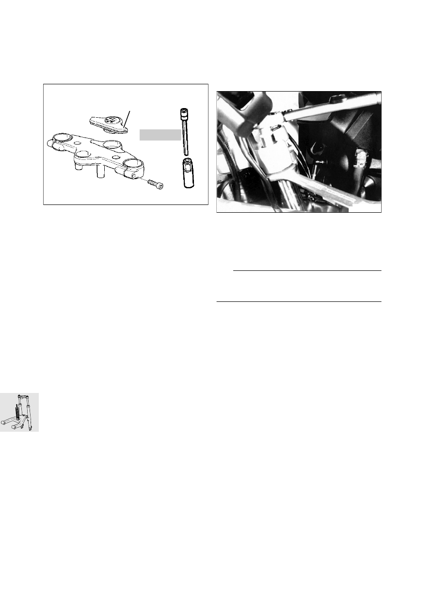
[RS] Removing and installing fork 
bridge

Separate connecting plug for ignition/steering 
lock. 

Unscrew handlebar mount on fork bridge.

Remove trim (1).

Heat ball joint mount on fork bridge to max. 
120 °C and unscrew using Allen key socket 
wrench insert, BMW No. 31 5 600.

Unscrew fixed tube clamp mount at top of fork 
bridge.

Remove fork bridge.

Remove ignition/steering lock.

Install in the reverse order of work.

Projection of fixed tube beyond fork bridge:

................................ 5 

± 0.5

 mm (0.1969

± 0.01969 

in)

X

 Tightening torque:

Mount, fixed tube/fork bridge ....................... 22 Nm
Ball joint at fork bridge 
(clean thread + Loctite 2701)...................... 130 Nm

[GS/R/RT] Removing and installing 
fork bridge

Unscrew fuel tank and pull to the rear.

Separate connecting plug for ignition/steering 
lock. 

Detach handlebar from fork bridge.

Unfasten fixed tube screw connection at fork 
bridge, preventing movement by holding hexa-
gon on fixed tube.

Unfasten screw connection between fork bridge 
and frame.

L

 Note:

Screw pin is a press fit in ball thrust bearing: remove 
complete unit.

[R] Scheinwerferhalterung nach vorne ziehen.

Gabelbrücke abnehmen.

Zündlenkschloß ausbauen.

Einbau in umgekehrter Reihenfolge.

X

 Tightening torque:

Screw connection between fork bridge and frame
(clean thread + Loctite 243)........................ 130 Nm
Threaded connection between fork bridge and fixed 
tube (free from oil and grease)...................... 45 Nm
Handlebar to fork bridge .............................. 21 Nm

GS310030

31 5 600

1

j

120

w

GS000410

31.9

Removing and installing pot-type joints

Remove dust covers (1).

Remove top snap ring (2).

Press out pot-type joint using drift and bushing, 
BMW No. 31 5 660.

Snap ring (3) is installed.

Press in pot-type joint using drift, 
BMW No. 31 5 661.

Install snap ring (2).

Install dust covers (1).

31 5 661

31 5 662

1

1

2

GS310080

31 5 661

1

2

1

3

GS310090

31.10

Removing and installing ball thrust bearing

Remove retaining ring (1).

Heat fork bridge to 100 °C.

Remove ball thrust bearing, if necessary striking 
lightly with a plastic-faced hammer.

Press out the threaded journal using a pin, 
BMW No. 31 5 651, as a support.

Press the threaded journal into the ball thrust 
bearing using a pin, BMW No. 31 5 651, as a 
support.

Heat the fork bridge to 100 °C and press the ball 
thrust bearing in with pin, BMW No. 31 5 651 and 
bushing, BMW No. 31 5 653.

Install retaining ring.

1

j

100

w

GS310100

31 5 651

GS310110

31 5 651

GS310120

31 5 651

31 5 653

j

100

w

GS310130

31.11

Removing and installing slider tube 
bridge

Remove front mudguard.

Heat ball joint mount at slider tube bridge to max. 
120 °C and detach it.

[R] Heat the steering damper mount at the slider 
tube bridge to max. 120 °C and detach it..

[RS/GS] Detach the brake line distributor block.

[ABS] Detach the sensor line from the slider tube 
bridge.

Unscrew slider tube bridge.

Install in the reverse order of work.

Secure the ball joint to the leading link using 
socket wrench insert and Allen key, 
BMW No. 31 5 600.

e

 Caution:

Comply with assembly instructions for telescopic 
fork.

X

 Tightening torque:

Bridge to fork slider 
(clean thread + Loctite 243).......................... 22 Nm
Ball joint on control arm 
(clean thread + Loctite 2701)...................... 130 Nm

Removing and installing ball joint

Mount the slider tube bridge in retaining fixture, 
BMW No. 31 5 620.

Unscrew/tighten ball joint with 46 mm (1.811in) 
socket wrench insert, BMW No. 31 5 630.

X

 Tightening torque:

Ball joint to fork slider bridge ...................... 230 Nm

[RS] Checking ball joint friction

[GS/R/RT] Checking ball joint/ball 
thrust bearing friction

Motorcycle must be supported on center stand 
with front wheel clear of the ground.

Measure the breakaway torque to left and right 
from the central position of the handlebar with 
friction gauge, BMW No. 00 2 57

L

 Note:

To determine the friction value, increase torque very 
slowly.

Friction value:
Measure at room temperature (above 20 °C)
Nominal value: .................................... 1.0...4.0 Nm

v

243

j

120

w

v

2701

GS310040

31.12

Assembly specification for telescopic fork:

e

 Caution:

To ensure that the fork is installed without trapped 
stresses, observe the following instructions and the 
specified working sequence precisely.

The front suspension strut is removed.

e

 Caution:

Protect painted parts from scratching: apply adhe-
sive masking tape if necessary.

Bolt fork bridge to frame.

X

 Tightening torque:

Fork bridge to ball joint
(clean thread + Loctite 2701)
[RS] .......................................................... 130 Nm
Threaded journal to frame
(clean thread + Loctite 243)
[GS/R/RT] ................................................. 130 Nm

Pre-assemble fork legs with quick-release axle/
adjust distance A.

Distance A:.............165 

± 

0.5

 mm (6.496

± 0.01969 

in)

X

 Tightening torque::

Quick-release axle clamps ........................... 22 Nm

L

 Note:

If the quick-release axle was not removed, for in-
stance when only the fork slider tube bridge was re-
moved/installed, the above work stage is omitted.

Secure slider tube bridge/do not tighten to spec-
ified torque at this point.

Screw slider tube bridge to leading link.

X

 Tightening torque:

Leading link at ball joint 
(clean thread + Loctite 2701)...................... 130 Nm

Using a strap or similar, pull fork towards frame 
until the fully retracted fixed tubes only need to 
be pulled out slightly to secure them to the fork 
bridge. Secure fixed tubes to the fork bridge.

Secure fixed tubes to the fork bridge.

X

 Tightening torque:

Clamp between fixed tubes and fork bridge
[RS] ............................................................. 22 Nm
Screw connection between fixed tube and fork 
bridge (oil/grease free) 
[GS/R/RT].................................................... 45 Nm

Tighten down slider tube bridge.

X

 Tightening torque:

Bridge to fork slider (clean thread + 
Loctite 243) .................................................. 22 Nm

Check that the system moves freely by com-
pressing and extending the suspension (but 
without the suspension strut) in the straight-
ahead and left/right steering lock positions.

Remove quick-release axle.

e

 Caution:

When being reassembled, the quick-release axle 
must well aligned; it should be possible to install it 
by rotating it slightly.

Install suspension strut.

X

 Tightening torque::

Spring strut to frame .................................... 47 Nm
Spring strut to leading link
[RS] (8.8 bolt)............................................... 43 Nm
[RS] (10.9 bolt)............................................. 50 Nm
[GS/R/RT] (10.9 bolt) ................................... 50 Nm

A

GS310140

31.13

Dismantling/reassembling 
telescopic fork

Dismantling telescopic fork

Remove bleed screw (1).

Remove drain plug (2)/drain oil.

Remove fixed tube.

Remove dust cover (3)/retaining ring (4).

Lever out shaft seal (5)

e

 Caution:

Do not damage fork slider tube.

Remove washer (6).

1

2

3

4

5

6

7

GS/R/RT

RS

1

GS310050

31.14

Assembling telescopic fork

Insert oil drain plug.

e

 Caution:

Install a new O-ring (7). Make sure the O-ring is cor-
rectly seated.

Fill with oil.

Fill quantity per fixed tube:
[RS/GS/R/RT]
 .................0.470 l (0.827 Imp. pints)

Oil grade in telescopic fork:

..........................................BMW telescopic fork oil

L

 Note:

No oil changes required during services: unit is 
maintenance-free.

Install fixed tube.

Install washer (6).

Oil the shaft seal slightly and push it on as far as 
possible (to stop on slider tube) by striking it 
lightly with drift, BMW No. 31 5 610, and reduc-
ing adapter, BMW No. 31 5 613.

Install retaining ring and dust cover.

Insert bleed screw (1).

Bleed telescopic fork in no-load position.

X

 Tightening torque:

[RS] Threaded plug at fixed tube ................. 18 Nm
[GS/R/RT] Threaded plug at fixed tube

....................................... press-fit - do not remove!

Measuring telescopic fork

e

 Caution:

After an accident, always examine the telescopic 
fork for cracks and signs of damage.

Check slider tube bridge

Check that the slider tube bridge is flat. 

e

 Caution:

Renew slider tube bridge if distorted.

Checking runout of fixed tube

Place both ends of fixed tube in V-blocks.

Rotate fixed tube slowly and check with dial 
gauge while doing so.

e

 Caution:

Do not straighten distorted fixed tubes: 
always renew them.

Permissible runout: ................. 0.4 mm (0.0157 in)

RS310061

31.15

Removing and installing leading link

[RT] Remove side sections of fairing.

[R] Detach steering damper mount at leading 
link.

Unscrew bottom of spring strut.

Heat ball joint mount (1) at leading link to max. 
120 °C and detach it.

Remove covers (2) from leading link pivots.

Remove left screw cap (3).

Remove right retaining ring (4) and retaining 
cap (5).

Take out right screw (6) and remove shaft (7) by 
pulling to the left.

Pull telescopic fork forwards and carefully re-
move leading link by pulling forwards.

e

 Caution:

Protect painted parts from scratching: apply 
adhesive masking tape if necessary

Install in the reverse order of work.

Apply a light coating of grease to the axle before 
installing.

Using socket wrench insert and Allen key, 
BMW No. 31 5 600, tighten the ball joint at the 
leading link.

[RS] Coat the lower suspension strut mount with 
Never Seez.

L

 Note:

Only applies to plain bearings

X

 Tightening torque:

Right control arm on engine ......................... 73 Nm
Left screw cap (coat thread lightly with
Never Seez).................................................. 42 Nm
Leading link to ball joint
(clean thread + Loctite 2701)...................... 130 Nm
Spring strut to leading link
[RS] (8.8 bolt)............................................... 43 Nm
[RS] (10.9 bolt)............................................. 50 Nm
[GS/R/RT] (10.9 bolt) ................................... 50 Nm
Steering damper mount to leading link
[R]................................................................ 20 Nm

Dismantling/reassembling leading 
link

Press bearing out/in using suitable tool.

e

 Caution:

Always install bearing by applying pressure to 
outer race.

31 5 600

2

3

7

6

5

4

2

j

120

w

v

2701

1

RS310010


Content   ..  29  30  31  32   ..