BMW AG Motorcycle (R 850 C, R 1200 C). Manual - part 22
 

  Index      Manuals     BMW AG Motorcycle (R 850 C, R 1200 C). Repair Manual


Search            


Content   ..  20  21  22  23   ..


BMW AG Motorcycle (R 850 C, R 1200 C). Manual - part 22


33.14

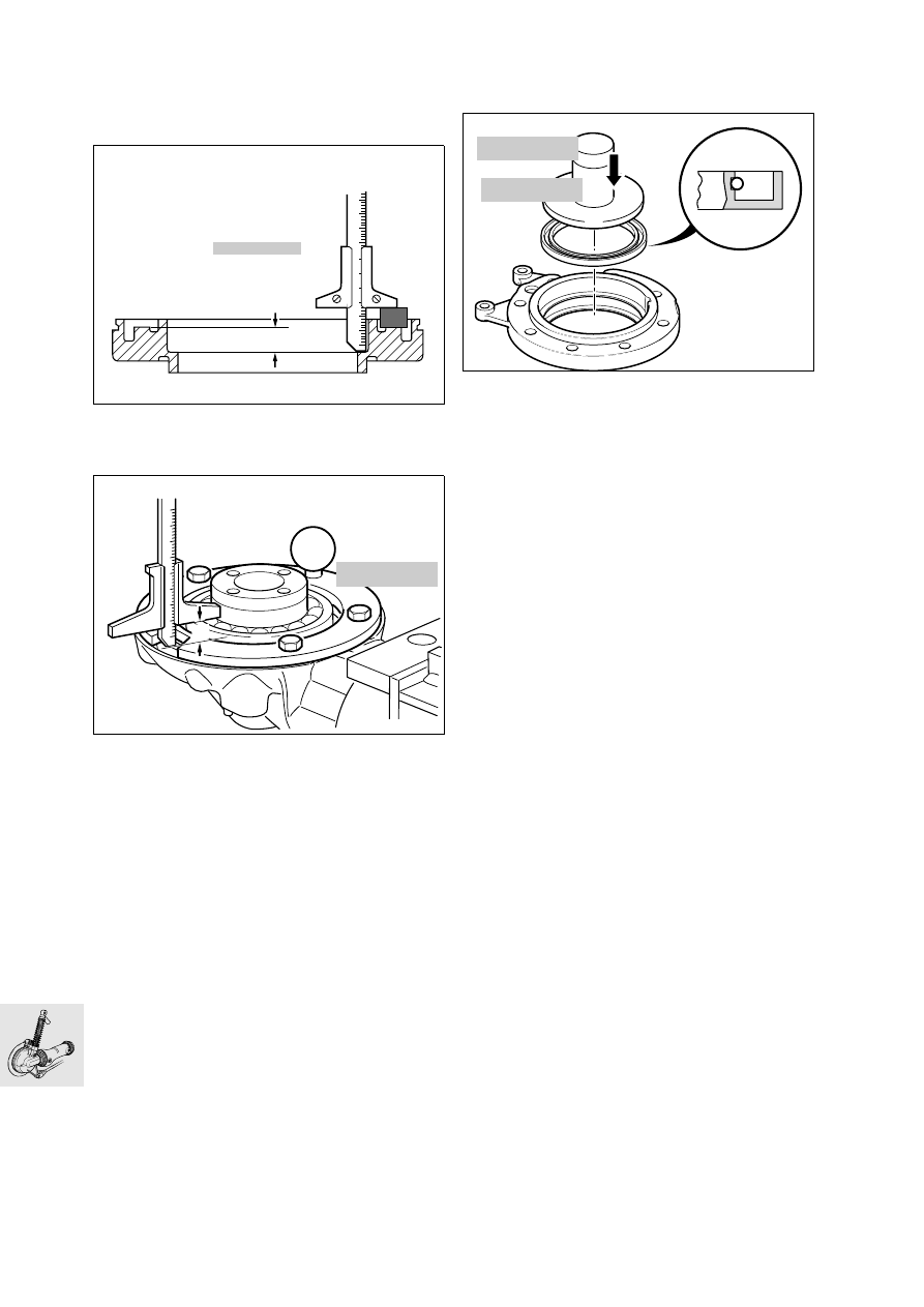
Shimming housing cover

To obtain the correct roller bearing preload, the 
housing cover must be shimmed. 

Using depth gauge, BMW No. 00 2 550, meas-
ure distance a.

Place measuring ring, BMW No. 33 2 601, in po-
sition and secure it.

Measure from the outer ball bearing race through 
the cutout in the measuring ring to the housing 
joint face and determine distance b.

Distance a – distance b = shim thickness (without 
preload).

Apply a light coat of grease to the selected shim 
washer, and install it.

Preload:............ 0.05...0.1 mm (0.0020...0.0039 in)

Installing housing cover

Lightly oil the lip and outer edge of the sealing 
ring.

Using drift, BMW No. 33 1 870, and handle, 
BMW No. 00 5 500, drive in the sealing ring.

Install O-ring and apply a light coat of oil/grease.

Heat housing cover to 80 °C (176 °F)/install. 

Tighten retaining bolts in a crosswise pattern.

Tightening torque:

Housing cover.............................................. 35 Nm

Installing splined element

Coat splines on input pinion with Staburags 
NBU 30 PTM
.

Fit sliding element to drive pinion.

Locate retaining ring with gentle blows (plastic 
hammer).

a

00 2 550

KR330290

b

33 2 601

C330080

C330120

33 1 870

00 5 500

33.15

Removing/installing rear swinging 
fork

Removing rear swinging arm

Detach the lower suspension strut mount (1)

.

Force off the left swinging arm bearing cap using 
two screwdrivers in the holes.

Loosen the free swinging arm bearing journal.

Detach the fixed swinging arm bearing journal.

Using pull rod, BMW No. 00 8 581, and impact 
weight, BMW No. 00 8 582, pull out the fixed 
swinging arm bearing journal.

Remove the swinging arm bearing journal.

A

A

C330014

C330030

00 8 581

C330040

00 8 582

33.16

Removing and installing taper roller 
bearing

Pull the taper roller bearing out with counter-sup-
port, BMW No. 00 8 572, and internal puller
21/2, BMW No. 00 8 571.

Pull out outer race with internal puller 21/5, 
BMW No. 00 8 563.

To install the bearing, heat the swinging arm to 
80 °C (176 °F).

Bearing with drift, BMW No. 33 5 700 

Removing and installing flexible gaiter

Pull flexible gaiter with circlip out of swinging 
arm.

When installing, coat inner and outer sealing lips 
(arrows) with Staburags NBU 30 PTM.

e

 Caution:

Drive shaft clearance when suspension is com-
pressed: 
aperture in retaining ring must be horizontal.

Removing drive shaft

Press off drive shaft.

e

 Caution:

Avoid scratching painted parts; use an underlay if 
necessary.

Checking universal joint for wear

Determine end float and face runout.

Installing drive shaft

Coat the splines on the output shaft with 
Staburags NBU 30 PTM.

Fit drive shaft to output shaft.

Engage the snap ring with gentle blows (plastic 
hammer).

LT330370

00 8 563

00 8 571

00 8 572

KR330340

C330050

KR330360

33.17

Installing rear swinging arm

Slide swinging arm over drive shaft as far as pos-
sible until rubber gaiter connects on housing 
neck.

Install fixed bearing journal (1).

Screw in free bearing journal (2).

Tighten fixed bearing journal.

Tighten free bearing journal.

Tighten locknut (3).

Install the left swinging arm bearing cap.

e

 Caution:

Make sure that the O-ring is in good condition.
The drain hole must point down.

Secure suspension strut (1).

Tightening torque:

Fixed bearing journal .................................... 10 Nm
Free bearing journal  ...................................... 7 Nm
Locknut ...................................................... 160 Nm
Suspension strut to swinging arm ................ 50 Nm

A

A

C330014

2

3

1

33.18

Installing rear wheel drive

Coat splines at sliding element (arrow) with 
Staburags NBU 30 PTM.

Offer up the rear wheel drive assembly and guide 
the sliding element into the drive shaft.

Tightening torque:

Rear wheel drive to swinging arm................  21 Nm

If necessary, fill with oil.

Fill quantity:
(up to lower edge of thread on oil filler plug)
Initial 
filling ...........app. 0.20 l (0.35 Imp. pint/0.21 US quart)
During oil 
changes .....app. 0.18 l (0.32 Imp. pint/0.19 US quart)

Oil grade:
Brand-name hypoid gear oil, SAE 90, API class GL 5

[ABS] Install the brake disc in the previously 
marked position.

Install the rear wheel.

Install brake caliper

e

 Caution:

Do not damage brake pads; do not tilt when install-
ing.

Install speedometer signal transmitter.

[ABS] Install sensor.

[ABS] Check that sensor gap is correct.

ABS rear
sensor gap: 
........ 0.50...0.55 mm (0.019...0.021 in)

C330011

33.19

Removing and installing 
suspension strut

L

 Note:

To remove the suspension strut, support the rear 
axle.

Tightening torque:

Suspension 
strut to swinging arm/rear frame................... 50 Nm

33.20

34.1

Contents

Page

34

Technical data 

................................................................................................................................3

Removing and installing front brake caliper 

.................................................................5

Dismantling and assembling front brake caliper 

........................................................6

Dismantling front brake caliper

 .................................................................................................6

Assembling front brake caliper

 .................................................................................................6

Removing and installing rear brake caliper 

...................................................................7

Dismantling and assembling rear brake caliper 

.........................................................8

Dismantling rear brake caliper

 ..................................................................................................8

Assembling rear brake caliper

 ..................................................................................................8

Removing and installing front brake disc 

.......................................................................9

Removing/installing rear brake disc 

................................................................................10

Removing and installing front ABS sensor 

..................................................................11

Adjusting front ABS sensor gap 

.........................................................................................12

Marking sensor wheel

 .................................................................................................................12

Checking and adjusting sensor gap

 .....................................................................................12

Removing and installing rear ABS sensor 

....................................................................13

Adjusting rear ABS sensor gap 

..........................................................................................14

Marking sensor wheel

 .................................................................................................................14

Checking and adjusting sensor gap

 .....................................................................................14

Removing and installing rear brake master cylinder 

..............................................15

Checking and adjusting reliefclearance of piston rod

 ..................................................15

Removing and installing brake pedal 

..............................................................................15

Removing and installing ABS unit 

.....................................................................................16

34 Brakes


Content   ..  20  21  22  23   ..