BMW AG Motorcycle (R 850 C, R 1200 C). Manual - part 19


  Index      Manuals     BMW AG Motorcycle (R 850 C, R 1200 C). Repair Manual


Search            


Content   ..  17  18  19  20   ..


BMW AG Motorcycle (R 850 C, R 1200 C). Manual - part 19


31.6

Install by following the above work instructions in 
the reverse order.

Using a socket wrench insert and internal hexa-
gon, BMW No. 31 5 600, tighten the ball joint at 
the leading link.

e

 Caution:

To prevent grease from escaping and the ingress of 
dirt, ensure that sleeve is correctly located on ball 
joint.

[ABS] Check sensor gap and adjust if necessary.

ABS – 
Sensor gap:
........ 0.50...0.55 mm (0.019...0.021 in)

Tightening torque:

Screw connection between fork bridge and frame
(clean thread + Loctite 243)........................ 130 Nm
Threaded connection between fork bridge and fixed 
tube (free from oil and grease) ...................... 35 Nm
Handlebar at fork bridge
(install the lower clamping block facing forwards
(direction of arrow) and tighten the front clamp first)

.................................................................... 21 Nm

Instrument holder at fork bridge ..................... 9 Nm
Headlight holder at fork bridge ..................... 15 Nm

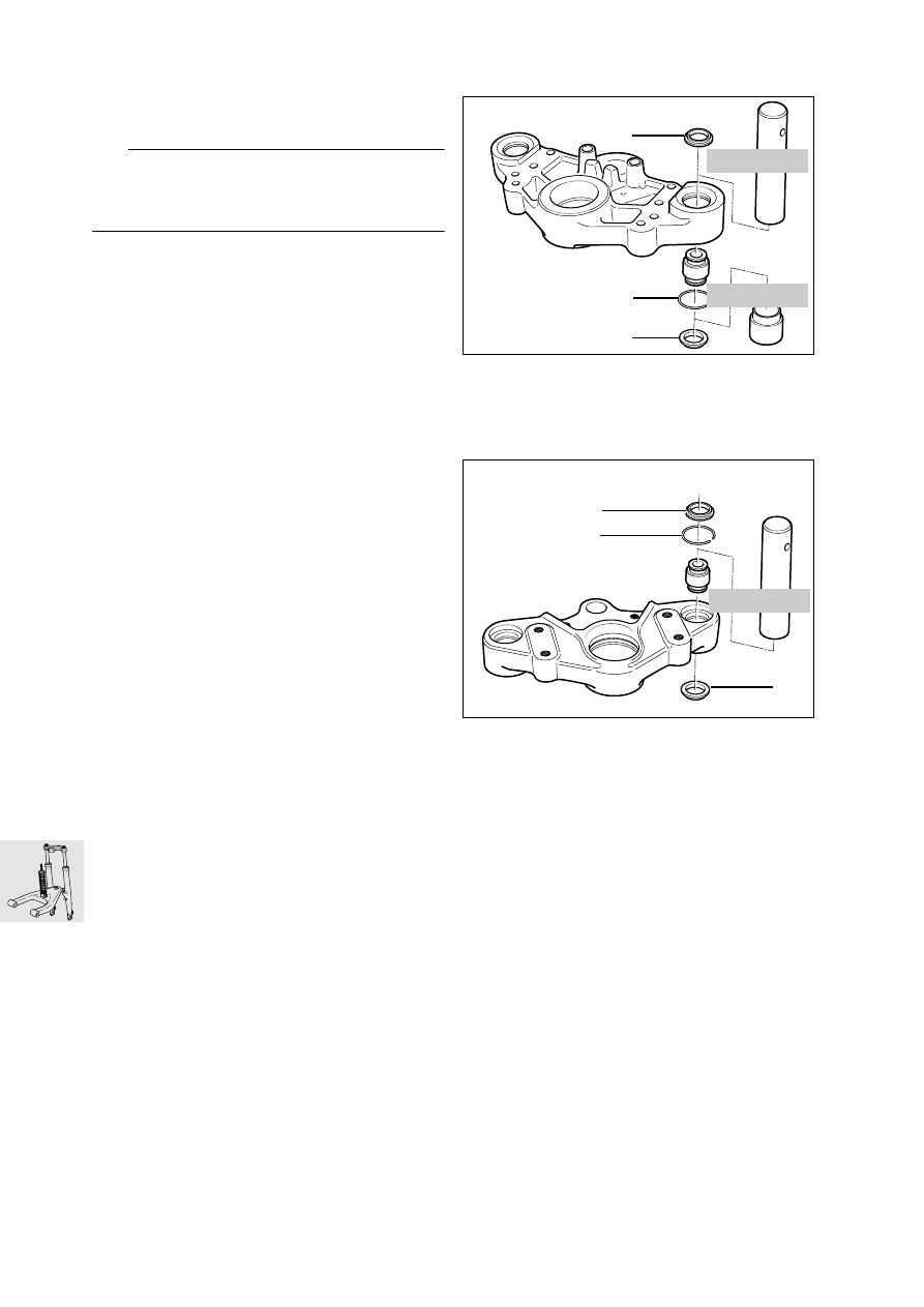
Removing and installing pot-type joints

Remove dust covers (1).

Remove snap ring (2).

Press out pot-type joint with pin, 
BMW No. 31 5 661, and bushing, 
BMW No. 31 5 662.

Press the pot-type joint in with pin,
BMW No. 31 5 661.

Install snap ring (2).

Install dust covers (1).

31 5 661

31 5 662

1

2

1

31 5 661

C310040

1

1

2

31.7

Removing and installing ball thrust bearing

Remove retaining ring (1).

Heat fork bridge to 100 °C (212 °F).

Remove ball thrust bearing, if necessary striking 
lightly with a plastic-faced hammer.

Press out the threaded journal using a pin,
BMW No. 31 5 651, as a support.

Press the threaded journal into the ball thrust 
bearing using a pin, BMW No. 31 5 651, as a 
support.

Heat the fork bridge to 100 °C (212 °F) and press 
in the ball thrust bearing with pin, 
BMW No. 31 5 651, and bushing,
BMW No. 31 5 653.

Install retaining ring.

C310050

1

GS310110

31 5 651

GS310120

31 5 651

31 5 651

C310060

31 5 653

31.8

Removing and installing slider tube 
bridge

Removing the front mudguard

Heat the ball joint mount on the leading link to 
max. 120 °C (248 °F) and detach it.

Unscrew slider tube bridge.

Install by following the above work instructions in 
the reverse order.

Tighten the ball joint to the leading link using 
socket wrench insert and internal hexagon, 
BMW No. 31 5 600.

e

 Caution:

Comply with assembly instructions for telescopic 
fork.

Tightening torque:

Bridge to fork slider
(clean thread + Loctite 243).......................... 22 Nm
Ball joint to leading link 
(use a new nut or clean 
thread + Loctite 2701) ................................ 130 Nm

Removing and installing ball joint

Mount the slider tube bridge in retaining fixture, 
BMW No. 31 5 620.

Unscrew/tighten ball joint with 46 mm (1.81 in) 
socket wrench insert, BMW No. 31 5 630, in 
conjunction with protective ring, 
BMW No. 31 5 632.

Tightening torque:

Ball joint to slider tube bridge
(apply Never Seez to thread) ...................... 230 Nm

Checking friction at ball joint/ball 
thrust bearing

Motorcycle raised on auxiliary stand,
BMW No. 00 1 550; front wheel must be clear of 
ground.

Measure the breakaway moment to left and right 
from the central position of the handlebar using 
friction meter, BMW No. 00 2 570

L

 Note:

To determine the friction value, increase torque very 
slowly.

Friction value:
Measure at room temperature (above 20 °C/68 °F) 
Nominal value: .................................... 1.0...4.0 Nm

C310021

31.9

Assembly specification for telescopic fork:

e

 Caution:

To ensure that the fork is installed without trapped 
stresses, observe the following instructions and the 
specified working sequence precisely.

The front suspension strut is removed.

e

 Caution:

Protect painted parts from scratching: apply adhe-
sive masking tape if necessary.

Bolt fork bridge to frame.

Tightening torque:

Threaded journal to frame
(clean thread + Loctite 243)........................ 130 Nm

Pre-assemble fork legs with quick-release axle/
adjust distance A.

Distance A:................... 165 

± 0.5

 mm (6.50 

±0.02

 in)

Tightening torque:

Quick-release axle clamps ........................... 22 Nm

L

 Note:

If the quick-release axle was not removed, for in-
stance when only the fork slider tube bridge was re-
moved/installed, the above work stage is omitted.

Secure slider tube bridge/do not tighten to spec-
ified torque at this point.

Screw slider tube bridge to leading link.

Tightening torque:

Leading link at ball joint
(clean thread + Loctite 2701)...................... 130 Nm

Using a strap or similar, pull fork towards frame 
until the fully retracted fixed tubes only need to 
be pulled out slightly to secure them to the fork 
bridge.  

Secure fixed tubes to the fork bridge.

Tightening torque:

Screw connection between fixed tube and fork 
bridge (free from oil and grease)  .................. 35 Nm

Tighten down slider tube bridge.

Tightening torque:

Bridge to fork slider
(clean thread + Loctite 243).......................... 22 Nm

Check that the system moves freely by com-
pressing and extending the suspension (but 
without the suspension strut) in the straight-
ahead and left/right steering lock positions.

Remove quick-release axle.

e

 Caution:

When being reassembled, the quick-release axle 
must well aligned; it should be possible to install it 
by rotating it slightly.

Install suspension strut.

Tightening torque:

Spring strut to frame .................................... 40 Nm
Spring strut to leading link............................ 40 Nm

GS310140

A

31.10

Dismantling/reassembling
telescopic fork

Dismantling telescopic fork

Remove bleed screw (1).

Pull out fixed tube/drain oil.

Carefully press off chromium plated cap (2) at 
groove.

Lever out the dust sleeve (3).

e

 Caution:

Do not damage fork slider tube.

Remove retaining ring (4).

Lever out shaft seal (5).

Remove washer (6).

Assembling telescopic fork

Fill with oil.

Qualtity per 
fixed tube 
.... 0.470 l (0.82 Imp. pint/0.49 US quart)

Oil grade
in telescopic fork:
............. BMW telescopic fork oil

L

 Note:

No oil changes required during services: unit is 
maintenance-free.

Install fixed tube.

Install washer (6).

Oil the shaft seal slightly and push it on as far as 
possible (to stop on slider tube) by striking it 
lightly with drift, BMW No. 31 5 610, and reduc-
ing adapter, BMW No. 31 5 613.

Install retaining ring and dust cover.

Attach the chromium plated cap.

Insert bleed screw (1).

Bleed telescopic fork in no-load position.

Tightening torque:

Screw plug to
fixed fork tube ................. press-fit - do not remove!

C310010

2

1

3

4

5

6

31.11

Measuring telescopic fork

e

 Caution:

After an accident, always examine the telescopic 
fork for cracks and signs of damage.

Check slider tube bridge

Check that the slider tube bridge is flat. 

e

 Caution:

Renew slider tube bridge if distorted.

Checking runout of fixed tube

Place both ends of fixed tube in V-blocks.

Rotate fixed tube slowly and check with dial 
gauge while doing so.

e

 Caution:

Do not straighten distorted fixed tubes: always re-
new them.

Permissible runout: ................... 0.4 mm (0.016 in)

RS310060

31.12

Removing and installing leading link

Unscrew bottom of spring strut.

Heat ball joint mount (1) at leading link to max. 
120 °C (248 °F) and detach it.

Remove covers (2) from leading link pivots.

Remove left screw cap (3).

Remove right retaining ring (4) and retaining
cap (5).

Take out right screw (6) and remove shaft (7) by 
pulling to the left.

Pull telescopic fork forwards and carefully re-
move leading link by pulling forwards.

e

 Caution:

Protect parts against scratching; mask them off if 
necessary.

Install by following the above work instructions in 
the reverse order.

Apply a light coating of grease to the axle before 
installing.

Tighten the ball joint at the leading link with the 
socket wrench insert and internal hexagon, 
BMW No. 31 5 600.

Tightening torque:

Right leading link to engine .......................... 73 Nm
Left screw cap 
(coat thread lightly with Never Seez)............. 42 Nm
Leading link to ball joint
(use a new nut or clean
thread + Loctite 2701) ................................ 130 Nm
Spring strut to leading link............................ 40 Nm

Dismantling/reassembling leading 
link

Press the bearing out/in with a suitable drift.

e

 Caution:

Always install bearing by applying pressure to outer 
race.

Removing and installing front 
suspension strut

Detach and pull back the fuel tank.

e

 Caution:

Protect parts against scratching; mask off if neces-
sary.

Tightening torque:

Spring strut to frame .................................... 40 Nm
Spring strut to leading link............................ 40 Nm

1

31 5 600

C110041

4

5

6

7

3

2

2

32.1

Contents

Page

32

Technical data 

................................................................................................................................3

Removing and installing left handlebar fitting 

.............................................................5

Removing and installing right handlebar fitting 

..........................................................6

Removing and installing handlebar 

....................................................................................7

Removing/installing throttle cable 

......................................................................................8

32 Steering


Content   ..  17  18  19  20   ..