BMW AG Motorcycle (R 850 C, R 1200 C). Manual - part 16


  Index      Manuals     BMW AG Motorcycle (R 850 C, R 1200 C). Repair Manual


Search            


Content   ..  14  15  16  17   ..


BMW AG Motorcycle (R 850 C, R 1200 C). Manual - part 16


23.6

Separate the side (prop) stand swithc plug.

Separate the neutral indicator plug.

Detach the left plug holder plate.

Remove the injectors.

Pull the plugs off the injector lines.

Disconnect the brake light switch plug and de-
tach the cable.

Detach the breather hose at the air cleaner cas-
ing.

Detach the throttle cable at the twistgrip. 

Remove rear section of frame.

Detach the footrest assembly.

Remove the starter motor cover.

Detach the positive lead from the starter motor.

Remove the battery.

Unscrew rear battery mount.

Raise the battery holder at the rubber mount.

Detach the clutch slave cylinder mount and pull 
out of the gearbox.

Pull out the thrust rod.

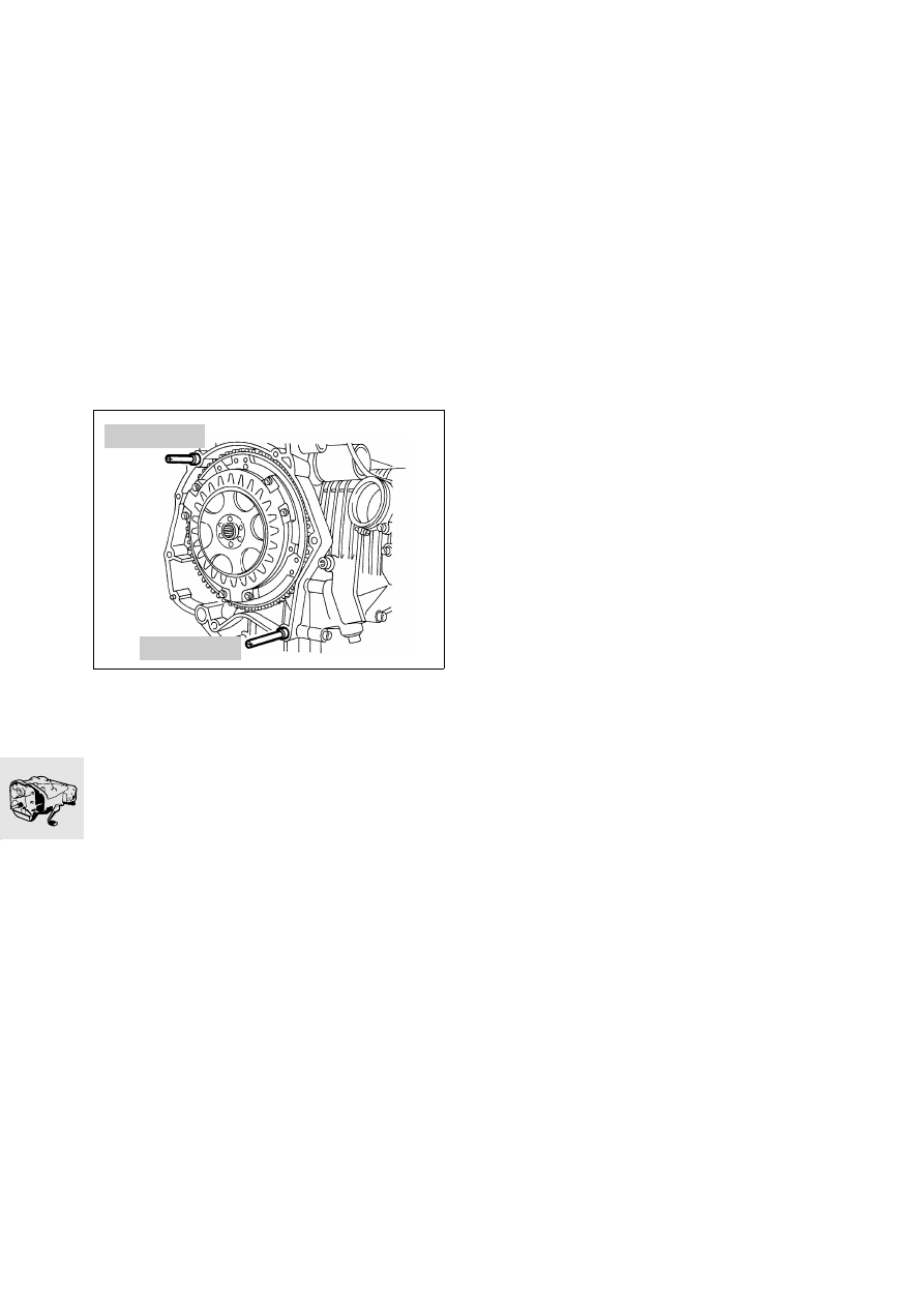
Detaching the gearbox

When removing, pull the gearbox out on guide 
pins, BMW No. 23 1 820.

Install by following the above work instructions in 
the reverse order.

23 1 820

RS230010

23 1 820

23.7

Renewing the shaft sealing rings in the 
gearbox housing and gearbox cover

L

 Note:

All shaft sealing rings can be renewed with the gear-
box installed, apart from the input-side shaft sealing 
ring on the input shaft.
If the gearbox is dismantled completely, all shaft 
sealing rings must be renewed.
Before installing shaft sealing rings, oil their sealing 
lips lightly.

Renew the input shaft sealing ring at the input 
end

Lever the shaft sealing ring out with a screw-
driver.

Drive the new sealing ring in with the sealing lips 
facing inwards, using slip-over sleeve, 
BMW No. 23 4 712, and drift, 
BMW No. 23 7 711.

Renewing output shaft sealing ring

e

 Caution:

Never use a sharp tool to remove the output shaft 
sealing ring, or the plastic washer on the deep-
groove ball bearing behind the shaft sealing ring 
could be damaged.

Pull the shaft sealing ring out with puller, 
BMW No. 00 8 590.

Install the sealing ring with the sealing lips facing 
inwards, using slip-over sleeve, 
BMW No. 23 4 732, and drift, 
BMW No. 23 4 731.

23 4 712

C330150

23 4 711

00 8 590

23 4 732

23 4 731

23.8

Renewing input shaft sealing ring at output side

Pierce the shaft sealing ring with piercing tool, 
BMW No. 00 8 583.

Screw the pull rod, BMW No. 00 8 581, into the 
pierced hole and use impact weight, 
BMW No. 00 8 582, to remove the shaft sealing 
ring.

Install the new sealing ring with the sealing lips 
facing inwards, using guide pin, 
BMW No. 23 4 722, and impact driver, 
BMW No. 23 4 721
.

Renewing shaft sealing ring for selector drum

Lever the shaft sealing ring out with a screw-
driver.

Install the new sealing ring with the sealing lips 
facing inwards, using impact driver, 
BMW No. 23 4 750.

Renewing sealing ring for selector shaft

Lever the shaft sealing ring out with a screw-
driver. 

Install the new sealing ring with the sealing lips 
facing inwards, using slip-over sleeve, 
BMW No. 23 4 612, and impact driver, 
BMW No. 23 4 740.

C230160

23 4 612

23 4 740

23 4 750

00 8 581

23 4 721

23 4 722

00 8 583

00 8 582

23.9

Dismantling gearbox

Removing gearbox housing

Take out oil filler/level check screw (2).

Take out oil drain plug (7) and drain the oil out of 
the gearbox into a suitable tray.

Remove breather (1).

Unclip cable (3) for neutral indicating switch (4).

Compress spring (5) and take off neutral indicat-
ing switch (4).

Remove selector lever (6).

Carefully press back centering pins (arrows), 
working from the back of the gearbox.

Remove screws (8) securing cover to housing.

Set the gearbox down on its cover.

e

 Caution:

Avoid damage to the housing cover and painted sur-
faces.

Heat the bearing points in the housing to
80 °C... 100 °C (176 °F...212 °F).

Strike lightly with a plastic-faced hammer to re-
lease the gearbox. 

C230012

1

4

7

6

5

3

8

2

C230020

h

80…100

w

23.10

Removing selector drum

Pull the selector shafts (1) out of the selector 
forks.

Swing the selector forks (3/8) out towards the 
edge of the cover (arrows).

Remove locking pin (9).

Press guide plate (5) in the opposite direction to 
the spring loading (arrow).

Swing locking lever (6) towards input shaft (7), 
hold it there and pull out the selector drum (4), 
turning it slightly at the same time.

Remove the thrust washers and spacing washer.

Release the locking lever (6).

Remove the selector shaft (7) with spacing wash-
er.

Remove selector forks (3).

Selector fork (8) remains in the intermediate 
shaft (10). 

Dismantling/assembling selector shaft

Remove torsion spring (5) with locking lever (4) 
from selector shaft (2).

Remove torsion spring (1).

Remove coil spring (6) and take off together with 
sliding plate (3).

Assemble in the opposite order of work.

C230030

1

7

9

10

1

8

5

3

6

4

2

KR230050

1

2

3

4

5

6

23.11

Removing gearbox shafts

Remove breather tube (3).

Heat bearing points in gearbox cover to
80 °C … 100 °C (176 °F ... 212 °F).

Take off input shaft (4), output shaft (1) and 
intermediate shaft (5) together from the cover.

Remove selector fork (2) from intermediate shaft.

Renewing deep-groove ball bearing 
on intermediate shaft 

e

 Caution:

If the deep-groove ball bearings are renewed, the 
fully-compressed length must be re-adjusted.

Pull off the deep-groove ball bearings with a uni-
versal puller, BMW No. 00 7 500.

Press the output-side deep-groove ball bearing 
on to the intermediate shaft.

Check/adjust fully-compressed length
(

23.17).

Place the spacing washer of the determined 
thickness in position and press on the input-side 
deep-groove ball bearing.

C230040

1

4

5

h

80…100

w

2

3

00 7 500

KR230070

23.12

Dismantling/assembling input shaft

Dismantling input shaft

Clamp the input shaft into the vise, using soft 
jaws.

Use universal puller, BMW No. 00 7 500, and 
pressure head (arrow) to pull off deep-groove ball 
bearing (9) with spacing washer (8).

Note the thickness of spacing washer (8).

Remove guide ring (7).

Compress spring cluster (4) and remove split 
segment washer (6).

Remove support disc (5), spring cluster (4), anti-
rattle disc (3), thrust block (2) and constant-
speed gear (1).

Transfer input shaft (10) to a different position.

Use universal puller, BMW No. 00 7 500, and 
pressure head (arrow) to pull off deep-groove ball 
bearing (11).

11

10

KR230080

9

8

7

6

5

4

3

2

1

00 7 500

KR230090

9

23.13

Assembling input shaft

Oil the bearing surface for constant-speed 
gear (1) lightly on input shaft (10), and install the 
constant-speed gear.

Oil the splines in thrust block (2) lightly and install 
it.

Place anti-rattle disc (3) on thrust block (2).

Mount spring cluster (4) and circlip (arrow) facing 
upwards on anti-rattle disc (3).

Install a support disc (5) of the same thickness as 
the one previously removed.

Compress spring cluster (4) and insert the split 
segment washer (6) in the ring groove.

Install guide ring (7) with shoulder facing over 
segment disc (6).

Check fuly-compressed length and adjust if nec-
essary (

23.19).

Install spacing washer (8) of the determined 
thickness, and press on deep-groove ball bear-
ing (9).

Check endplay of spring cluster (4).

L

 Note:

If endplay is greater than the tolerance limit, the 
cause may be wear or incorrect assembly.

Endplay:
Spring
cluster on shaft  ...... 0.4…0.6 mm (0.016…0.024 in)

11

10

KR230080

9

8

7

6

5

4

3

2

1


Content   ..  14  15  16  17   ..