BMW AG Motorcycle (K1100LT, K1100RS). Manual - part 23
 

  Index      Manuals     BMW AG Motorcycle (K1100LT, K1100RS). Repair Manual


Search            


Content   ..  21  22  23  24   ..


BMW AG Motorcycle (K1100LT, K1100RS). Manual - part 23


23.13

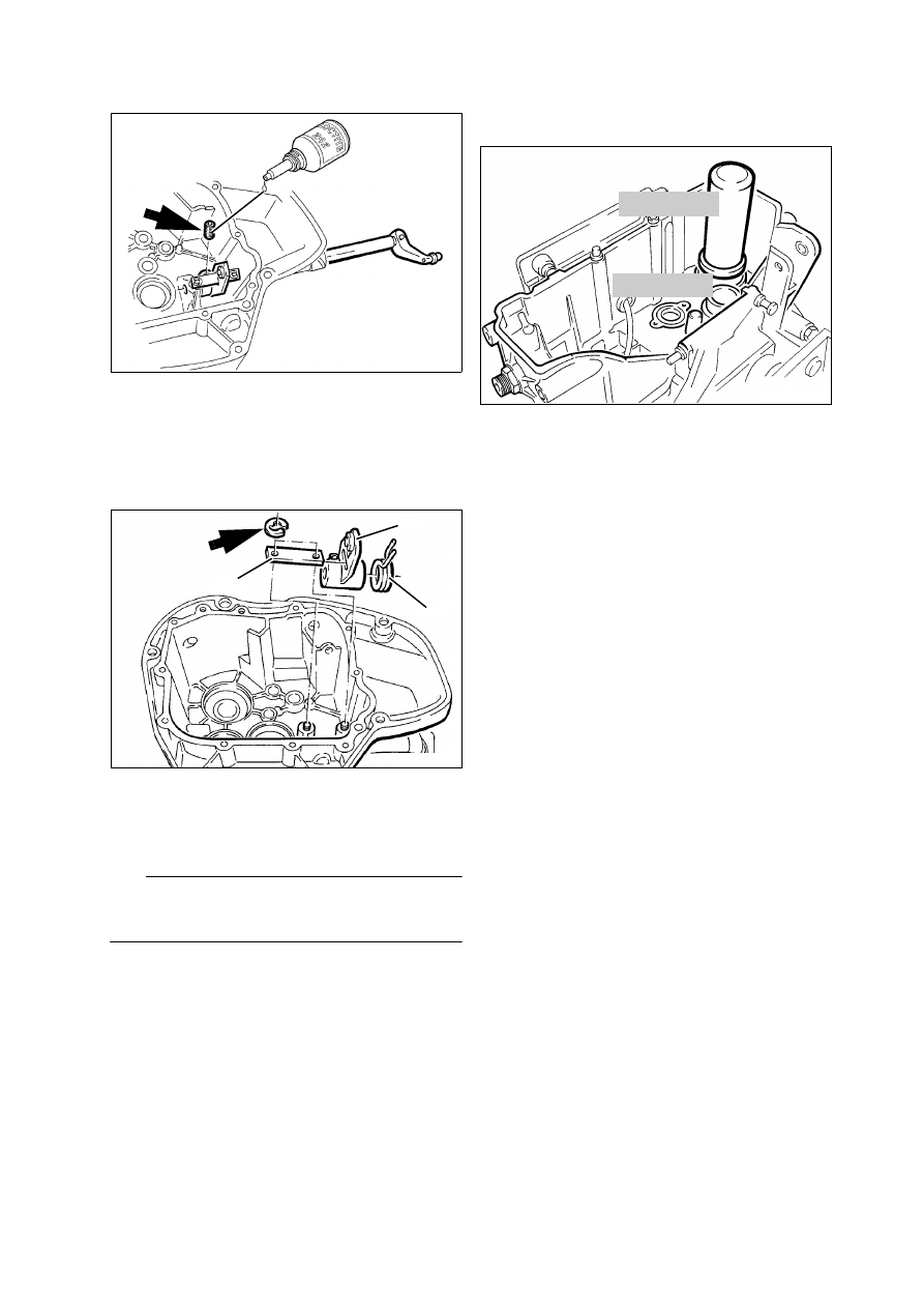
Removing selector shaft

Release setscrew (arrow) (secured with Loctite).

Pull out selector shaft together with gearshift le-
ver.

Removing segment

Remove retaining ring (arrow).

Remove segment (1) together with coil spring (2) 
and limit stop (3).

Install in the reverse order of removal.

e

 Caution:

Secure setscrew with Loctite 242; screw and hole 
must be clean and free of grease.

Tightening torque:

Setscrew, selector shaft

............................... 17 Nm

Drive in transmission case bent by 10 mm and fit 
cap.

Removing and installing shaft sealing 
ring on input shaft

Drive out shaft sealing ring from inside.

Fit shaft sealing ring using drift, 

BMW No. 23 1 760

 and handle, 

BMW No. 00 5 500

.

LT230110

LT230120

1

2

3

23 1 760

LT230130

00 5 500

23.14

Removing and installing shaft sealing 
ring for gear selector drum

Switch for gear indicator removed.

Gear selector drum removed.

Lever out shaft sealing ring with screwdriver.

Fit shaft sealing ring using drift, 
BMW No. 23 1 790 and handle, 
BMW No. 00 5 500.

Removing and installing bearing shell 
for taper roller bearing on input shaft

Heat transmission housing to 100 °C.

Remove bearing shell with the aid of support, 
BMW No. 00 8 560, and internal extractor, 
BMW No. 00 8 563

Fit new bearing shell in transmission housing 
while still hot.

Drive bearing shell to bottom of seat with drift, 
BMW No. 23 1 770, and handle 
BMW No. 00 5 500.

Removing and installing ball bearing 
on intermediate shaft

The intermediate shaft can only be replaced as a 
complete unit.

Remove ball bearing using universal puller, 
BMW No. 00 7 500.

To facilitate installation, heat ball bearing to 
80 °C. 

00 5 500

LT230140

23 1 790

00 8 560

LT230150

00 8 563

00 7 500

LT230160

23.15

Disassembling and assembling input 
shaft

Disassembling input shaft

Clamp spline end of input shaft in vice with jaw 
guard.

Remove retaining ring (1).

Using universal puller, BMW No. 00 7 500, and 
pressure tool (arrow), remove spur gear (3) to-
gether with taper roller bearing (2).

Also remove second taper roller bearing.

Assembling input shaft

Fit washer (6), coil spring (5), thrust piece (4) and 
spur gear (3) on input shaft.

Using universal puller, tension spur gear against 
coil spring until the 2nd groove (arrow) can be 
seen ahead of the spur gear.

Heat taper roller bearing to 100 °C and fit in po-
sition.

Fit retaining ring (1) in front of the taper roller 
bearing.

LT230170

5

6

4

3

2

1

00 7 500

LT230180

00 7 500

LT230190

23.16

Fit universal puller under the spur gear and pull 
down taper roller bearing as far as it will go on the 
retaining ring.

L

 Note:

There must be no clearance between the bearing 
and retaining ring in order to precisely determine the 
thickness of the spacer!

00 7 500

LT230200

23.17

Disassembling and assembling output 
shaft 

Before disassembling, measure axial clearance 
of spur gear for 1st, 2nd and 5th gears.

1st gear

 ....  0.10...0.30 mm (0.003937...0.01181in)

2nd gear

 ...  0.20...0.60 mm (0.007874...0.02362in)

5th gear

 ....  0.20...0.40 mm (0.007874...0.01575in)

Set axial clearance with spacer shim rings.

As part of the overall dimension, the spacer ring 
is fitted between the spur gear for 1st and 4th 
gear.

Removing ball bearing

Clamp output shaft in vice with jaw guards.

Remove ball bearing with universal puller, 
BMW No. 00 7 500.

LT230210

4.

5.

3.

1. Gang

2.

125.8

-0.1

00 7 500

LT230220

23.18

Removing spur gears

Remove spur gear for 1st (1) and 5th gear (2) with 
spacer shim rings.

Heat bearing bush (4) to 80 °C.

Carefully remove spur gear for 3rd gear (5) to-
gether with spacer shim ring (3) and bearing 
bush (4).

Heat bearing bush (6) to 80 °C.

Carefully remove spur gear for 4th gear (8), 
spacer shim ring (7) and bearing bush (6).

Remove retaining ring (9).

Remove serrated washer (10).

Remove spur gear for 2nd gear (11).

Remove split needle cage (12).

Remove serrated washer (13) and retaining 
ring (14).

LT230230

6

8

1

80°C

2

4

3

5

7

230240

4

3

5

LT230250

14

13

12

11

10

9

23.19

Installing spur gears

Slide serrated washer (10) over smooth end (ar-
row) onto output shaft up to the bearing seat.

Slide on retaining ring (11) and fit in groove 
ahead of serrated washer.

Fit split needle cage (9) well oiled.

Slide spur gear for 2nd gear (8) from the spline 
side over the needle cage with the window side 
first.

Fit serrated washer (7) followed by retaining 
ring (6).

Clamp output shaft in vice with jaw guards, 
spline facing upward.

Fit spur gear for 3rd gear (4) with windows facing 
upwards.

Fit spacer shim ring.

Heat wide bushing to 80 °C and slide on up to 
the spacer shim ring.

Fit spur gear for 5th gear (5) with claws facing 
downward.

Fit spacer shim ring.

Heat ball bearing up to 80 °C and slide on up to 
the spacer shim ring.

Turn output shaft in vice, splines facing down-
ward. 

Fit spur gear for 4th gear (1), claws facing down-
ward.

Fit spacer shim ring.

Check dimension

 125.8 mm (4.9528 in)

, include 

spacer shim ring between spur gears for 1st and 
4th gear.

Heat narrow bushing to 80 °C and slide on up to 
the spacer shim ring.

L

 Note:

Wide bushes are fitted on the spline side.

Fit spur gear for 1st gear with smooth side facing 
upward.

Fit spacer shim ring.

Heat ball bearing to 80 °C and fit.

As a check measure the axial clearance of the 
spur gears.

1st gear

 ....  0.10...0.30 mm (0.003937...0.01181in)

3rd gear

  ...  0.20...0.60 mm (0.007874...0.02362in)

5th gear

  ...  0.20...0.40 mm (0.007874...0.01575in)

LT230260

11

10

9

8

7

LT230270

4

5

LT230280

4.

3.

125.8

-0.1

1.

2.

5.

23.20

Installing transmission shafts

Heat bearing points for intermediate shaft and 
output shaft in the housing to 80°C.

Fit input shaft.

Install intermediate shaft  and output shaft to-
gether.

With the aid of light blows (plastic-headed ham-
mer), check that bearing is fitted in the base of 
the seat.

Installing gearshift forks

Fit gearshift fork for 5th gear (1) with short guide 
end facing upward in the bottom section of the 
output shaft.

Fit gearshift forks for 1st and 2nd gear (2) with 
short guide end facing downward in the upper 
section of the output shaft.

Fit gearshift fork for 3rd and 4th gear (3) with 
short guide end facing downward in the interme-
diate shaft.

L

 Note:

Lightly coat sleeves of guide pins with grease when 
fitting.

LT230290

80°C

LT230300

2

3

1


Content   ..  21  22  23  24   ..