BMW AG Motorcycle (K1100LT, K1100RS). Manual - part 6
 

  Index      Manuals     BMW AG Motorcycle (K1100LT, K1100RS). Repair Manual


Search            


Content   ..  4  5  6  7   ..


BMW AG Motorcycle (K1100LT, K1100RS). Manual - part 6


11.17

Dismantling and assembling freewheel

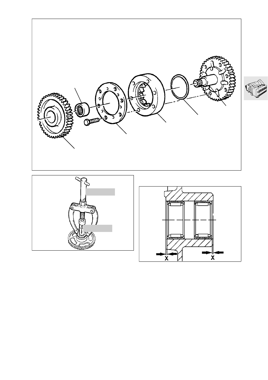
Stripping down freewheel

Pull freewheel gear (1) off layshaft (5).

Clamp the layshaft into a vice with soft jaws 
(smooth side down).

Remove cover plate (2).

Pull off freewheel cage (3).

Take out cup spring (4).

Pull needle roller bearing (6) out of the freewheel 
gear with counter-holder, BMW No. 00 8 570
and internal puller 21/3, BMW No. 00 8 574.

1

2

3

4

5

6

LT110160

LT110170

00 8 574

00 8 570

Assembling freewheel

Press the needle roller bearing into the freewheel 
gear so that distance (x) is the same at both 
sides.

Distance “X” .............. 0.4 

± 0.2

 mm (0.016 

± 0.008

 in)

LT110180

11.18

Place the cup spring in position.

Insert the freewheel (oiled with engine oil) into the 
outer race.

Install the outer race (with clamp block facing 
cover plate); the cup spring must snap into the 
outer race.

Place the cover plate in position.

Tightening torque:

Retaining screws.......................................... 10 Nm

Push the freewheel gear on to the layshaft while 
turning it clockwise.

Push the thrust washer and O-ring on to the lay-
shaft.

Removing and installing layshaft nee-
dle roller bearing 

Removing bearing

Heat the bearing seat to 100 °C.

Pull out the bearing with counter-support, 
BMW No. 00 8 570, and internal puller 21/3, 
BMW No. 00 8 574.

If the bearing is defective and cannot be pulled 
out, carefully cut through the needle roller sleeve 
with a grinder.

Installing bearing

Heat the bearing seat to 120 °C.

Centre the bearing and drive it in with a
21 mm (0.82 in) drift with a pin of smaller 
diameter (15.95 mm/0.628 in).

LT110190

11.19

Removing timing chain cover

Removing the Hall-effect signal transmitter

Remove cover (1).

Take off gasket (2).

Remove Hall-effect signal transmitter (3), noting 
the semi-circular shim washers.

L

 Note:

Mark the correct installed position of the adjusting 
washer on the engine block, or remove it in the TDC 
position.

Remove gate rotor (4) and take off adjusting 
washer (5).

Remove the crankshaft cover

Detach the coolant hose at the water pump and 
radiator.

Remove the cover.

Removing cylinder head cover

Remove the ignition leads.

Remove the cylinder head cover.

Removing and installing sealing ring in timing 
case cover

Drive the sealing ring out with a suitable drift.

Drive the sealing ring in from the inside using 
handle, BMW No. 00 0 500, and drift, 
BMW No. 11 1 610.

1

2

3

4

5

LT110200

LT110210

11.20

Removing the timing chain

Set cylinder 1 (timing end) to TDC, noting direc-
tion of rotation (arrow). Pin (1) on the crankshaft 
must be aligned with the marking on the housing.

Removing chain tensioner

Secure chain tensioner (1) with clamp, 
BMW No. 11 5 500, (arrow) and remove it.

3

2

1

4

LT110230

11 5 500

1

LT110240

Removing chain tensioner rail

Remove clip (2) and washer (3).

Pull out tensioner rail (4).

Renewing chain tensioner rail facing

LT110790

11.21

Removing camshaft chain sprockets

When taking out the retaining screws, hold the 
hexagon on the camshaft to prevent it from turn-
ing.

Remove chain guide (1).

4

2

3

LT110260

1

LT110250

Removing chain guide

Remove keepers (2) and washers (3) at the pivot 
pins.

Raise chain guide (4) slightly at the cylinder head 
and press it down again.

The toothed washer with eccentric (arrow) must 
project slightly.

Pull out the toothed washer. 

Take off the chain guide with the timing chain.

11.22

Removing, stripping down and assem-
bling cylinder head

Removing camshafts

Remove the bearing caps (1) for the thrust bear-
ings first, to prevent tilting.

Release tension uniformly at radial bearing
caps (2) and remove them.

Take out the camshafts.

Removing cylinder head

Unscrew the cylinder head bolts (3) with Torx in-
sert, BMW No. 00 2 610.

Strike the cylinder head lightly with a plastic-
faced hammer to dislodge it.

Removing bucket-type tappets

Using special suction tool, BMW No. 11 3 251
pull bucket tappets (5) out of the cylinder head.

Make a note of which tappet belongs to which 
valve.

4

3

1

2

5

LT110270

11.23

Removing valves

Screw support plate, BMW No. 11 1 749, for the 
valve spring clamping tool on to the rear of the 
cylinder head.

Attach valve spring clamping tool, 
BMW No. 11 1 740.

Use pressure cage (1), BMW No. 11 1 748.

Place the cylinder head flat on a wooden board 
and clamp the valve spring.

Pull valve collets (1) out with a magnetic screw-
driver.

Release valve spring (3) and remove the various 
components.

Upper spring plate (2), lower spring plate (4).

Pull out the valve stem seal with pliers, 
BMW No. 11 1 250.

Remachining valve seat

D = valve diameter
B = valve seat width

When remachining, the correct width of the valve 
seat must always be maintained.

L

 Note:

Machine the valve seat with turning tool, 
BMW No. 11 0 500.

If the valve seat has been remachined, a new 
valve must be installed.

LT110280

11 1 749

1

LT110290

11 1 740

2

1

3

4

LT110300

LT110310

11.24

Installing valve and valve stem seal

L

 Note:

If a valve was removed, the valve stem seal must be 
renewed.

Oil the stem when installing the valve.

Insert the lower spring plate.

Push assembly sleeve (arrow), 
BMW No. 11 1 960, on to the valve stem.

Drive in sealing ring (1) with drift, 
BMW No. 11 5 601, until the drift reaches the 
cylinder head.

e

 Caution:

Remember to remove the assembly sleeve from the 
valve stem.

Insert the valve spring.

Install the upper spring plate.

Clamp the valve spring, lightly oil the valve collets 
and insert them, then release the spring.

Clean and oil the bucket-type tappet before in-
serting.

1

LT110320


Content   ..  4  5  6  7   ..