BMW AG Motorcycle (F 650 GS). Manual - part 30
 

  Index      Manuals     BMW AG Motorcycle (F 650 GS). Repair Manual


Search            


Content   ..  28  29  30  31   ..


BMW AG Motorcycle (F 650 GS). Manual - part 30


34.8

34 21 222 

Removing and installing 

rear brake calliper

e

 Caution:

Refer to notes on the hazards involved in handling 
brake fluid.

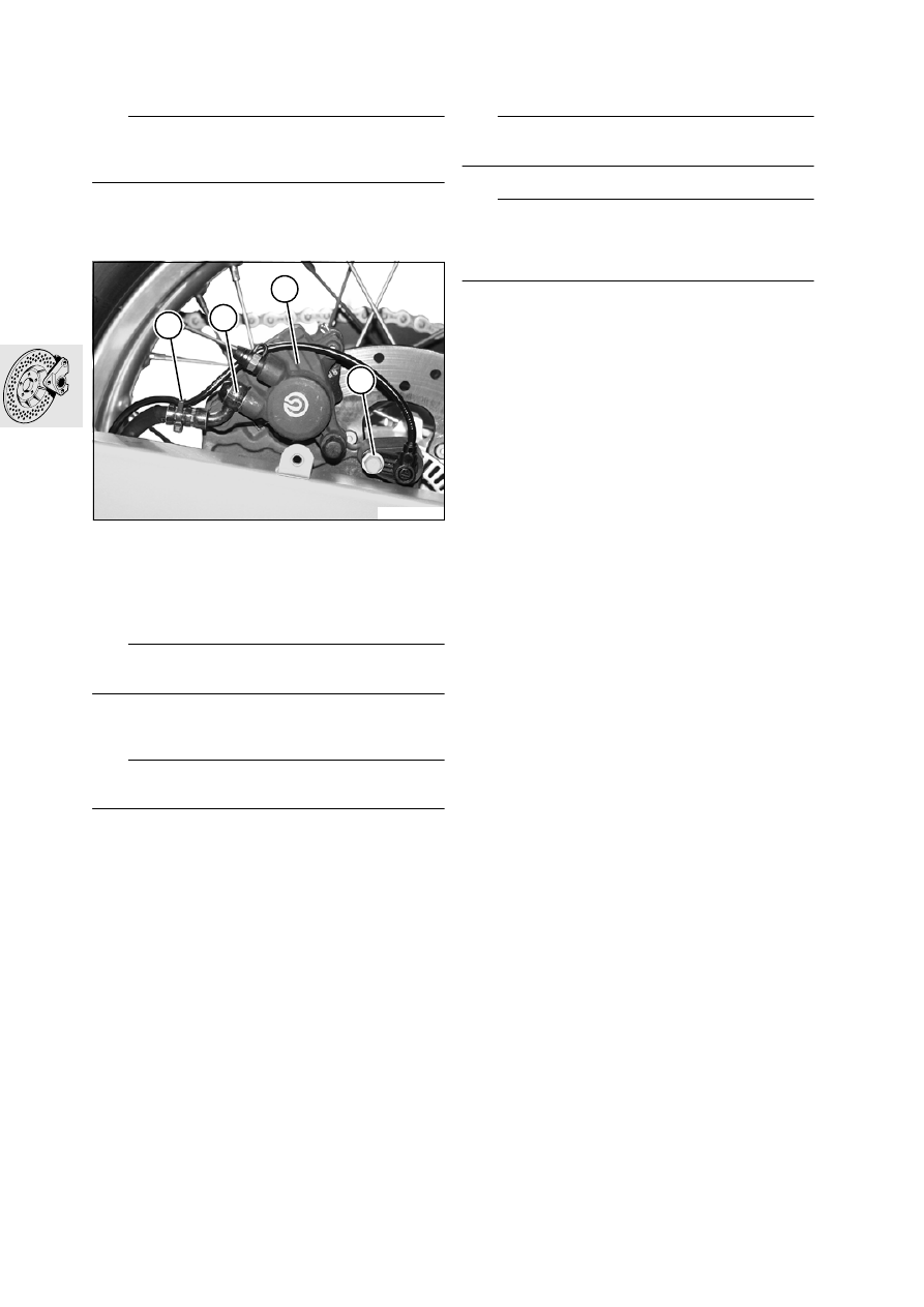
Remove wheel cover together with chain cover.

Press the brake calliper against the brake disc in 
order to force the pistons back

Cut through cable tie (1).

[ABS] Remove fastener securing ABS sensor (4) 
and remove ABS sensor.

Disconnect brake line (2) at brake calliper and 
seal the line.

e

 Caution:

Do not operate the brake with the wheel removed.

Remove rear wheel.

a

....................................................See Group 36

e

 Caution:

Do not damage brake pads.

Remove brake calliper (3) from the rear swinging 
fork.

Installation is the reverse of the removal proce-
dure.

L

 Note:

Remove sealing rings for brake line.

e

 Caution:

Top up brake fluid and bleed brake system.
Operate brake several times until brake pads are 
correctly seated.

Tightening torque:

Brake line to brake calliper ........................... 18 Nm
ABS sensor to bracket ................................... 9 Nm
Quick-release axle ..................................... 100 Nm
Wheel cover bracket to swinging arm............. 9 Nm

34 21 200 

Removing and installing rear 

brake pads

See Group 00

E340080

1

2

3

4

34.9

Removing and installing rear brake 
piston

Remove rear brake calliper.

Remove the split-pin keeper (1) from retaining 
pin (2).

Drive the retaining pin out towards the wheel 
side.

Remove brake pads (6).

Hold a cloth over the brake calliper.

e

 Caution:

Do not insert your fingers between the pistons; risk 
of injury.

Carefully press out brake piston (3), using a 
compressed air gun at the brake line connection.

Remove the two sealing rings (4, 5) from the 
brake piston bore.

Examine the brake calliper piston for damage.

Installation is the reverse of the removal proce-
dure: pay particular attention to the following.

Coat new sealing rings (4, 5) with brake fluid and 
install.

Coat the brake piston (3) with the assembly fluid 
supplied and install.

e

 Caution:

Keep the brake piston parallel with its bore when in-
stalling.

Using piston compressor, BMW No. 34 1 500, if 
necessary press the piston fully back.

Install the brake pads.

E340090

1

5

4

3

2

6

34.10

34 21 301 

Removing and installing 

rear brake disc

e

 Caution:

Do not operate the brake with the wheel removed.

Remove rear wheel.

a

....................................................See Group 36

L

 Note:

Retaining screws (1) are secured with Loctite 243 
and should be heated if necessary before removal.

Remove retaining screws (1) with brake disc.

Remove brake disc.

Installation is the reverse of the removal proce-
dure: pay particular attention to the following.

e

 Caution:

The inscription on the brake disc must face towards 
the outside.

Clean the threads of the securing screws and 
wheel hub, coat threads with Loctite 243 and in-
stall the screws.

Tightening torque:

Brake disc to rear-wheel hub
(clean thread + Loctite 243)............................ 9 Nm

Checking brake disc for wear

See Group 00

Checking rear brake disc for lateral 
runout

Place motorcycle on its centre stand.

Remove wheel cover together with chain cover.

Attach dial gauge holder, BMW No. 00 2 500, to 
the rear swinging arm.

Using dial gauge, BMW No. 00 2 510, measure 
lateral runout.

Lateral runout.................... max. 0.25 mm (0.010 in)

Replacing primary sealing boot front 
brake master cylinder

See Group 00

E340100

1

E340110

00 2 500

00 2 510

34.11

Removing and installing front brake 
master cylinder

Place the motorcycle on its main (centre) stand.

e

 Caution:

Refer to notes on the hazards involved in handling 
brake fluid.

Drain the brake system.

Remove brake microswitch.

Disconnect brake hose (1) from the brake master 
cylinder.

Remove screws securing brake master 
cylinder (2).

Installation is the reverse of the removal proce-
dure: pay particular attention to the following.

L

 Note:

Replace the sealing rings for the brake hose.

e

 Caution:

Top up brake fluid and bleed brake system.
Operate brake several times until brake pads are 
correctly seated.

Tightening torque:

Brake hose to brake master cylinder ............ 18 Nm
Brake master cylinder to handlebar ................ 9 Nm

32 72 119 

Removing and installing 

handbrake lever

See Group 32

Replacing primary sealing boot, 
rear brake master cylinder

See Group 00

34 31 001 

Removing and installing 

rear brake master cylinder

Place the motorcycle on its main (centre) stand.

e

 Caution:

Refer to notes on the hazards involved in handling 
brake fluid.
Do not operate the brake when dismantled.

Drain the brake system.

Disengage piston thrust rod (3).

Disconnect brake line (5).

Disconnect hose from reservoir (4).

Remove fasteners (6) securing brake master cyl-
inder.

Installation is the reverse of the removal proce-
dure: pay particular attention to the following.

Secure brake line to brake master cylinder.

E340200

1

2

E340250

3

6

5

4

34.12

e


Caution:

Top up brake fluid and bleed brake system.
Operate brake several times until brake pads rest on 
disc.

Play at piston thrust 
rod .............................. 0.5...1.5 mm (0.02...0.06 in)

Tightening torque:

Brake line at master cylinder ........................ 18 Nm
Brake master cylinder to frame....................... 9 Nm

35 21 000 

Removing and installing 

footbrake lever

Remove footrest plate (1).

Disengage piston thrust rod (4).

Remove hexagon fit bolt (2).

Remove brake pedal (3), leaving torsion 
spring (5) on the frame.

Installation is the reverse of the removal proce-
dure: pay particular attention to the following.

L

 Note:

Grease the bearing bushing with 
Staburags NBU 30 PTM.
Check play at piston thrust rod and adjust if neces-
sary.
See removal and installation of brake master cylin-
der.

e


Caution:

Check operation of brake-light switch (6).

Play at piston thrust 
rod .............................. 0.5...1.5 mm (0.02...0.06 in)

Tightening torque:

Brake pedal to frame.................................... 21 Nm

Checking play at piston thrust rod, 
adjusting if necessary

Checking play at piston thrust rod

With no load applied to the brake pedal, i.e. lug 
of lever against stop on frame (arrow), play must 
be perceptible at piston thrust rod (7).

L

 Note:

Adjust the piston thrust rod if no play is perceptible.

Adjusting play at piston thrust rod

a

........................................................ See below.

E340040

2

1

6

4

3

5

E340270

7

34.13

Adjusting play at piston thrust rod

Insert feeler gauge (1) 0.2 mm (0.008 in) thick be-
tween the lug of the brake pedal and the stop on 
the frame (arrow).

Slacken nut (2) on the thrust rod at the brake 
master cylinder.

Turn piston rod (3) clockwise to obtain play.

Carefully back off piston rod to take up play and 
tighten locknut.

Tighten the locknut on the piston rod and remove 
the feeler gauge.

Tightening torques:

Locknut .......................................................... 9 Nm

34 52 044 

Removing and installing 

front ABS sensor

Place the motorcycle on its main (centre) stand.

Remove seat.

Remove left cover.

Remove the fastener securing ABS sensor (4) to 
the front fork.

Disconnect ABS plug (5).

Press ABS plug (6) to the rear and out of its hold-
er.

Cut the cable ties on the brake hose and the in-
strument carrier.

Remove the sensor cable from the holder on the 
front fork.

Remove the sensor and the cable.

Installation is the reverse of the removal proce-
dure.

Check the ABS sensor gap and adjust if neces-
sary.

a

....................................................See Group 34

Tightening torques:

Front ABS sensor ........................................... 9 Nm

E340260

1

3

2

E340150

4

E340160

5

6

34.14

34 51 610 

Removing front ABS sensor 

ring

e

 Caution:

Do not operate the brake with the wheel removed.

Remove front wheel.

a

....................................................See Group 36

L

 Note:

Retaining screws (1) are secured with Loctite 243 
and should be heated if necessary before removal.

Remove retaining screws (1) from brake disc.

Remove sensor ring (2).

Installation is the reverse of the removal proce-
dure: pay particular attention to the following.

Clean the threads of the securing screws and 
wheel hub, coat threads with Loctite 243 and in-
stall the screws.

Check the ABS sensor gap and adjust if neces-
sary.

a

....................................................See Group 34

Tightening torque:

Brake disc to front-wheel hub
(clean thread + Loctite 243)............................ 9 Nm

34 52 111 

Removing and installing 

rear ABS sensor

Place motorcycle on its centre stand.

Remove seat.

Remove wheel cover together with chain cover.

Cut through cable tie (3).

Remove fastener securing ABS sensor (4) and 
remove ABS sensor.

Disconnect ABS sensor plug (5) and unclip the 
plug from the control-unit holder.

Raise the rear frame.

a

.................................................... See Group 46

Remove the ABS sensor cable from the clip on 
the holder of the ABS control unit.

Cut the cable tie at the interface between brake 
line and brake hose.

Open 2 clips on the swinging arm and remove 
the ABS sensor cable.

E340070

1

2

E340080

3

4

E340280

5

34.15

Cut the cable ties on the brake hose.

Installation is the reverse of the removal proce-
dure.

Check the speed/ABS sensor gap and adjust if 
necessary.

a

....................................................See Group 34

Tightening torque:

ABS sensor to holder ..................................... 9 Nm
Wheel cover bracket to swinging arm............. 9 Nm

34 51 619 

Removing and installing 

rear ABS sensor ring

e

 Caution:

Do not operate the brake with the wheel removed.

Remove rear wheel.

a

....................................................See Group 36

L

 Note:

Retaining screws (1) are secured with Loctite 243 
and should be heated if necessary before removal.

Remove securing screws (1) from sensor ring.

Remove sensor ring (2).

Installation is the reverse of the removal proce-
dure: pay particular attention to the following.

Clean the threads of the securing screws and 
wheel hub, coat threads with Loctite 243 and in-
stall the screws.

Check the speed/ABS sensor gap and adjust if 
necessary.

a

....................................................See Group 34

Tightening torque:

Sensor ring to rear-wheel hub
(clean thread + Loctite 243)............................ 5 Nm

34 51 050 

Removing and installing ABS 

control unit

e

 Caution:

All work on the ABS control unit must be carried out 
by an authorised BMW workshop.

Remove the rear frame.

a

....................................................See Group 46

Remove front brake lines.

a

......................................................... See below

e

 Caution:

If brake fluid escapes, it may damage paint.
Line connections must be protected against dirt 
penetration; seal or cover ends of lines and ports.

Disconnect rear brake line from control unit.

Remove screws securing the control unit to the 
holder.

Disconnect plug for control unit (3).

Carefully push the rear brake lines to one side.

Lift the control unit, pull it to the rear and remove.

Installation is the reverse of the removal proce-
dure: pay particular attention to the following.

E340100

1

2

E340210

3


Content   ..  28  29  30  31   ..