BMW AG Motorcycle (F 650 GS). Manual - part 27
32.12
32 72 305
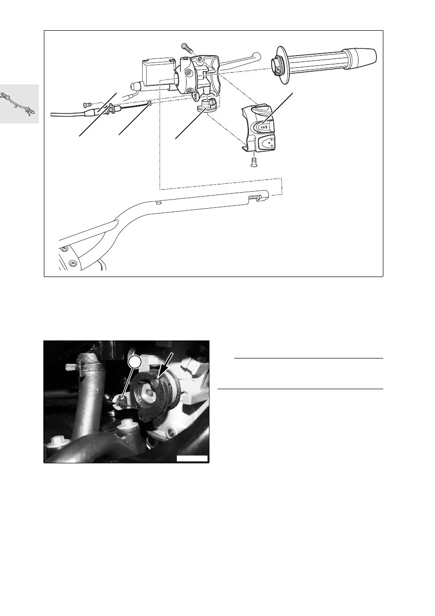
Removing and installing
throttle cable
–
Remove seat.
–
Remove left cover.
•
Disengage throttle cable from adapter (arrow).
•
Remove circlip (5) from throttle-cable holder and
disengage throttle cable.
•
Pull the cable out toward the handlebar.
•
Remove cover (4).
•
Remove fastener for throttle cable (1) from in-
strument cluster housing.
•
Disengage throttle-cable adapter (3) and disen-
gage nipple (4).
•
Remove the throttle cable.
•
Installation is the reverse of the removal proce-
dure: pay particular attention to the following.
L
Note:
Make sure that the cable is not kinked when in-
stalled.
•
Adjust throttle-cable play with adjusting
screw (5).
Throttle cable play................approx. 1 mm (0.04 in)
X
Tightening torques:
Cover of multi-function switch ........................ 1 Nm
E320170
1
4
3
2
5
E320180
5