BMW AG Motorcycle (F 650 GS). Manual - part 24
 

  Index      Manuals     BMW AG Motorcycle (F 650 GS). Repair Manual


Search            


Content   ..  22  23  24  25   ..


BMW AG Motorcycle (F 650 GS). Manual - part 24


23.10

23 00 622 

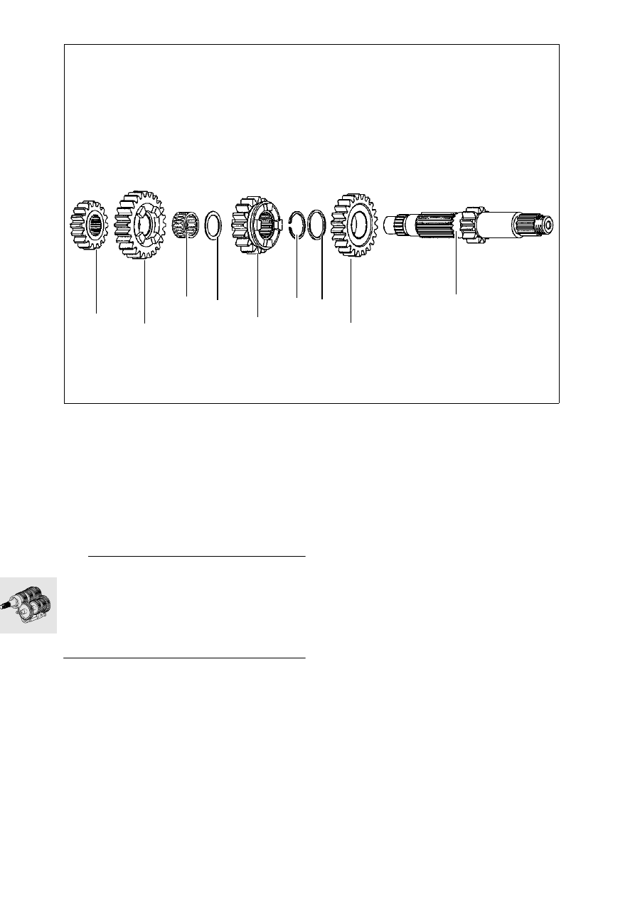
Disassembling and 

reassembling compensating shaft

Clamp the compensating shaft in a vise fitted 
with protective jaws.

Pull off gearwheels (1, 2).

Pull off needle roller bearing (3) and washer (4).

Pull off gearwheel (5).

Remove circlip (6) with special pliers, 
BMW No. 23 4 500.

Pull off washer (7) and gearwheel (8).

L

 Note:

Inspect all bearings, bearing journals, tooth flanks, 
keyways and ring grooves for signs of wear.
Renew gears only together with the corresponding 
meshing gears.
Edges of ring grooves must not be blunt.
Always renew circlips and install them only with spe-
cial pliers, BMW No. 23 4 500.

Assembly is the reverse of the disassembly pro-
cedure.

F230060

1

2

3

4

5

6

7

8

9

23.11

Checking countershaft for wear

Wear limits:
“A” Shaft diameter, 
magneto side ...................min. 16.98 mm (0.669 in)
“B” Shaft diameter, clutch 
side ..................................min. 24.97 mm (0.983 in)
Inside diameter of bearing seat
4th gear sliding 
gearwheel ....................... max. 25.53 mm (1.005 in)
Runout .................................... 0.02 mm (0.0008 in)

11 11 205 

Replacing gearbox mainshaft 

bearings

L

 Note:

To protect the gasket surfaces of the engine block, 
place the old gasket under the bearing puller.
Always renew the mainshaft sealing ring.

Heat the left of the engine block to 80 — 100 °C 
(176 — 212 °F).

Using bearing puller plate, BMW No. 11 6 561
spindle, BMW No. 11 6 562, and spreader 
sleeve, BMW No. 11 6 564, pull off the ball bear-
ing.

Drive out the mainshaft sealing ring from the in-
side.

Heat the right of the engine block to 80 - 100 °C 
(176 - 212 °F).

Working from outside and using a suitable sock-
et, press the bearing through to the other side.

Installation is the reverse of the removal proce-
dure: pay particular attention to the following.

To install the bearings, heat the engine block to 
80 - 100 °C (176 - 212 °F).

F230070

B

A

E230040

11 6 564

11 6 561

11 6 562

23.12

11 11 210 

Replacing gearbox 

compensating shaft bearings

L

 Note:

To protect the gasket surfaces of the engine block, 
place the old gasket under the bearing puller.

Heat the left of the engine block to 80 — 100 °C 
(176 — 212 °F).

Using bearing puller plate, BMW No. 11 6 561
spindle, BMW No. 11 6 562, and spreader 
sleeve, BMW No. 11 6 565, pull off the ball bear-
ing.

Heat the right of the engine block to 80 - 100 °C 
(176 - 212 °F).

Using bearing puller plate, BMW No. 11 6 561
spindle, BMW No. 11 6 562, and spreader 
sleeve, BMW No. 11 6 564, pull off the ball bear-
ing.

Installation is the reverse of the removal proce-
dure: pay particular attention to the following.

To install the bearings, heat the engine block to 
80 - 100 °C (176 - 212 °F).

Wear limit values for bearing seats in housing:
Magneto side:
Countershaft ............... max. Ø 46.99 mm (1.850 in)
Mainshaft .................... max. Ø 62.02 mm (2.442 in)
Clutch side:
Countershaft ............... max. Ø 51.99 mm (2.047 in)
Mainshaft .................... max. Ø 46.99 mm (1.850 in)

23 00 600 

Installing gearbox shafts

L

 Note:

The gearbox shafts are easier to install if the crank-
shaft is removed beforehand.

Install the countershaft and mainshaft together, 
coating the main bearing points with 
Optimoly MP 3.

Drive the shafts in against their seats with light 
blows of a plastic-faced hammer. 

F230090

23.13

23 00 640 

Installing selector shaft

Install index lever (2) with index spring (1) in 
housing.

Engage pawl spring (4) on shift pawl (3).

Insert selector shaft (6) in housing and secure in-
dex lever (5) in position.

Push hairpin spring (7) with sleeve (8) on to se-
lector shaft (7).

Engage the hairpin spring to the bearing journal.

23 00 658 

Installing selector forks

Insert selector fork (9) in shift gear of counter-
shaft.

Insert selector rod and swivel together with the 
selector fork in the direction of the crankshaft.

Insert selector forks (10, 11) in the correspond-
ing shift gears of the mainshaft.

Insert selector rod and swivel it outwards togeth-
er with the selector forks.

Drive the selector shafts onto their seats with 
light blows of a plastic-faced hammer.

23 00 651 

Installing selector drum

Install the selector drum in the neutral position. 
The contact pin in the plastic plate is above the 
neutral indicator switch in the housing.

Press back index lever and selector pawl and in-
stall selector drum.

Move index lever and selector pawl into mesh.

Turn selector forks so that they engage the se-
lector drum.

L

 Note:

Select all gears in succession, at the same time 
checking that the selector pawl is withdrawn freely 
from the selector drum in all gears.

Check gearbox functions.

Assemble the engine.

a

....................................................See Group 11

L

 Note:

The clicking sound as the selector pawl engages 
must be clearly audible.

F230100

2

1

F230110

3

5

6

7

8

4

F230120

9

11

10

23.14

Select all gears once again and move the shift le-
ver slowly to the “0” position.

Cover the splines on the selector shaft with slide-
on sleeve, BMW No. 21 4 620.

Using drift, BMW No. 21 4 630, drive in sealing 
ring.

Drive in the mainshaft sealing ring with drift, 
BMW No. 23 4 550, and sliding sleeve, 
BMW No. 23 4 540.

Install the engine.

a

....................................................See Group 11

27.1

Contents

Page

27

Technical Data

............................................................................................................................... 3

Removing and installing chain, chainwheel and chain sprocket

 .......................5

Removing and installing chain

 ..................................................................................................5

Removing and installing chain guide rail ..............................................................................................5
Removing and installing chain takeup roller .........................................................................................5

Removing chainwheel

 ...................................................................................................................6

Removing chain sprocket

 ............................................................................................................6

Removing and installing chain guide rail with swinging arm installed

 .....................7

Adjusting chain tension

 ................................................................................................................7

See Group 00 ......................................................................................................................................7

27 Drive chain

27.2

27.3

27

Technical Data

F 650 GS

Chain drive

Number of teeth on chain sprocket

16

Number of teeth on chainwheel

47

Secondary ratio

1:2.937

Secondary drive

O-ring chain 
5/8" x 1/4"

Chain links

112

Chain length

mm (in) 1000 (39.4)

Roller diameter

mm (in) 10.16 (0.400)


Content   ..  22  23  24  25   ..