Motorcycle BMW R1150RT. Manual - part 84
 

  Index      motorcycles     Motorcycle BMW R1150RT - service repair manual 2001 year


Search            


Content   ..  82  83  84  85   ..


Motorcycle BMW R1150RT. Manual - part 84


61.5

61 13 

Removing and installing central 

electrical equipment box

e

 Attention:

Switch off ignition.
Disconnect earth (ground) lead from battery.
Insulate earth (ground) lead.

Remove the seat.

Remove small side fairing panels.

Remove screws (2) securing bottom of central 
electrical equipment box.

Remove screws (1) securing top of central elec-
trical equipment box.

Pull cable tray down and remove.

Remove relay and relay base or if necessary, dis-
connect entire wiring harness and remove com-
plete with fuse box.

Installation is the reverse of the removal proce-
dure.

Switch on the ignition.

Without starting the engine, fully open the throttle 
once or twice so that the Motronic control unit 
can register the throttle-valve positions.

L

 Note:

Disconnecting the battery deletes all entries (e.g. 
faults, settings) stored in the Motronic control unit’s 
memory.
Loss of settings can temporarily impair the operat-
ing characteristics when the engine is restarted.

61 13 

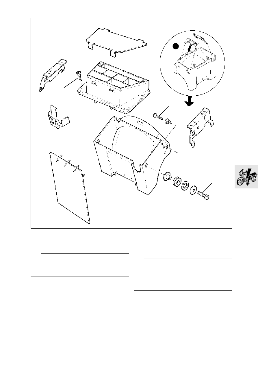
Disassembling and assembling 

central electrical equipment box

See illustration (3).

3

1

R22610050

2

2

61.6

61 31 

Relay positions/fuse assign-

ments (central electrical equipment 
box)

Relay positions

1. Flasher unit 
2. Indicator damping
3. Coded plug for Motronic (not used)
4. Starter motor relay
5. Relief relay
6. Horn relay
7. Fuel pump relay 
8. Motronic relay 
9. ABS warning relay 
10.Lighting relay

Fuse assignments 
(No. 1 on left, looking forwards)

1. Instrument cluster (telltale lights, revolution 

counter), indicator damping, windscreen 
adjuster ........................................................ 4 A

2. Parking light, tail light ................................... 4 A
3. Windscreen adjuster, power sockets 1 and 2, 

FID, OE socket, radio ................................. 15 A

4. Horn.......................................................... 7.5 A
5. Motronic control unit, Motronic relay, 

diagnosis connector................................... 10 A

6. Fuel-pump relay (injection valves,

cycle valves, oxygen sensor) ...................... 10 A

7. Heated handlebar grips................................ 4 A
8. Radio ........................................................... 4 A
9. Not used
10.Fog lamp relay............................................ 15 A

R22610040

9

8

7

6

5

1

2

3

4

10

R22610040

10

1

61.7

61 11 

Wiring-harness routing, frame

e

 Attention:

Use (yellow) galvanized screws for the ground 
(earth) connection to the engine.
Screws with unsuitable corrosion proofing can 
cause the electrical resistance to rise as high as 
80

. Run wiring harness without kinking and avoid 

risk of abrasion.
Note the number and position of the cable straps.

Apply a thin coating of contact grease, 
e.g. CENTOPLEX 3 CU to the central earth 
(ground) point, which must be cleaned to bright 
metal first.

L

 Note:

When removing the wiring harness, take out the 
central electrical equipment box at the same time.
When installing, install the central electrical equip-
ment box first.

Tightening torque:

Ground terminal to engine block .................... 9 Nm

61.8

61 11 

Wiring-harness routing/connec-

tion in central electrical equipment box

R28610070


Content   ..  82  83  84  85   ..