Kawasaki Ninja 650R, ER-6f, ER-6f ABS Motorcycle. Service Manual (2009-2011 year) - page 2
 

  Index      Manuals     Kawasaki Ninja 650R, ER-6f, ER-6f ABS Motorcycle. Service Manual (2009-2011 year)


Search            copyright infringement  


Content      ..      1      2      3      ..


Kawasaki Ninja 650R, ER-6f, ER-6f ABS Motorcycle. Service Manual (2009-2011 year) - page 2


PERIODIC MAINTENANCE 2-31

Periodic Maintenance Procedures

Brake System

Brake Fluid Leak (Brake Hose and Pipe) Inspection

For models equipped with an ABS, remove the battery
case (see Battery Case Removal in the Frame chapter).

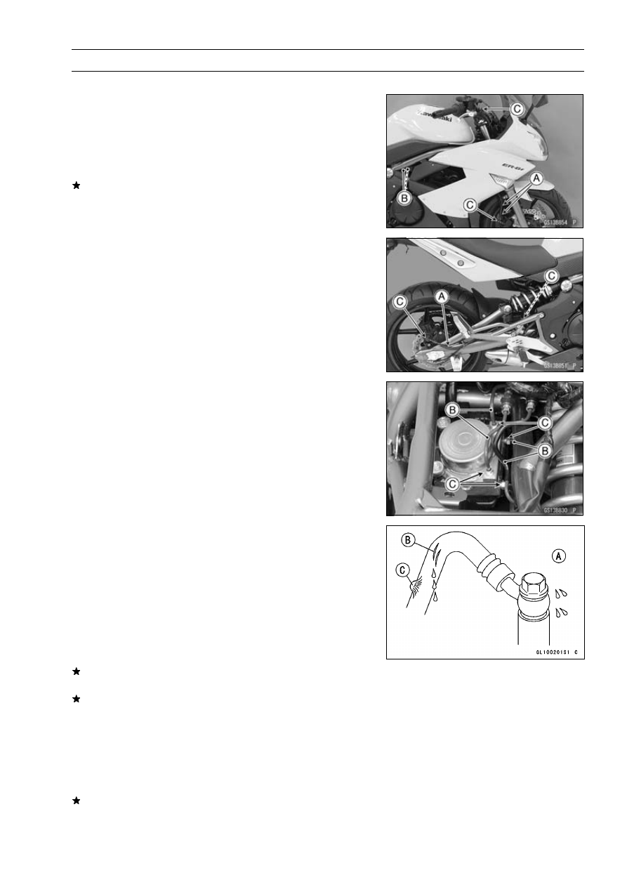
Apply the brake lever or pedal, and inspect the brake fluid
leak from the brake hoses [A], pipes (ABS equipped mod-
els) [B] and fittings [C].
If the brake fluid leaked from any position, inspect or re-
place the problem part.

Brake Hose and Pipe Damage and Installation
Condition Inspection

For models equipped with an ABS, remove the battery
case (see Battery Case Removal in the Frame chapter).

Inspect the brake hoses, fittings and pipes (ABS equipped
models) for deterioration, cracks and signs of leakage.

The high pressure inside the brake line can cause fluid
to leak [A] or the hose, pipes (ABS equipped models) to
burst if the line is not properly maintained. Bend and twist
the rubber hose while examining it.
Replace the hose and pipe (ABS equipped models) if any
crack [B], bulge [C] or leakage is noticed.
Tighten any brake hose banjo bolts and brake pipe joint
nuts.

Torque - Brake Hose Banjo Bolts: 25 N·m (2.5 kgf·m, 18

ft·lb)

Brake Pipe Joint Nuts: 18 N·m (1.8 kgf·m, 13 ft·lb)

(EX650D Models)

Inspect the brake hose routing.
If any brake hose and pipe (ABS equipped models) rout-
ing is incorrect, run the brake hose according to Cable,
Wire, and Hose Routing section in the Appendix chapter.

2-32 PERIODIC MAINTENANCE

Periodic Maintenance Procedures

Brake Fluid Level Inspection

Check that the brake fluid level in the front brake reservoir
[A] is above the lower level line [B].

NOTE

Hold the reservoir horizontal by turning the handlebar
when checking brake fluid level.

If the fluid level is lower than the lower level line, fill the
reservoir to the upper level line [C] in the reservoir.

Remove the seat (see Seat Removal in the Frame chap-
ter).

Check that the brake fluid level in the rear brake reservoir
[A] is above the lower level line [B].
If the fluid level is lower than the lower level line, fill the
reservoir to the upper level line [C].

WARNING

Change the brake fluid in the brake line completely
if the brake fluid must be refilled but the type and
brand of the brake fluid that is already in the reser-
voir are unidentified. After changing the fluid, use
only the same type and brand of fluid thereafter.

Recommended Disc Brake Fluid

Grade:

DOT4

Follow the procedure below to install the rear brake fluid
reservoir cap correctly.

First, tighten the rear brake fluid reservoir cap [B] clock-
wise [C] by hand until slight resistance is felt indicating
that the cap is seated on the reservoir body, then tighten
the cap an additional 1/6 turn [D] while holding the brake
fluid reservoir body [A].

PERIODIC MAINTENANCE 2-33

Periodic Maintenance Procedures

Brake Pad Wear Inspection

Check the lining thickness [A] of the pads in each caliper.
If the lining thickness of either pad is less than the service
limit [B], replace both pads in the caliper as a set.

Pad Lining Thickness

Standard:

Front [C]

4.5 mm (0.18 in.)

Rear [D]

5.0 mm (0.20 in.)

Service Limit: 1 mm (0.04 in.)

Brake Operation Inspection

Inspect the operation of the front and rear brake by run-
ning the vehicle on the dry road.
If the brake operation is insufficiency, inspect the brake
system.

WARNING

When inspecting by running the vehicle, note a
surrounding traffic situation enough in the place of
safety.

Brake Light Switch Operation Inspection

Turn the ignition switch ON.

The brake light [A] should go on when the brake lever is
applied or after the brake pedal is depressed about 10
mm (0.39 in.)
.

If it does not, adjust the brake light switch.

Remove the right footpeg stay (see Footpeg Stay Re-
moval in the Frame chapter).

While holding the switch body, turn the adjusting nut to
adjust the switch.

Switch Body [A]
Adjusting Nut [B]
Light sooner as the body rises [C]
Light later as the body lowers [D]

CAUTION

To avoid damaging the electrical connections in-
side the switch, be sure that the switch body does
not turn during adjustment.

2-34 PERIODIC MAINTENANCE

Periodic Maintenance Procedures

If it does not go on, inspect or replace the following items.

Battery (see Charging Condition Inspection in the Elec-
trical System chapter)
Brake Light (LED) (see Tail/Brake Light (LED) Removal
in the Electrical System chapter)
Main Fuse 30 A and Taillight Fuse 10 A (see Fuse In-
spection in the Electrical System chapter)
Front Brake Light Switch [A] (see Switch Inspection in
the Electrical System chapter)
Rear Brake Light Switch (see Switch Inspection in the
Electrical System chapter)
Harness (see Wiring Inspection in the Electrical System
chapter)

Suspensions

Front Forks/Rear Shock Absorber Operation
Inspection

Pump the forks down and up [A] 4 or 5 times, and inspect
the smooth stroke.
If the forks do not smoothly or noise is found, inspect the
fork oil level or fork clamps (see Front Fork Oil Change in
the Suspension chapter).

Pump the seat down and up [A] 4 or 5 times, and inspect
the smooth stroke.
If the shock absorber does not smoothly stroke or noise
is found, inspect the oil leak (see Rear Shock Absorber
Oil Leak Inspection).

Front Fork Oil Leak Inspection

Visually inspect the front forks [A] for oil leakage.
Replace or repair any defective parts, if necessary.

PERIODIC MAINTENANCE 2-35

Periodic Maintenance Procedures

Rear Shock Absorber Oil Leak Inspection

Visually inspect the shock absorber [A] for oil leakage.
If the oil leakage is found on it, replace the shock absorber
with a new one.

Steering System

Steering Play Inspection

Raise the front wheel off the ground using the jack (see
Front Wheel Removal in the Wheels/Tires chapter).

With the front wheel pointing straight ahead, alternately
tap each end of the handlebar. The front wheel should
swing fully left and right from the force of gravity until the
fork hits the stop.
If the wheel binds or catches before the stop, the steering
is too tight.

Feel for steering looseness by pushing and pulling [A] the
forks.
If you feel looseness, the steering is too loose.

NOTE

The cables and wiring will have some effect on the mo-
tion of the fork which must be taken into account.

Be sure the leads and cables are properly routed.

The bearings must be in good condition and properly
lubricated in order for any test to be valid.

Steering Play Adjustment

Remove the steering stem head (see Stem, Stem Bearing
Removal in the Steering chapter).

Bend the claws [A] of the claw washer straighten.

Remove the steering stem locknut [B] and claw washer.

Adjust the steering.

Special Tool - Steering Stem Nut Wrench [A]: 57001-1100

If the steering is too tight, loosen the stem nut [B] a fraction
of a turn.
If the steering is too loose, tighten the stem nut a fraction
of a turn.

NOTE

Turn the stem nut 1/8 turn at time maximum.

2-36 PERIODIC MAINTENANCE

Periodic Maintenance Procedures

Install the claw washer [A] so that its bent side [B] faces
upward, and engage the bent claws with the grooves of
stem locknut [C].

Hand tighten the stem locknut until it touches the claw
washer.

Tighten the stem locknut clockwise until the claws are
aligned with the grooves (ranging from 2nd to 4th) of stem
nut [D], and bend the 2 claws downward [E].

Install the steering stem head.

Install the washer.

Tighten:

Torque - Steering Stem Head Bolt: 108 N·m (11.0 kgf·m, 80

ft·lb)

Front Fork Clamp Bolts (Upper):

20 N·m (2.0

kgf·m, 15 ft·lb)

Check the steering again.
If the steering is still too tight or too loose, repeat the ad-
justment.

Steering Stem Bearing Lubrication

Remove the steering stem (see Stem, Stem Bearing Re-
moval in the Steering chapter).

Using a high-flash point solvent, wash the upper and
lower ball bearings [A] in the cages, and wipe the upper
and lower outer races, which are press-fitted into the
frame head pipe, clean off grease and dirt.

Visually check the outer races and the ball bearings.
Replace them if they show wear or damage.

Pack the upper and lower ball bearings in the cages with
grease, and apply a light coat of grease to the upper and
lower outer races.

Install the steering stem (see Stem, Stem Bearing Instal-
lation in the Steering chapter).

Adjust the steering (see Steering Play Adjustment).

PERIODIC MAINTENANCE 2-37

Periodic Maintenance Procedures

Electrical System

Lights and Switches Operation Inspection

First Step

Set the gear position in the neutral position.

Turn the ignition switch ON.

The following lights should go on according to below table.

City Lights [A]

goes on

Taillight (LED) [B]

goes on

License Plate Light [C]

goes on

Meter Panel LCD [D]

goes on

Neutral Indicator Light (LED) [E]

goes on

Oil Pressure Warning Indicator Light (LED)
[F]

goes on

FI Indicator Light (LED) [G]

goes on

(about 2 seconds)

Water Temperature Warning Indicator
Light (LED) [H]

goes on

(about 3 seconds)

EX650D Models

ABS Indicator Light (LED) [I]

goes on

If the light does not go on, inspect or replace the following
item.

Battery (see Charging Condition Inspection in the Elec-
trical System chapter)
Main Fuse 30 A and Taillight Fuse 10 A (see Fuse In-
spection in the Electrical System chapter)
Applicable Bulb (see Wiring Diagram in the Electrical
System chapter)
Meter Unit for Meter Panel LCD (see Meter Unit Inspec-
tion in the Electrical System chapter)
Meter Unit for Neutral Indicator Light (LED) (see Meter
Unit Inspection in the Electrical System chapter)
Meter Unit for Oil Pressure Warning Indicator Light
(LED) (see Meter Unit Inspection in the Electrical Sys-
tem chapter)
Meter Unit for FI Indicator Light (LED) (see Meter Unit
Inspection in the Electrical System chapter)
Meter Unit for Water Temperature Warning Indicator
Light (LED) (see Meter Unit Inspection in the Electrical
System chapter)
ECU (see ECU Power Supply Inspection in the Fuel Sys-
tem (DFI) chapter)
Ignition Switch (see Switch Inspection in the Electrical
System chapter)
Neutral Switch (see Switch Inspection in the Electrical
System chapter)
Harness (see Wiring Inspection in the Electrical System
chapter)
Meter Unit for ABS Indicator Light (LED) (EX650D
Models, see ABS Indicator Light (LED) Inspection in the
Brakes chapter)

Turn off the ignition switch.

The all lights should go off.
If the light does not go off, replace the ignition switch.

2-38 PERIODIC MAINTENANCE

Periodic Maintenance Procedures

Second Step

Turn the ignition switch to P (Park) position.

The city light, taillight (LED) and license plate light should
go on.
If the light does not go on, inspect or replace the following
item.

Ignition Switch (see Switch Inspection in the Electrical
System chapter)

Third Step

Turn on the turn signal switch [A] (left or right position).

The left or right turn signal lights [B] (front and rear) ac-
cording to the switch position should flash.

The turn signal indicator light (LED) [C] in the meter unit
should flash.
If the each light does not flash, inspect or replace the
following item.

Turn Signal Light Bulb (see Turn Signal Light Bulb Re-
placement in the Electrical System chapter)
Meter Unit for Turn Signal Indicator Light (LED) (see Me-
ter Unit Inspection in the Electrical System chapter)
Turn Signal Relay Fuse 10 A (see Fuse Inspection in the
Electrical System chapter)
Turn Signal Switch (see Switch Inspection in the Electri-
cal System chapter)
Turn Signal Relay (see Turn Signal Relay Inspection in
the Electrical System chapter)
Harness (see Wiring Inspection in the Electrical System
chapter)

Push the turn signal switch.

The turn signal lights and indicator light (LED) should go
off.
If the light does not go off, inspect or replace the following
item.

Turn Signal Switch (see Switch Inspection in the Electri-
cal System chapter)
Turn Signal Relay (see Turn Signal Relay Inspection in
the Electrical System chapter)

Fourth Step

Set the dimmer switch [A] to low beam position.

Start the engine.

The low beam headlight should go on.
If the low beam headlight does not go on, inspect or re-
place the following item.

Headlight Low Beam Bulb (see Headlight Bulb Replace-
ment in the Electrical System chapter)
Headlight Fuse 10 A (see Fuse Inspection in the Electri-
cal System chapter)
Dimmer Switch (see Switch Inspection in the Electrical
System chapter)
Headlight Relay in Relay Box (see Relay Circuit Inspec-
tion in the Electrical System chapter)
Harness (see Wiring Inspection in the Electrical System
chapter)

PERIODIC MAINTENANCE 2-39

Periodic Maintenance Procedures

Set the dimmer switch to high beam position.

The low beam [A] and high beam [B] headlights should
go on.

The high beam indicator light (LED) [C] should go on.
If the high beam headlight and/or high beam indicator light
(LED) does not go on, inspect or replace the following
item.

Headlight High Beam Bulb (see Headlight Bulb Replace-
ment in the Electrical System chapter)
Dimmer Switch (see Switch Inspection in the Electrical
System chapter)

Turn off the engine stop switch.

The low beam and high beam headlights should stay go-
ing on.
If the headlights and high beam indicator light (LED) does
go off, inspect or replace the following item.

Headlight Relay in Relay Box (see Relay Circuit Inspec-
tion in the Electrical System chapter)

Turn off the ignition switch.

The headlights and high beam indicator light (LED) should
go off.

Headlight Aiming Inspection

Inspect the headlight beam for aiming.
If the headlight beam points to one side rather than
straight ahead, adjust the horizontal beam.

Headlight Beam Horizontal Adjustment

Turn the horizontal adjuster [A] on the headlight in or out
until the beam points straight ahead.
If the headlight beam points too low or high, adjust the
vertical beam.

Headlight Beam Vertical Adjustment

Turn the vertical adjuster [A] on the headlight in or out to
adjust the headlight vertically.

NOTE

ON high beam, the brightest points should be slightly
below horizontal with the motorcycle on its wheels and
the rider seated. Adjust the headlight to the proper an-
gle according to local regulations.

2-40 PERIODIC MAINTENANCE

Periodic Maintenance Procedures

NOTE

For the United States model, the proper angle is 0.4 de-
grees below horizontal. This is 50 mm (2.0 in.) drop at
7.6 m (25 ft) measured from the center of the headlight
with the motorcycle on its wheels and the rider seated.

50 mm (2.0 in.) [A]
Center of Brightest Spot [B]
7.6 m (25 ft) [C]
Height of Headlight Center [D]

Sidestand Switch Operation Inspection

Inspect the sidestand switch [A] operation accordance to
below table.

Sidestand Switch Operation

Sidestand

Gear

Position

Clutch

Lever

Engine

Start

Engine

Run

Up

Neutral

Released

Starts

Continue

running

Up

Neutral

Pulled in

Starts

Continue

running

Up

In Gear

Released

Does not

start

Continue

running

Up

In Gear

Pulled in

Starts

Continue

running

Down

Neutral

Released

Starts

Continue

running

Down

Neutral

Pulled in

Starts

Continue

running

Down

In Gear

Released

Does not

start

Stops

Down

In Gear

Pulled in

Does not

start

Stops

PERIODIC MAINTENANCE 2-41

Periodic Maintenance Procedures

If the sidestand switch operation does not work, inspect
or replace the following item.

Battery (see Charging Condition Inspection in the Elec-
trical System chapter)
Main Fuse 30 A (see Fuse Inspection in the Electrical
System chapter)
Ignition Fuse 10 A (see Fuse Inspection in the Electrical
System chapter)
Ignition Switch (see Switch Inspection in the Electrical
System chapter)
Sidestand Switch (see Switch Inspection in the Electrical
System chapter)
Engine Stop Switch (see Switch Inspection in the Elec-
trical System chapter)
Starter Button (see Switch Inspection in the Electrical
System chapter)
Neutral Switch (see Switch Inspection in the Electrical
System chapter)
Starter Relay (see Starter Relay Inspection in the Elec-
trical System chapter)
Relay Box (see Relay Circuit Inspection in the Electrical
System chapter)
Starter Circuit Relay (see Relay Circuit Inspection in the
Electrical System chapter)
Harness (see Wiring Inspection in the Electrical System
chapter)

If the all parts are good condition, replace the ECU (see
ECU Removal/Installation in the Fuel System (DFI) chap-
ter).

Engine Stop Switch Operation Inspection

First Step

Turn on the ignition switch.

Set the neutral position.

Turn the engine stop switch to stop position [A].

Push the starter button.

The engine does not start.
If the engine starts, inspect or replace the following item.

Engine Stop Switch (see Switch Inspection in the Elec-
trical System chapter)

Second Step

Turn on the ignition switch.

Set the neutral position.

Turn the engine stop switch to run position [A].

Push the starter button and run the engine.

Turn the engine stop switch to stop position.

Immediately the engine should be stop.
If the engine does not stop, inspect or replace the follow-
ing item.

Engine Stop Switch (see Switch Inspection in the Elec-
trical System chapter)

If the engine stop switch is good condition, replace the
ECU (see ECU Removal/Installation in the Fuel System
(DFI) chapter).

2-42 PERIODIC MAINTENANCE

Periodic Maintenance Procedures

Others

Chassis Parts Lubrication

Before lubricating each part, clean off any rusty spots with
rust remover and wipe off any grease, oil, dirt, or grime.

Lubricate the points listed below with indicated lubricant.

NOTE

Whenever the vehicle has been operated under
wet or rainy conditions, or especially after using a
high-pressure water spray, perform the general lubri-
cation.

Pivots: Lubricate with Grease.

Brake Lever
Brake Pedal
Clutch Lever
Rear Brake Joint Pin
Sidestand

Points: Lubricate with Grease.

Clutch Inner Cable Upper and Lower Ends [A]
Throttle Inner Cable Upper and Lower Ends

Cables: Lubricate with Rust Inhibitor.

Clutch Cable
Throttle Cables

Lubricate the cables by seeping the oil between the cable
and housing.

The cable may be lubricated by using a commercially
available pressure cable lubricator with an aerosol cable
lubricant.

With the cable disconnected at both ends, the inner cable
should move freely [A] within the cable housing.
If cable movement is not free after lubricating, if the cable
is frayed [B], or if the cable housing is kinked [C], replace
the cable.

PERIODIC MAINTENANCE 2-43

Periodic Maintenance Procedures

Bolts, Nuts and Fasteners Tightness Inspection

Check the tightness of the bolts and nuts listed here. Also,
check to see that each cotter pin is in place and in good
condition.

NOTE

For the engine fasteners, check the tightness of them
when the engine is cold (at room temperature).

If there are loose fasteners, retighten them to the spec-
ified torque following the specified tightening sequence.
Refer to the appropriate chapter for torque specifications.
If torque specifications are not in the appropriate chapter,
see the Standard Torque Table. For each fastener, first
loosen it by 1/2 turn, then tighten it.
If cotter pins are damaged, replace them with new ones.

Bolt, Nut and Fastener to be checked

Engine:

Clutch Lever Pivot Bolt Locknut
Engine Bracket Bolts
Engine Mounting Bolts and Nuts
Exhaust Pipe Manifold Holder Nuts
Muffler Body Mounting Bolts

Wheels:

Front Axle
Front Axle Clamp Bolt
Rear Axle Nut
Rear Axle Nut Cotter Pin

Brakes:

Brake Lever Pivot Nut
Brake Pedal Bolt
Caliper Mounting Bolts
Front Master Cylinder Clamp Bolts
Rear Master Cylinder Mounting Bolts
Rear Master Cylinder Push Rod Joint Cotter Pin

Suspension:

Front Fork Clamp Bolts
Rear Shock Absorber Bolt and Nut
Swingarm Pivot Shaft Nut

Steering:

Steering Stem Head Bolt
Handlebar Holder Bolts

Others:

Footpeg Stay Bolts
Front Fender Mounting Bolts
Sidestand Bolt

2-44 PERIODIC MAINTENANCE

Periodic Maintenance Procedures

Replacement Parts

Air Cleaner Element Replacement

Refer to the Air Cleaner Element Cleaning.

Fuel Hose Replacement

CAUTION

When removing and installing the fuel hose joint, do
not apply strong force to the outlet pipe on the fuel
pump and delivery pipe on the throttle body assy.
The pipes made from resin could be damaged.

Remove:

Fuel Tank (see Fuel Tank Removal in the Fuel System
(DFI) chapter)
Left Upper Fairing Cover (see Upper Fairing Cover Re-
moval in the Frame chapter)

Be sure to place a piece of cloth [A] around the fuel hose
joint.

Insert a minus screwdriver [B] into the slit [C] on the joint
lock.

Turn [A] the driver to unlock the joint lock [B].

Pull [C] the fuel hose joint [D] out of the delivery pipe.

WARNING

Be prepared for fuel spillage; any spilled fuel must
be completely wiped up immediately.
When the fuel hose is disconnected, fuel spills out
from the hose and the pipe. Cover the hose connec-
tion with a clean shop towel to prevent fuel spillage.

Install the new fuel hose so that the white mark [A] side
faces throttle body assy.

Insert [B] the fuel hose joint [C] straight onto the delivery
pipe until the hose joint clicks.

Push [D] the joint lock [E].

Push and pull [A] the fuel hose joint [B] back and forth
more than two times and make sure it is locked and does
not come off.

WARNING

Make sure the fuel hose joint is installed correctly
on the delivery pipe or the fuel could leak.

If it comes off, reinstall the hose joint.

Run the fuel hose correctly (see Cable, Wire, and Hose
Routing section in the Appendix chapter).

Install the removed parts (see appropriate chapters).

Start the engine and check the fuel hose for leaks.

PERIODIC MAINTENANCE 2-45

Periodic Maintenance Procedures

Coolant Change

WARNING

To avoid burns, do not remove the radiator cap or
try to change the coolant when the engine is still
hot. Wait until it cools down. Coolant on tires will
make them slippery and can cause an accident
and injury. Immediately wipe up or wash away any
coolant that spills on the frame, engine, or other
painted parts.
Since coolant is harmful to the human body, do not
use for drinking.

Remove:

Upper Fairing (see Upper Fairing Removal in the Frame
chapter)
Reserve Tank Bolts [A]
Reserve Tank [B]
Reserve Tank Over Flow Hose [C]

Hook the projection [A] of the reserve tank into the hole
[B] of the frame.

Place a container under the water pump drain bolt [A],
then remove the drain bolt.

2-46 PERIODIC MAINTENANCE

Periodic Maintenance Procedures

Remove the radiator cap [A] in two steps. First turn the
cap counterclockwise to the first stop. Then push and turn
it further in the same direction and remove the cap.

The coolant will drain from the radiator and engine.

Take off the reserve tank from the frame.

Remove the reserve tank cap, and pour the coolant into
a suitable container.

Hook the reserve tank to the frame again.

Tighten the drain bolt with the gasket.

Replace the drain bolt gasket with a new one.

Torque - Water Pump Drain Bolt: 9.8 N·m (1.0 kgf·m, 87

in·lb)

When filling the coolant, choose a suitable mixture ratio
by referring to the coolant manufacturer’s directions.

CAUTION

Soft or distilled water must be used with the an-
tifreeze in the cooling system.
If hard water is used in the system, it causes scales
accumulation in the water passages, and consider-
ably reduces the efficiency of the cooling system.

Water and Coolant Mixture Ratio (Recommended)

Soft Water:

50%

Coolant:

50%

Freezing Point:

–35°C (–31°F)

Total Amount:

1.2 L (1.3 US qt)

Fill the radiator up to the filler neck [A] with coolant.

NOTE

Pour in the coolant slowly so that it can expel the air
from the engine and radiator.

Check the cooling system for leaks.

Tap the radiator hoses to force any air bubbles caught
inside.

Fill the radiator up to the filler neck with coolant, and install
the radiator cap.

PERIODIC MAINTENANCE 2-47

Periodic Maintenance Procedures

Install the reserve tank.

Fill the reserve tank up to the “F” (full) level line [A] with
coolant and install the cap [B].

Start the engine, warm it up thoroughly until the radiator
fan turns on and then stop the engine.

Check the coolant level in the reserve tank after the en-
gine cools down.
If the coolant level is lower than the “L” (low) level line,
add coolant to the “F” level line.

CAUTION

Do not add more coolant above the “F” level line.

Radiator Hose and O-ring Replacement

Drain the coolant (see Coolant Change).

Remove:

Thermostat Housing [A] (see Thermostat Removal in the
Cooling System chapter)
Water Pump Cover [B] (see Water Pump Removal in the
Cooling System chapter)
Hoses [C]
O-rings [D]

Apply grease to the new O-rings and install them.

Install the new hoses and tighten the clamps securely.

Fill the coolant (see Coolant Change).

Check the cooling system for leaks.

Engine Oil Change

Situate the motorcycle so that it is vertical after warming
up the engine.

Unscrew the oil filler plug [A].

Place on oil pan beneath the engine.

2-48 PERIODIC MAINTENANCE

Periodic Maintenance Procedures

Remove the engine oil drain bolt [A] to drain the oil.

The oil in the oil filter can be drained by removing the filter
(see Oil Filter Replacement).
Replace the drain bolt gasket [B] with a new one.

Tighten the drain bolt.

Torque - Engine Oil Drain Plug: 30 N·m (3.1 kgf·m, 22 ft·lb)

Pour in the specified type and amount of oil.

Recommended Engine Oil

Type:

API SE, SF or SG

API SH, SJ, SL or SM with JASO MA, MA1
or MA2

Viscosity:

SAE 10W-40

Capacity:

1.7 L (1.8 US qt) (when filter is not
removed)

1.9 L (2.0 US qt) (when filter is removed)

2.4 L (2.5 US qt) (when engine is
completely dry)

NOTE

Do not add any chemical additive to the oil. Oils fulfilling
the above requirements are fully formulated and provide
adequate lubrication for both the engine and the clutch.

Although 10W-40 engine oil is the recommended oil
for most conditions, the oil viscosity may need to be
changed to accommodate atmospheric conditions in
your riding area.

Check the oil level (see Oil Level Inspection in the Engine
Lubrication System chapter).

Oil Filter Replacement

Drain the engine oil (see Engine Oil Change).

Remove the lower fairing (see Lower Fairing Removal in
the Frame chapter).

Remove the oil filter [A] with the oil filter wrench [B].

Special Tool - Oil Filter Wrench: 57001-1249

Replace the filter with a new one.

Apply grease to the O-ring [A] before installation.

Tighten the filter with the oil filter wrench.

Torque - Oil Filter: 17.5 N·m (1.8 kgf·m, 13 ft·lb)

NOTE

Hand tightening of the oil filter can not be allowed since
it does not reach to this tightening torque.

Pour in the specified type and amount of oil (see Engine
Oil Change).

PERIODIC MAINTENANCE 2-49

Periodic Maintenance Procedures

Brake Hose and Pipe Replacement

CAUTION

Brake fluid quickly ruins painted plastic surfaces;
any spilled fluid should be completely washed away
immediately.

Remove the brake hose banjo bolts [A].

Remove the brake hoses [B] as note the following.

Take care not to spill the brake fluid on the painted or
plastic parts.

Temporary secure the end of the brake hose to some high
place to keep fluid loss to a minimum.

For models equipped with an ABS, note the following.

Remove:

Air Cleaner Housing (see Air Cleaner Housing Removal
in the Fuel System (DFI) chapter)
Battery Case (see Battery Case Removal in the Frame
chapter)
Upper Fairing (see Upper Fairing Removal in the Frame
chapter)

Remove the brake pipe joint nuts [C].

Remove the bracket bolts [D] and the brackets [E].

2-50 PERIODIC MAINTENANCE

Periodic Maintenance Procedures

Install the brake hose as note the following.

Replace the washers [A] that are on each side of hose
fitting [B] with new ones.

Avoid sharp bending, kinking, flattening or twisting, and
route the hoses according to Cable, Wire, and Hose Rout-
ing section in the Appendix chapter.

Tighten:

Torque - Brake Hose Banjo Bolts: 25 N·m (2.5 kgf·m, 18

ft·lb)

Brake Pipe Joint Nuts (EX650D Models): 18 N·m

(1.8 kgf·m, 13 ft·lb)

Fill the brake line (see Brake Fluid Change).

Brake Fluid Change

NOTE

The procedure to change the front brake fluid is as fol-
lows. Changing the rear brake fluid is the same as for
the front brake.

Level the brake fluid reservoir.

Remove the reservoir cap and diaphragm.

Remove the rubber cap from the bleed valve [A] on the
caliper.

Attach a clear plastic hose [B] to the bleed valve, and run
the other end of the hose into a container.

Fill the reservoir with fresh specified brake fluid.

Change the brake fluid.

Repeat this operation until fresh brake fluid comes out
from the plastic hose or the color of the fluid changes.

1. Open the bleed valve [A].
2. Apply the brake and hold it [B].
3. Close the bleed valve [C].
4. Release the brake [D].

NOTE

The fluid level must be checked often during the chang-
ing operation and replenished with fresh brake fluid. If
the fluid in the reservoir runs out any time during the
changing operation, the brakes will need to be bled
since air will have entered the brake line.

Front Brake: Repeat the above steps for the other
caliper.

Remove the clear plastic hose.

Install the diaphragm and reservoir cap.

Tighten:

Torque - Front Brake Reservoir Cap Screws: 1.5 N·m (0.15

kgf·m, 13 in·lb)

PERIODIC MAINTENANCE 2-51

Periodic Maintenance Procedures

Follow the procedure below to install the rear brake fluid
reservoir cap correctly.

First, tighten the rear brake fluid reservoir cap [B] clock-
wise [C] by hand until slight resistance is felt indicating
that the cap is seated on the reservoir body, then tighten
the cap an additional 1/6 turn [D] while holding the brake
fluid reservoir body [A].

Tighten the bleed valve, and install the rubber cap.

Torque - Caliper Bleed Valve: 7.8 N·m (0.80 kgf·m, 69 in·lb)

After changing the fluid, check the brake for good braking
power, no brake drag, and no fluid leakage.
If necessary, bleed the air from the lines.

Master Cylinder Rubber Parts Replacement

Front Master Cylinder Disassembly

Remove the front master cylinder (see Front Master Cylin-
der Removal in the Brakes chapter).

Remove the reservoir cap and diaphragm, and pour the
brake fluid into a container.

Unscrew the locknut and pivot bolt, and remove the brake
lever.

Pull the dust cover [A] out of place, and remove the circlip
[B].

Special Tool - Inside Circlip Pliers: 57001-143

Pull out the piston [C], secondary cup [D], primary cup [E],
and return spring [F].

CAUTION

Do not remove the secondary cup from the piston
since removal will damage it.

Rear Master Cylinder Disassembly

NOTE

Do not remove the push rod clevis for master cylinder
disassembly since removal requires brake position ad-
justment.

Remove the rear master cylinder (see Rear Master Cylin-
der Removal in the Brakes chapter).

Remove the circlip [A].

Special Tool - Inside Circlip Pliers: 57001-143

Pull out the push rod with the piston stop.

Take off the piston [B], secondary cup [C], primary cup [D]
and return spring [E].

Remove the circlip [F] and pull out the brake hose con-
nector [G] and O-ring [H].

Special Tool - Inside Circlip Pliers: 57001-143

CAUTION

Do not remove the secondary cup from the piston
since removal will damage it.

2-52 PERIODIC MAINTENANCE

Periodic Maintenance Procedures

Master Cylinder Assembly

Before assembly, clean all parts including the master
cylinder with brake fluid or alcohol.

CAUTION

Except for the disc pads and disc, use only disc
brake fluid, isopropyl alcohol, or ethyl alcohol for
cleaning brake parts. Do not use any other fluid for
cleaning these parts. Gasoline, engine oil, or any
other petroleum distillate will cause deterioration of
the rubber parts. Oil spilled on any part will be diffi-
cult to wash off completely, and will eventually de-
teriorate the rubber used in the disc brake.

Apply brake fluid to the new parts and to the inner wall of
the cylinder.

Take care not to scratch the piston or the inner wall of the
cylinder.

Apply silicone grease to the brake lever pivot bolt and the
push rod.

Tighten:

Torque - Brake Lever Pivot Bolt: 1.0 N·m (0.10 kgf·m, 9

in·lb)

Brake Lever Pivot Bolt Locknut: 5.9 N·m (0.60

kgf·m, 52 in·lb)

Caliper Rubber Parts Replacement

Front Caliper Disassembly

Remove:

Front Caliper (see Front Caliper Removal in the Brakes
chapter)
Brake Pads (see Front Brake Pad Removal in the Brakes
chapter)
Pad Spring

Using compressed air, remove the pistons.

Cover the piston area with a clean, thick cloth [A].

Blow compressed air [B] into the hole for the banjo bolt to
remove the piston.

WARNING

To avoid serious injury, never place your fingers or
palm in front of the piston. If you apply compressed
air into the caliper, the piston may crush your hand
or fingers.

Pull out the pistons by hand.

Remove:

Caliper Holder
Dust Seals
Fluid Seals
Bleed Valve
Rubber Cap

PERIODIC MAINTENANCE 2-53

Periodic Maintenance Procedures

NOTE

If compressed air is not available, do as follows with the
brake hose connected to the caliper.

Prepare a container for brake fluid, and perform the
work above it.

Remove the brake pads (see Front Brake Pad Removal
in the Brakes chapter).

Pump the brake lever until the pistons come out of the
cylinders, and then disassemble the caliper.

Front Caliper Assembly

Clean the caliper parts except for the pads.

CAUTION

For cleaning the parts, use only disc brake fluid,
isopropyl alcohol, or ethyl alcohol.

Install the bleed valve and rubber cap.

Torque - Caliper Bleed Valve: 7.8 N·m (0.80 kgf·m, 69 in·lb)

Replace the fluid seals [A] with new ones.

Apply brake fluid to the fluid seals, and install them into
the cylinders by hand.

Replace the dust seals [B] with new ones if they are dam-
aged.

Apply brake fluid to the dust seals, and install them into
the cylinders by hand.

Apply brake fluid to the outside of the pistons, and push
them into each cylinder by hand.

Check the friction boot [A] and the dust cover [B] replace
them with new ones if they are damaged.

Apply a thin coat of PBC (Poly Butyl Cuprysil) grease
to the caliper holder shafts [C] (PBC is a special high
-temperature, water-resistance grease).

Install the pad spring [A].

Install the pads (see Front Brake Pad Installation in the
Brakes chapter).

Wipe up any spilled brake fluid on the caliper with wet
cloth.

2-54 PERIODIC MAINTENANCE

Periodic Maintenance Procedures

Rear Caliper Disassembly

Remove:

Rear Caliper (see Rear Caliper Removal in the Brakes
chapter)
Brake Pads (see Rear Brake Pad Removal in the Brakes
chapter)
Pad Spring

Using compressed air, remove the piston.

Cover the piston area with a clean, thick cloth [A].

Blow compressed air [B] into the hole for the banjo bolt to
remove the piston.

WARNING

To avoid serious injury, never place your fingers or
palm in front of the piston. If you apply compressed
air into the caliper, the piston may crush your hand
or fingers.

Pull out the pistons by hand.

Remove:

Caliper Holder
Dust Seal
Fluid Seal
Bleed Valve
Rubber Cap

NOTE

If compressed air is not available, do as follows with the
brake hose connected to the caliper.

Prepare a container for brake fluid, and perform the
work above it.

Remove the brake pads (see Rear Brake Pad Removal
in the Brakes chapter).

Pump the brake pedal until the piston come out of the
cylinder, and then disassemble the caliper.

Rear Caliper Assembly

Clean the caliper parts except for the pads.

CAUTION

For cleaning of the parts, use only disc brake fluid,
isopropyl alcohol, or ethyl alcohol.

Install the bleed valve and rubber cap.

Torque - Caliper Bleed Valve: 7.8 N·m (0.80 kgf·m, 69 in·lb)

PERIODIC MAINTENANCE 2-55

Periodic Maintenance Procedures

Replace the fluid seal [A] with a new one.

Apply brake fluid to the fluid seal, and install it into the
cylinder by hand.

Replace the dust seal [B] with a new one if it is damaged.

Apply brake fluid to the dust seal, and install it into the
cylinder by hand.

Apply brake fluid to the outside of the piston, and push it
into the cylinder by hand.

Check the friction boot [A] and dust cover [B] replace them
with new ones if they are damaged.

Apply a thin coat of PBC (Poly Butyl Cuprysil) grease
to the caliper holder shafts [C] (PBC is a special high
-temperature, water-resistance grease).

Install the pad spring [A] in the caliper as shown.

Install the pads (see Rear Brake Pad Installation in the
Brakes chapter).

Wipe up any spilled brake fluid on the caliper with wet
cloth.

Spark Plug Replacement

Remove:

Stick Coils (see Stick Coil Removal in the Electrical Sys-
tem chapter)

Remove the spark plugs using the 16 mm (0.63 in.) plug
wrench [A] vertically.

2-56 PERIODIC MAINTENANCE

Periodic Maintenance Procedures

Replace the spark plug with a new one.

Standard Spark Plug

Type:

NGK CR9EIA-9

Insert the spark plug [A] into the plug wrench [B].

Install the spark plug into the plug hole, and hand-tighten
it first.

CAUTION

The insulator of the spark plug may break if when
the wrench is inclined during tightening.

Tighten:

Torque - Spark Plugs: 15 N·m (1.5 kgf·m, 11 ft·lb)

Install the stick coils securely.

Pull the stick coils lightly to check the installation condi-
tion.

FUEL SYSTEM (DFI) 3-1

3

Fuel System (DFI)

Table of Contents

Exploded View........................................................................................................................

3-4

DFI System.............................................................................................................................

3-10

DFI Parts Location..................................................................................................................

3-15

Specifications .........................................................................................................................

3-18

Special Tools and Sealant ......................................................................................................

3-20

DFI Servicing Precautions ......................................................................................................

3-22

DFI Servicing Precautions ................................................................................................

3-22

Troubleshooting the DFI System ............................................................................................

3-24

Outline...............................................................................................................................

3-24

Inquiries to Rider...............................................................................................................

3-27

DFI System Troubleshooting Guide .......................................................................................

3-30

Self-Diagnosis ........................................................................................................................

3-35

Self-diagnosis Outline .......................................................................................................

3-35

Self-diagnosis Procedures ................................................................................................

3-35

Service Code Clearing Procedures...................................................................................

3-36

How to Read Service Codes.............................................................................................

3-38

How to Erase Service Codes ............................................................................................

3-38

Service Code Table...........................................................................................................

3-39

Backups ............................................................................................................................

3-40

Main Throttle Sensor (Service Code 11) ................................................................................

3-42

Main Throttle Sensor Removal/Adjustment ......................................................................

3-42

Main Throttle Sensor Input Voltage Inspection .................................................................

3-42

Main Throttle Sensor Output Voltage Inspection ..............................................................

3-43

Main Throttle Sensor Resistance Inspection ....................................................................

3-44

Inlet Air Pressure Sensor (Service Code 12)..........................................................................

3-45

Inlet Air Pressure Sensor Removal...................................................................................

3-45

Inlet Air Pressure Sensor Installation................................................................................

3-45

Inlet Air Pressure Sensor Input Voltage Inspection...........................................................

3-45

Inlet Air Pressure Sensor Output Voltage Inspection........................................................

3-46

Inlet Air Temperature Sensor (Service Code 13)....................................................................

3-51

Inlet Air Temperature Sensor Removal/Installation...........................................................

3-51

Inlet Air Temperature Sensor Output Voltage Inspection ..................................................

3-51

Inlet Air Temperature Sensor Resistance Inspection ........................................................

3-52

Water Temperature Sensor (Service Code 14) ......................................................................

3-54

Water Temperature Sensor Removal/Installation .............................................................

3-54

Water Temperature Sensor Output Voltage Inspection.....................................................

3-54

Water Temperature Sensor Resistance Inspection...........................................................

3-55

Crankshaft Sensor (Service Code 21)....................................................................................

3-56

Crankshaft Sensor Removal/Installation...........................................................................

3-56

Crankshaft Sensor Resistance Inspection ........................................................................

3-56

Crankshaft Sensor Peak Voltage Inspection.....................................................................

3-56

Speed Sensor (Service Code 24, 25).....................................................................................

3-58

Speed Sensor Removal/Installation..................................................................................

3-58

Speed Sensor Inspection..................................................................................................

3-58

Speed Sensor Input Voltage Inspection............................................................................

3-58

Speed Sensor Output Voltage Inspection .........................................................................

3-59

Vehicle-down Sensor (Service Code 31)................................................................................

3-61

Vehicle-down Sensor Removal .........................................................................................

3-61

Vehicle-down Sensor Installation ......................................................................................

3-61

Vehicle-down Sensor Inspection.......................................................................................

3-61

3-2 FUEL SYSTEM (DFI)

Subthrottle Sensor (Service Code 32)....................................................................................

3-64

Subthrottle Sensor Removal/Adjustment ..........................................................................

3-64

Subthrottle Sensor Input Voltage Inspection.....................................................................

3-64

Subthrottle Sensor Output Voltage Inspection ..................................................................

3-65

Subthrottle Sensor Resistance Inspection ........................................................................

3-66

Oxygen Sensor-not activated (Service Code 33) (Equipped Models) ....................................

3-67

Oxygen Sensor Removal/Installation................................................................................

3-67

Oxygen Sensor Inspection................................................................................................

3-67

Stick Coils #1, #2: (Service Code 51, 52) ..............................................................................

3-69

Stick Coil Removal/Installation..........................................................................................

3-69

Stick Coil Primary Winding Resistance Inspection ...........................................................

3-69

Stick Coil Input Voltage Inspection....................................................................................

3-69

Radiator Fan Relay (Service Code 56)...................................................................................

3-71

Radiator Fan Relay Removal/Installation..........................................................................

3-71

Radiator Fan Relay Inspection..........................................................................................

3-71

Subthrottle Valve Actuator (Service Code 62) ........................................................................

3-72

Subthrottle Valve Actuator Removal .................................................................................

3-72

Subthrottle Valve Actuator Inspection ...............................................................................

3-72

Subthrottle Valve Actuator Resistance Inspection ............................................................

3-72

Subthrottle Valve Actuator Input Voltage Inspection .........................................................

3-73

Air Switching Valve (Service Code 64) ...................................................................................

3-75

Air Switching Valve Removal/Installation ..........................................................................

3-75

Air Switching Valve Inspection ..........................................................................................

3-75

Oxygen Sensor Heater (Service Code 67) (Equipped Models)..............................................

3-76

Oxygen Sensor Heater Removal/Installation ....................................................................

3-76

Oxygen Sensor Heater Inspection ...................................................................................

3-76

Oxygen Sensor Heater Power Source Voltage Inspection ...............................................

3-76

Oxygen Sensor-Incorrect Output Voltage (Service Code 94) (Equipped Models)..................

3-78

Oxygen Sensor Removal/Installation................................................................................

3-78

Oxygen Sensor Inspection................................................................................................

3-78

FI Indicator Light (LED) ..........................................................................................................

3-80

FI Indicator Light (LED) Inspection ...................................................................................

3-80

ECU ........................................................................................................................................

3-81

ECU Removal ...................................................................................................................

3-81

ECU Installation ................................................................................................................

3-81

ECU Power Supply Inspection..........................................................................................

3-82

DFI Power Source ..................................................................................................................

3-85

ECU Fuse Removal ..........................................................................................................

3-85

ECU Fuse Installation .......................................................................................................

3-85

ECU Fuse Inspection ........................................................................................................

3-85

ECU Main Relay Removal/Installation ..............................................................................

3-85

ECU Main Relay Inspection ..............................................................................................

3-85

Fuel Line.................................................................................................................................

3-86

Fuel Pressure Inspection ..................................................................................................

3-86

Fuel Flow Rate Inspection ................................................................................................

3-87

Fuel Pump ..............................................................................................................................

3-89

Fuel Pump Removal .........................................................................................................

3-89

Fuel Pump Installation ......................................................................................................

3-89

Fuel Pump Operation Inspection ......................................................................................

3-90

Fuel Pump Operating Voltage Inspection .........................................................................

3-91

Pressure Regulator Removal............................................................................................

3-92

Pump Screen, Fuel Filter Cleaning ...................................................................................

3-92

Fuel Injectors ..........................................................................................................................

3-94

Fuel Injector Removal/Installation.....................................................................................

3-94

Fuel Injector Audible Inspection........................................................................................

3-94

Fuel Injector Resistance Inspection ..................................................................................

3-94

Fuel Injector Power Source Voltage Inspection ................................................................

3-95

FUEL SYSTEM (DFI) 3-3

Fuel Injector Output Voltage Inspection ............................................................................

3-96

Fuel Injector Fuel Line Inspection .....................................................................................

3-97

Throttle Grip and Cables ........................................................................................................

3-99

Throttle Grip Free Play Inspection ....................................................................................

3-99

Throttle Grip Free Play Adjustment...................................................................................

3-99

Throttle Cable Installation .................................................................................................

3-99

Throttle Cable Lubrication.................................................................................................

3-99

Throttle Body Assy .................................................................................................................

3-100

Idle Speed Inspection/Adjustment ....................................................................................

3-100

Synchronization Inspection/Adjustment ............................................................................

3-100

Throttle Body Assy Removal.............................................................................................

3-100

Throttle Body Assy Installation..........................................................................................

3-102

Throttle Body Assy Disassembly ......................................................................................

3-103

Throttle Body Assy Assembly ...........................................................................................

3-103

Air Cleaner..............................................................................................................................

3-104

Air Cleaner Element Removal/Installation ........................................................................

3-104

Air Cleaner Element Inspection ........................................................................................

3-104

Air Cleaner Oil Draining ....................................................................................................

3-104

Air Cleaner Housing Removal...........................................................................................

3-104

Air Cleaner Housing Installation........................................................................................

3-105

Fuel Tank ................................................................................................................................

3-106

Fuel Tank Removal ...........................................................................................................

3-106

Fuel Tank Installation ........................................................................................................

3-108

Fuel Tank and Cap Inspection ..........................................................................................

3-109

Fuel Tank Cleaning ...........................................................................................................

3-109

Evaporative Emission Control System (CAL and SEA Models) .............................................

3-110

Parts Removal/Installation ................................................................................................

3-110

Hose Inspection ................................................................................................................

3-110

Separator Inspection.........................................................................................................

3-110

Separator Operation Test..................................................................................................

3-111

Canister Inspection ..........................................................................................................

3-111

3-4 FUEL SYSTEM (DFI)

Exploded View

FUEL SYSTEM (DFI) 3-5

Exploded View

Torque

No.

Fastener

N·m

kgf·m

ft·lb

Remarks

1

Timing Rotor Bolt

40

4.1

30

2

Crankshaft Sensor Bolts

6.0

0.61

53 in·lb

3

Water Temperature Sensor

12

1.2

106 in·lb

4

Speed Sensor Bolt

7.8

0.80

69 in·lb

L

5

Speed Sensor Bracket Bolts

9.8

1.0

87 in·lb

6

Oxygen Sensor (Equipped Models)

44

4.5

32

7. Inlet Air Pressure Sensor
8. Air Switching Valve
9. Inlet Air Temperature Sensor

10. Vehicle-down Sensor

11. ECU (Electronic Control Unit)

AD: Apply adhesive.

AO: Apply high-quality-foam-air-filter oil.

G: Apply grease.

L: Apply a non-permanent locking agent.

R: Replacement Parts

SS: Apply silicone sealant.

3-6 FUEL SYSTEM (DFI)

Exploded View


Content      ..      1      2      3      ..