Volkswagen Golf / Golf GTI / Jetta. Manual - part 198
24-46
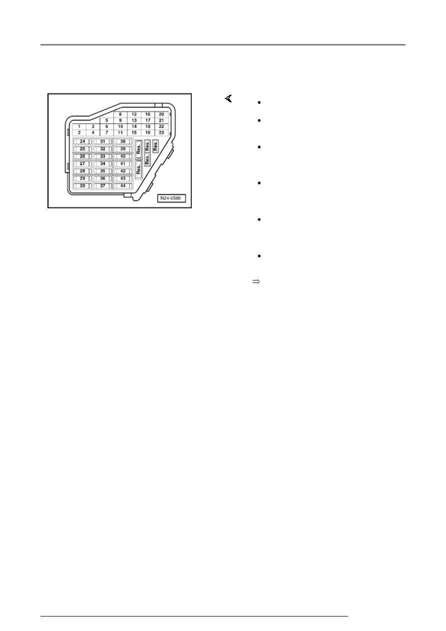
Test requirements
Electrical Wiring Diagrams,
Troubleshooting & Component
Locations
The fuses must be OK.
The battery voltage must be at
least 11.5 V.
All electrical accessories, e.g.
lights and rear window defroster
must be switched off.
If the vehicle is equipped with air
conditioning, this must be
switched off.
Selector lever must be in
position "P" or "N" on vehicles
with an automatic transmission.
Fuel Pump (FP) relay -J17- must
be OK., checking:
Components, checking