содержание .. 626 627 628 629 ..
Toyota Sequoia (2005). Manual - part 628
DIDKP–01
I15876
I21
I20
I19
I22
–
DIAGNOSTICS
AIR CONDITIONING SYSTEM
DI–2307
2501
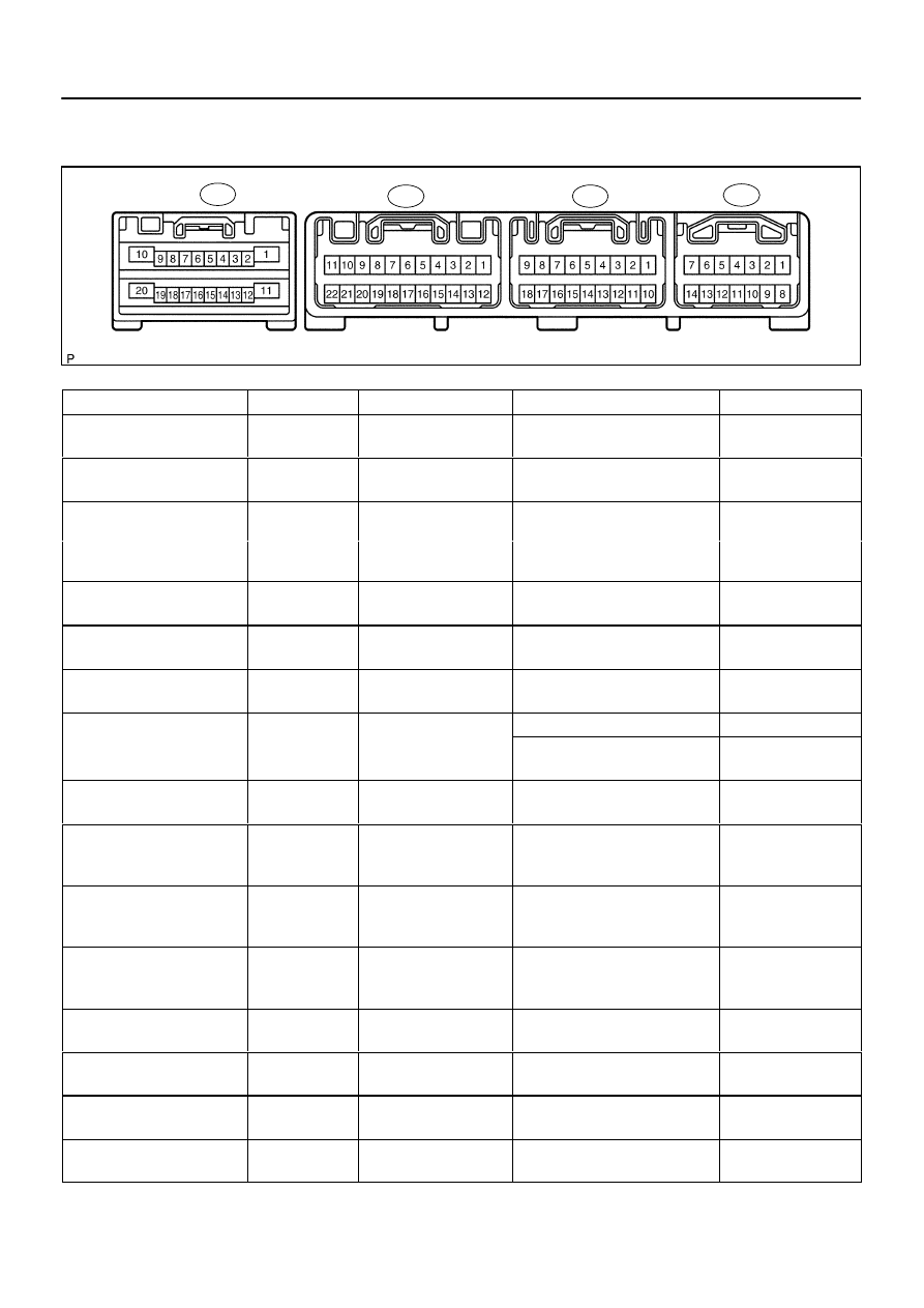
TERMINALS OF ECU
Integration Control and Panel
Symbols (Terminals No.)
Wiring Color
Terminal Description
Condition
Specified Condition
+B
↔
GND
(I19–1
↔
I19–10)
R
↔
O
Power source (Back–up)
Always
10 to 14 V
IG+
↔
GND
(I19–2
↔
I19–10)
R–L
↔
O
Power source (IG)
IG switch OFF
→
ON
10 to 14 V
PSW
↔
GND
L B
O
P
it h i
l
A/C refrigerant pressure: less than
0.19 MPa (2.0 kgf/cm
2
)
10 t 14
B l
1 0 V
PSW
↔
GND
(I19–6
↔
I19–10)
L–B
↔
O
Pressure switch signal
0.19 MPa (2.0 kgf/cm )
or more than 3.14 MPa (32
Kgf/cm
2
)
10 to 14
→
Below 1.0 V
HR
↔
GND
(I22–6
↔
I19–10)
L–Y
↔
O
Blower motor operation
signal
Blower fan OFF
→
ON
10 to 14
→
Below 1.0 V
GND
↔
Body ground
(I19–10
↔
Body ground)
*1
O
↔
Body ground
Ground for main power
supply
Constant
Continuity
ACC
↔
GND
(I19–11
↔
I19–10)
P
↔
O
Power source (ACC)
Turn ignition switch ACC
10 to 14 V
TAM
SG TAM
A bi
t t
t
IG ON, Ambient temp.: 25
°
C (77
°
F)
1.3 to 1.8 V
TAM
↔
SG–TAM
(I19–8
↔
I19–20)
LG–B
↔
Y–B
Ambient temperature sen-
sor signal
IG ON, Ambient temp.: 40
°
C
(104
°
F)
0.8 to 1.3 V
BLW
↔
GND
G B
O
Blower motor operation
Bl
f
OFF
ON
10 t 14
B l
1 0 V
BLW
↔
GND
(I19–4
↔
I19–10)
G–B
↔
O
Blower motor o eration
signal
Blower fan OFF
→
ON
10 to 14
→
Below 1.0 V
RrCLK (I21–15)
*1
B
Communication signal
Communication circuit
(Built in Fr A/C control panel
→
Rr
A/C control panel)
–
RrDPD (I21–5)
*1
R
Communication signal
Communication circuit
(Built in Fr A/C control panel
→
Rr
A/C control panel)
–
RrSWD (I21–6)
*1
W
Communication signal
Communication circuit
(Built in Fr A/C control panel
→
Rr
A/C control panel)
–
RrAMH
↔
GND
(I21–8
↔
I19–10)
*1
R–G
↔
O
Rear air mix control ser-
vomotor operation signal
Rr temp. control switch: Max.
COOL
→
Max. HOT
Below 1.0
→
10 to 14 V for 16 sec.
RrAMC
↔
GND
(I21–9
↔
I19–10)
*1
L–B
↔
O
Rear air mix control ser-
vomotor operation signal
Rr temp. control switch: Max. HOT
→
Max. COOL
Below 1.0
→
10 to 14 V for 16 sec.
RrSG
↔
GND
(I21–10
↔
I19–10)
*1
L–R
↔
O
Ground for rear evapora-
tor temperature sensor
Constant
Continuity
RrS5
↔
RrSG
(I22–4
↔
I21–10)
*1
L–Y
↔
L–R
Power supply for rear air
mix control servomotor
IG ON
4.5 to 5.5 V