содержание .. 547 548 549 550 ..
Toyota Sequoia (2005). Manual - part 549
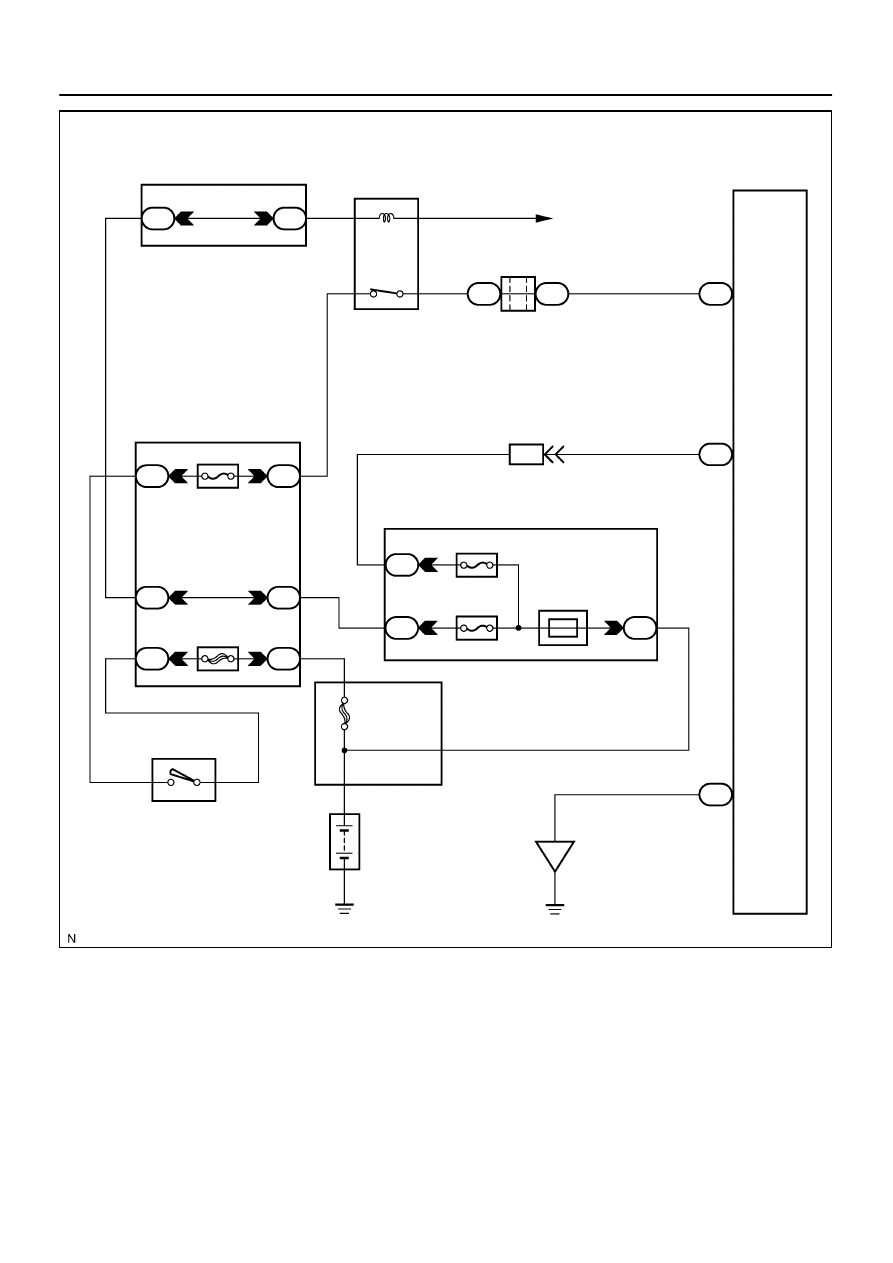
I28498
11
Radio Receiver Assy
ACC+B
1
R4
20
GND
GR
1
RAD No. 2
4
3
A36
ACC Cut Relay
P
3
1
AM1
ACC
12
Sub J/B No. 3
3A
W–R
W–R
1
IA1
24
L–Y
L–Y
2B
3
2C
8
2D
1
Engine Room J/B
RAD No. 1
ECU–B
Short Pin
1J
3
1E
W–R
1L
1
1C
6
AM1
2
ALT
5
B
Battery
IO
BR
Separate Type Amplifier:
R4
R4
3A
I18
Ignition SW
W–L
B
2
12
1
1C
1F
GR
GR
B
C
B–O
J37
To ECM
J38
Instrument Panel J/B
1
2
BU+B
W
8
4
F10
Fusible Link Block
J/C
–
DIAGNOSTICS
AUDIO SYSTEM
DI–1991
2185