Toyota Sequoia (2005). Manual - part 414


  Главная      Automobile - Toyota     Toyota Sequoia - Repair manual 2005 year


поиск по сайту           правообладателям


содержание   ..  412  413  414  415   ..


Toyota Sequoia (2005). Manual - part 414


H01019

H16275

H23590

Airbag 
Sensor 
Assembly

ICL+

ICL–

Floor Wire No. 2

A

B

C

D

Curtain Shield 
Airbag LH Squib

C11

H01019

H16275

H23590

Airbag 
Sensor 
Assembly

ICL+

ICL–

Floor Wire No. 2

A

B

C

D

Curtain Shield 
Airbag LH Squib

C11

DIAGNOSTICS

SUPPLEMENTAL RESTRAINT SYSTEM

DI–1451

1645

4

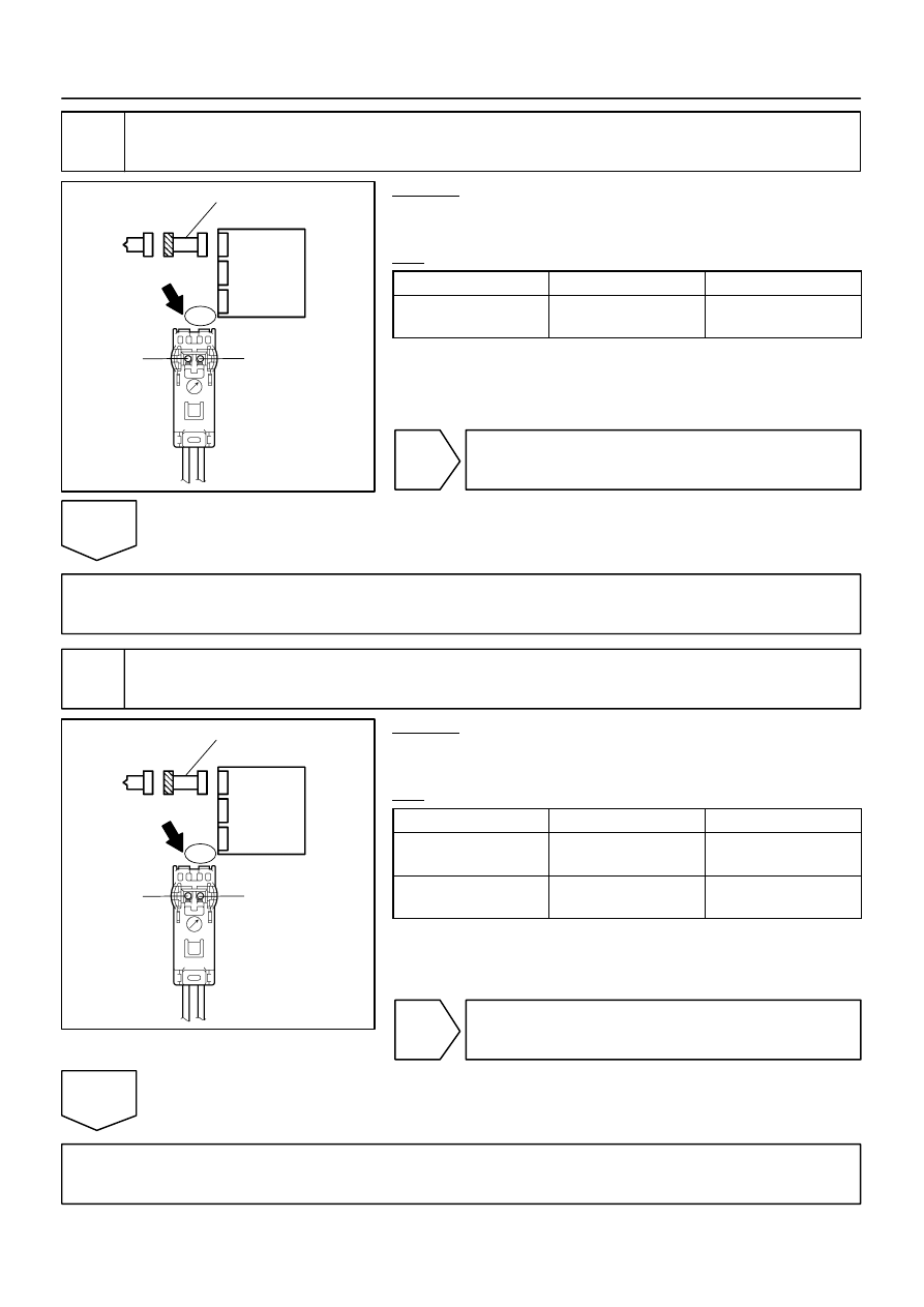
Check floor wire No. 2 (open).

CHECK:
Measure the resistance according to the value(s) in the table
below.
OK:

Tester Connection

Condition

Specified Condition

C11–1 (ICL+) – 

C11–2 (ICL–)

Always

Below 1 

NG

Repair or replace floor wire No. 2.

OK

Go to step 11.

5

Check floor wire No. 2 (short to ground).

CHECK:
Measure the resistance according to the value(s) in the table
below.
OK:

Tester Connection

Condition

Specified Condition

C11–1 (ICL+) – 

Body ground

Always

1 M

 or higher

C11–2 (ICL–) – 

Body ground

Always

1 M

 or higher

NG

Repair or replace floor wire No. 2.

OK

Go to step 11.

H01019

H16275

H23590

Airbag 
Sensor 
Assembly

ICL+

ICL–

Floor Wire No. 2

A

B

C

D

Curtain Shield 
Airbag LH Squib

C11

DI–1452

DIAGNOSTICS

SUPPLEMENTAL RESTRAINT SYSTEM

1646

6

Check floor wire No. 2 (short to B+).

PREPARATION:
Connect the negative (–) terminal cable to the battery, and wait
for at least 2 seconds.
CHECK:
(a)

Turn the ignition switch to the ON position.

(b)

Measure the voltage according to the value(s) in the table
below.

OK:

Tester Connection

Condition

Specified Condition

C11–1 (ICL+) – 

Body ground

Ignition switch ON

Below 1 V

C11–2 (ICL–) – 

Body ground

Ignition switch ON

Below 1 V

NG

Repair or replace floor wire No. 2.

OK

Go to step 11.

7

Check connector.

CHECK:
Check that the floor wire No. 2 connector (on the curtain shield airbag assembly LH side) is not damaged.
OK:

The lock button is not disengaged, or the claw of the lock is not deformed or damaged.

NG

Repair or replace floor wire No. 2.

OK

H01019

H16275

H23590

Airbag 
Sensor 
Assembly

ICL+

ICL–

Floor Wire No. 2

A

B

C

D

Curtain Shield 
Airbag LH Squib

C11

DIAGNOSTICS

SUPPLEMENTAL RESTRAINT SYSTEM

DI–1453

1647

8

Check floor wire No. 2 (curtain shield airbag LH squib circuit).

PREPARATION:
Connect the negative (–) terminal cable to the battery, and wait
for at least 2 seconds.
CHECK:
(a)

Turn the ignition switch to the ON position.

(b)

Measure the voltage according to the value(s) in the table
below.

OK:

Tester Connection

Condition

Specified Condition

C11–1 (ICL+) – 

Body ground

Ignition switch ON

Below 1 V

C11–2 (ICL–) – 

Body ground

Ignition switch ON

Below 1 V

PREPARATION:
(a)

Turn the ignition switch to the LOCK position.

(b)

Disconnect the negative (–) terminal cable from the bat-
tery, and wait for at least for 90 seconds.

CHECK:
Measure the resistance according to the value(s) in the table
below.
OK:

Tester Connection

Condition

Specified Condition

C11–1 (ICL+) – 

C11–2 (ICL–)

Always

Below 1 

C11–1 (ICL+) – 

Body ground

Always

1 M

 or higher

C11–2 (ICL–) – 

Body ground

Always

1 M

 or higher

PREPARATION:
Release the activation prevention mechanism built into the con-
nector ”B” (see page 

DI–1137

).

CHECK:
Measure the resistance according to the value(s) in the table
below.
OK:

Tester Connection

Condition

Specified Condition

C11–1 (ICL+) – 

C11–2 (ICL–)

Always

1 M

 or higher

NG

Repair or replace floor wire No. 2.

OK

H01018

H10600 H16841

H24654

DTC 58

DLC3

TC

CG

Curtain Shield 
Airbag LH Squib

DC

Airbag
Sensor
Assembly

DI–1454

DIAGNOSTICS

SUPPLEMENTAL RESTRAINT SYSTEM

1648

9

Replace curtain shield airbag assembly LH (curtain shield airbag LH squib).

PREPARATION:
(a)

Replace the curtain shield airbag assembly LH (see page

RS–71

).

HINT:
Perform the inspection using parts from a normal vehicle if pos-
sible.
(b)

Connect the connectors to the airbag sensor assembly.

(c)

Connect the negative (–) terminal cable to the battery,
and wait for at least 2 seconds.

CHECK:
(a)

Turn the ignition switch to the ON position, and wait for at
least 60 seconds.

(b)

Clear the DTCs stored in memory (see page 

DI–1147

).

(c)

Turn the ignition switch to the LOCK position.

(d)

Turn the ignition switch to the ON position, and wait for at
least 60 seconds.

(e)

Check the DTCs (see page 

DI–1147

).

OK:

DTC 58 is not output.

HINT:
Codes other than DTC 58 may be output at this time, but they
are not related to this check.

NG

Replace airbag sensor assembly
(see page 

RS–82

).

OK

END


содержание   ..  412  413  414  415   ..